Nadia Yalaoui![]() | Habib Trouzine*
| Habib Trouzine*![]() | Mourad Meghachou
| Mourad Meghachou![]() | Tiago Miranda
| Tiago Miranda![]()
© 2023 IIETA. This article is published by IIETA and is licensed under the CC BY 4.0 license (http://creativecommons.org/licenses/by/4.0/).
OPEN ACCESS
This paper aims to evaluate the impact of geotextile used on strip footing settlement and bearing capacity in sandy soil. Comparing reinforced and unreinforced soil foundations required numerical analysis. To determine their influence on the footing bearing capacity, the stiffness, number, and spacing of reinforcing layers were investigated parametrically using the validated numerical model. The failure stage in the sand was simulated using the Mohr-Coulomb criterion and a non-associated flow rule. The results showed that the geotextile could improve the footing’s bearing capacity and reduce settlement. Finally, a comparison between the previously published experimental findings and the numerical results of this study showed good agreement.
bearing capacity, geotextile, numerical model, reinforced sand
Sandy soils are natural or artificial granular mineral materials used for various civil engineering applications, including backfills behind retaining walls, embankment materials, and foundation soils. They are selected, placed, and compacted to an appropriate specification to achieve the required engineering performance [1]. Algeria is one the countries whose territory constitutes a large part of the Sahara, as this desert stretches on 80% of the country's area where problems relating to construction are encountered [2, 3]. In recent decades, reinforced soil has been widely exploited in geotechnical engineering applications thanks to its economy, ease of construction, and performance. It is utilized in the construction of roads, railway embankments, retaining walls, stabilization of slopes, and in the improvement of soft ground. In these applications, soil engineering characteristics are enhanced through the reinforcement of the soil. The design of a shallow footing involves evaluating its serviceability, performance, and bearing capacity. The former is greatly dependent on the compressibility/deformability of the soils, whereas the latter depends on the soil strength characteristics. In particular, an approach is suggested to calculate the increase in the bearing capacity due to one or more layers of geotextile reinforcement placed within the foundation soil. This study examines the effect of the performance of different reinforcement parameters optimal for improving the bearing capacity of the strip footings supported by the sand bed with and without geotextile. For this purpose, a numerical simulation of finite elements has been done to determine the influence of the spacing of the first layer of reinforcement (u), the spacing between the layers (h), and the number of layers of geotextile (N), as well as the rigidity of reinforcement, for better bearing capacity. The results are then compared with those of prior studies [4-10].
The failure mechanism of on reinforced soil - based footings is known not to be a simple issue, considering the limited knowledge relating to their load settlement behavior. Many experimental, numerical, and analytical studies have investigated the behavior of reinforced soil foundations for different soil types [11-17]; all these studies demonstrated that the bearing capacity of shallow foundations increases when the foundation is reinforced. The first researchers to examine the impact of soil reinforcement on the increase of the bearing capacity of shallow foundations were Binquet and Lee [4, 18]. Many researchers used the bearing capacity ratio to assess reinforced soil foundations' advantages (BCR). Many of these studies investigated the factors and elements influencing the BCR value. Yetimoglu et al. [6] conducted physical and numerical modeling of a rectangular footing resting on top of geogrid-reinforced sand. They performed small-scale model footing tests and a finite element analysis (FEA). Their results indicated that the highest BCR was achieved when the single-layer reinforcement was placed at 0.3B (where B is footing depth). The top layer of multi-layer reinforcement should be 0.25B, and the optimum vertical spacing of reinforcement layers should vary between 0.2B and 0.4B. They reported that the more reinforced layers there were, the more there BCR increased. Maharaj [19] investigated the influence of top layer depth, the vertical spacing of reinforcement layers, the reinforcement length, and the number of layers on the settlement of strip footing on reinforced clay using 2D non-linear FEA. The optimum layer depth for single-layer reinforcement was around 0.125B, and the effective reinforcement length ratio (l/B) was around 2.0. The influence depth was determined by the stiffness of the reinforcement, and increasing the stiffness of the geosynthetics resulted in less footing settlement. El Sawwaf [20] suggested that the depth and spacing of reinforcing geogrid should be 0.6B and 0.5B, respectively. In addition, they recommended using three layers and that the geogrid length should be greater than or equal to five times the footing width. Ahmed et al. [21] investigated how well embankment building performed over weak subgrade soil using FEA. They adopted a modified cam-clay model for clay soil and a non-linear elastic-plastic model for sand, while a linear elastic model was used to represent geosynthetic materials. They reported that geogrid performed much better than geotextile. The best performance was achieved when geosynthetic reinforcements were nearest the footing. The strain within geosynthetics becomes negligible at a distance of 6B. They also noted that introducing geosynthetics resulted in better stress distribution and deformation patterns within the embankment. Similarly, Latha and Somwanshi [22] performed FEA of square footings resting on sand using an elastic–perfectly plastic Mohr-Coulomb model to simulate the behavior of sand. They reported that the optimum spacing of reinforcing layers within the effective reinforcement zone was 0.4B, and the optimum reinforcement length, l was 4B. The impacts of utilizing nonwoven geotextile to increase the ultimate bearing capacity of footings sitting on medium-density sand are studied by Tavangar and Shooshpasha [23]. The testing findings demonstrated the system's maximum bearing capacity with four geotextile layers, a vertical layer separation of 0.3 B, and a geotextile width of 4 B. Moreover, by doing 3-D finite element studies with various sizes of the square plate, the influence of plate size and the sample size was quantitatively investigated. The numerical investigations showed that the bearing capacity ratio (BCR) values gradually decrease when the plate size increases to 65 cm. A further increase in plate size has little impact on BCR values. According to Sridhar and Prathapkumar [24], the number of layers of geotextile affects the bearing capacity of coir geotextile-reinforced sand. Peak stress, bearing capacity ratio, and settling reduction factor was used as comparison variables for various d/B ratios. Theoretical values validated the experimental values of bearing capacity. It can be claimed that N=3 to N=4 layers correspond to the ideal number of layers in terms of bearing capacity and settlement reduction factor (SRF). For N=4, The BCR is a maximum. The results of laboratory model testing on square footings lying on nonwoven geotextile-reinforced sand were presented by Tavangar and Shooshpasha [25]. Their results comprehensively demonstrated that nonwoven geotextiles increase the bearing capacity of footings in all cases. The findings also imply that as the relative density rises, the bearing capacity ratio also steadily rises. The optimum placement depth is between 0.3 and 0.4B. Thamer and Shaia [26] suggested that soil reinforced with geotextiles could help increase the soil's bearing capacity. According to the results, the system that achieves the greatest bearing capacity has three geotextile layers, 0.25B vertical spacing, and a geotextile width of 5B. The results also showed that the reinforced silty sand's behavior significantly impacted the reinforcement design. Jaiswal and Chauhan [27] noted that the optimum depth of the first layer of reinforcement having wraparound ends is 0.3 times the width of the footing, and further, an increase in depth of the placement of the reinforcing layer does not affect the BCR. The number of reinforcing layers with a specific geometric arrangement also helps improve the ultimate load-bearing capacity. According to their findings, the optimum depth of the first layer of reinforcement from the bottom of the footing and the width of the reinforcing layers are 0.3 and 1.5 times the width of the footing, respectively, and the optimum number of reinforcement layers was three. However, adding more reinforcement does not change the footing's bearing capacity ratio beyond three layers.
The present study used the finite-element method to investigate the behavior of a strip footing resting on unreinforced and reinforced sand. The geometry of a typical finite element model used for the analysis is shown in Figure 1. Plaxis 2D was used for this study. The modeled foundation was a strip foundation of width B=1 m, supported on sandy soil and solicited by a maximum central vertical load of P=400 kN/m. The foundation sand soil is reinforced by N (number) geotextile layers; h and u are the spacing between the layers and the depth between the top layer and the bottom of the footing. The reinforcement is spaced over 4 m below the footing. The soil medium is simulated using 15-node triangular plane strain elements. The soil behavior was represented utilizing the elastic–perfectly plastic Mohr-Coulomb model, which requires five parameters: Young modulus E, Poisson's ratio υ, cohesion C, internal friction angle φ, and a dilatancy angle ψ. In this study the same boundary conditions as the Khedkar and Mandal [28] models are used. The bottom boundary is prevented from moving in both directions.
Figure 1. Geometry of the reinforced soil
In contrast, the vertical boundary is fixed horizontally, so the sand cannot move horizontally beyond the limit, yet the settlement of sand is permitted. Two types of geotextiles were considered, namely: Mirafi HP 570 (GEO1) and Tensar Basetex 400/50 (GEO2) (woven geotextile). A 5-node tension element was used to simulate the geotextile reinforcement without pre-stress. The elastic axial stiffness EA was the sole material characteristic needed for the geotextile. The interaction between soil and geosynthetics is of utmost importance in geosynthetic-reinforced soil structure design and stability analysis. Factors such as the geometry of a reinforced soil system and its construction process may affect soil–geosynthetic interaction properties. In addition, the interaction properties are strongly determined by the mobilized interaction mechanism, the physical and mechanical properties of the soil, and the mechanical and geometrical properties of the reinforcement [29]. In the present analysis, the interface element is assigned a virtual thickness to define the interface's material properties. The interface's material properties are related to the adjacent soil material by a strength reduction factor (Rinter). The interface element's virtual thickness is small and is calculated as the virtual thickness factor times the average element size. This study used the Mohr-Coulomb material model to model stress-strain behavior. The strength reduction coefficient (Rinter) is defined as:
$\mathrm{R}_{\text {inter }}=\frac{\mathrm{C}_{\text {inter }}}{\mathrm{C}_{\text {soil }}}=\frac{\tan \varphi_{\text {inter }}}{\tan \varphi_{\text {soil }}}$ (1)
where, Csoil and $\varphi_{\text {soil }}$ are the cohesion and friction angles of the soil adjacent to the interface, Cinter and $\varphi_{\text {inter }}$ are the adhesion and friction angles of the interface [30]. Thus, an elastic-plastic model is used to describe the behavior of interfaces.
The interface between soil and geotextile was defined as the fully-bonded interface (Rinter=1), as the occurrence of full friction caused by the texture of the geotextile and relative movement was not observed between the soil and geotextile [31]. Accordingly, the friction angle at the sand-reinforcement interface is assumed to equal the sand's friction angle in the adjacent zone. No slippage between sand and reinforcement and no pullout failure of reinforcement was observed in the physical experimental test results conducted by Kotake et al. [32].
The strip footing is simulated by creating a rectangular region and using a linear elastic material model. The model parameters used in the numerical simulation are tabulated in Table 1. Different configurations considered in this study are presented in Table 2.
Table 1. Properties of the soil used in the numerical simulations
|
Parameters |
Sand |
Footing (concrete) |
GEO1 (geotextile) |
GEO2 (geotextile) |
|
Unit weight: kN/m3 |
17 |
25 |
- |
- |
|
Young modulus: kN/m2 |
13000 |
3x10⁵ |
- |
- |
|
Poisson’s ratio |
0.28 |
0.2 |
- |
- |
|
Friction angle |
31° |
- |
- |
- |
|
Dilatancy angle |
0° |
- |
- |
- |
|
Cohesion: kN/m2 |
0.1 |
- |
- |
- |
|
Interface reduction factor (Rinter) |
1 |
1 |
- |
- |
|
EA: kN/m |
- |
- |
700 |
5365 |
Table 2. Details of model test program
|
Constant Parameters |
Variable Parameters |
|
Unreinforced sand |
N=0 |
|
b=4B; u/B =0. 3; h/B=0.3 |
Geotextile type (GEO1, GEO2) N=3; 4 |
|
b=4B; u/B=0.3; h/B=0.3; GEO2 |
N=1; 2; 3; 4 |
|
b=4B; N=1; GEO2 |
u/B=0.1 to 0.8 |
|
b=4B; u/B=0.3; GEO2 |
h/B=0.2 to 1 N=2; 3; 4 |
The bearing capacity ratio BCR evaluates the improvement in bearing capacity due to the provision of geotextile reinforcement. According to Binquet and Lee [18], BCR is defined as follows:
$\mathrm{BCR}=\frac{\mathrm{q}_{\mathrm{r}}}{\mathrm{q}_0}$ (2)
where, qr is the bearing pressure of the reinforced soil at a given settlement, and q0 is the bearing pressure of unreinforced soil at the same settlement.
4.1 The influence of type of reinforcement
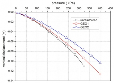
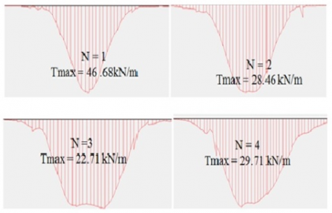
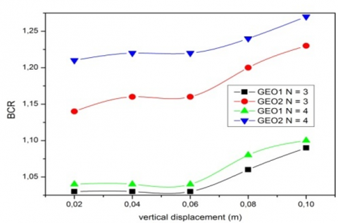
Two different types of reinforcement are considered in this study, and their properties are presented in Table 2. Geotextile GEO1 and GEO2 are arranged in 4 layers spaced at 0.3B. Figure 2 (a) displays the load-displacement curves at point A under the foundation axis. This point exhibits the maximum settlement for a given elevation. The improvement of reinforced soil behavior (i.e., reduced settlement under applied load) is correlated to the increase of geotextile elastic modulus. The decrease in the settlement, which is associated with an increase in foundation-bearing capacity, is attributed to the friction between the geotextile material and soil that mobilizes shearing resistance resulting in additional soil confinement and consequently limiting settlement. As it is possible to state in Figure 2 (b), the tensile force is maximum within the central third of reinforcement due to the additional confinement of the footing load, gradually decreasing towards the edge of reinforcement. Kurian et al. [33] made a similar observation. Figure 3 shows the BCR based on settlement consideration for the two types of geotextile reinforcement. The results show that GEO2 geotextile significantly increased BCR, especially when using four reinforcement layers. For example, the relative gain in BCR employing GEO2 over GEO1 is 12% and 15% for N=3 and 4.
(a)
(b)
Figure 2. (a) Pressure-displacement curves at point A with different types of reinforcement; (b) The tensile force at the geotextile layers
(a)
(b)
Figure 3. Improvement factor variation with displacement (variable EA)
Figure 3 (b) illustrates the variation of BCR according to vertical displacement and the number of reinforcement layers. The soil-bearing capacity increases with a high number of layers. For example, BCR respectively increases from 1.04 to 1.22, for N=1 to N=4 and for displacement of 0.06m.
4.2 Effect of number of layers on BCR and settlement
The granular medium is reinforced with layers of GEO2 spaced about 0.3B between them with an axial rigidity equal to 5437kN/m. Pressure-displacement curves for a different number of geotextile layers (N), varying from 1 to 4, are shown in Figure 4 (a). The behavior of the footing placed on unreinforced sand is included in the figure for comparison. The figure shows that soil reinforcement significantly increases initial stiffness and bearing load at the same settlement level. Additionally, the number of geotextile layers significantly reduces settlement for a given footing load. The curves demonstrate that the addition of four geotextile layers increased the bearing load to 400kN/m2 compared to 305kN/m2 for unreinforced sand, which is a number that represents an almost 30% increase. The reinforcing mechanism, which limits sand particles' spreading and lateral deformations, is responsible for this increase in ultimate load. The geotextile resists withstanding the imposed horizontal shear stresses created in the soil mass under the loaded area because of the mobilized tension in the reinforcement. The contact area and the interface between the geotextile layers and the soil increase with the number of geotextile layers. Consequently, large soil displacements and horizontal shear stresses built up in the soil under the footing were reduced and transferred by geotextile layers to a more extensive soil mass [34, 35].
(a)
(b)
Figure 4. (a) Pressure-displacement curves at point A with a different number of geotextile layers; (b) Improvement factor variation with displacement (N variable)
Figure 5. The vertical displacement with a number of layers
Apart from the economic aspect that would limit an excessive number of layers, previous work has shown that, on the whole, the use of a reinforcement system with more than four layers improves the bearing pressure only to a negligible extent and that in some other cases, on the contrary, BCR diminution is noticed. It might be related to the inter-lateral slip of soil and the different reinforcement layers [5, 6, 11]. The graphical representation of Figure 5 for the various cases cited above clearly shows the total relative reduction of settlement below the foundation with the increasing number of reinforcing layers compared to the unreinforced configuration.
4.3 Depth effect of the first layer
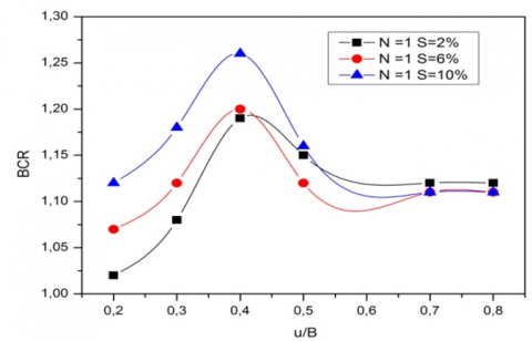
The search for the best positioning of the layers beneath the foundation has motivated this study. To do this, a single layer is treated (N=1) with the change in the depth ratio u/B: 0.1; 0.2; 0.3; 0.4; 0.8. Figure 6 (a) shows the load-displacement curves for reinforced sand compared to the unreinforced medium.
Figure 6 (b) shows that the BCR has an optimum value for u=0.4B. This optimal value is included in the area proposed by Chen [9]. On both sides, the BCR decreases abruptly. Therefore, when using a single reinforcement layer, it is recommended to place it at a distance that corresponds to this optimum. When the distance (u) between the first layer and the base of the foundation is less than 0.25B, the gain in bearing capacity is probably low due to the tensile failure of the geotextile, according to the research [4].
(a)
(b)
Figure 6. (a) Pressure-displacement curves with the depth of the first reinforcement layer; (b) BCR versus u /B for one layer of reinforcement
The bearing capacity is reduced if the distance (u) exceeds the optimum value. The layer moves away from the area influence of a load of footing and cannot even respond to requests for important values of (u). It should be noted that, usually, when this distance is more significant than 0.6B, the soil's shear failure can occur under the foundation of the work of Binquet and Lee [4]. When (u) varies between 0.25B and 0.4B, the reinforcing layers are solicited positively; that is to say, they mobilize more and more shear strength, and the interaction soil-geotextile then plays its full role at the optimum u=0,4B.
4.4 Effect of vertical spacing of reinforcement layers
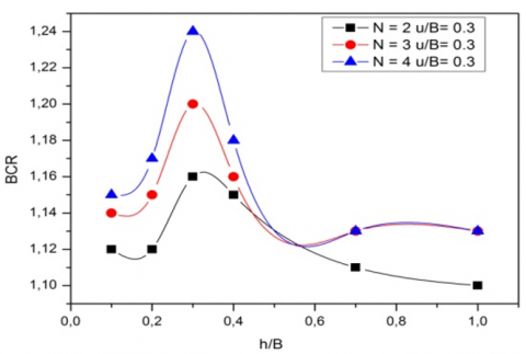
In this study the vertical spacing between the layers GEO2 (h) were varied between 0.2B; 0.3B; 0.4B; 0.5B; 0,7B; 1B. The study was performed for a different number of reinforcement layers (N): 2, 3, and 4. Figure 7(a) show the evolution of settlements based on the loading for four layers. The bearing capacity of unreinforced soil is around 320 kPa for a settlement of about 11 cm. The bearing capacity is improved by introducing geotextile layers for the same settlement. However, the gain in soil strength is insignificant for large spacing between the layers, with h values beyond h=0.7B. The optimal spacing, giving the most important improvement bearing capacity factor, is obtained when the geotextile layers are spaced at 0.3B. These results are similar to those obtained by other researchers [6, 9].
Figure 7(b) shows that the optimum h=0.3B remains unchanged when the number of layer changes N increases from 2 to 4. The BCR factor is great for N=4 to N=2, with respective values of BCR being 1.24 and 1.16. As the spacing h between the reinforcement layers increases, the soil-geotextile interaction decreases, mobilizing a lesser frictional force developed at the soil-reinforcement interface. When this spacing becomes important, the reinforced soil tends to lose soil reinforcement interaction and behaves like unreinforced soil, where shear failure can be generated. Finally, the optimum spacing gives the device a layer-soil tangle mobilizing an optimal reinforcement confinement system.
(a)
(b)
Figure 7. (a) Pressure-displacement curves with a spacing of geotextile layers (N=4); (b) BCR versus h/B with a number of layers
The numerical results of reinforced strip footing obtained from PLAXIS 2D were validated with the results obtained from the experimental by Binquet et al. [4], Das et al. [7], and Patra et al. [8]. The purpose of this study was to validate the finite-element model of unreinforced and geotextile-reinforced foundation sections done in PLAXIS. Table 3 shows a comparison of the optimum parameters conducted to find out the best location and configuration of the geotextile layers such that the depth of the first reinforcement (u), the vertical spacing between layers (h), and the width of the reinforcement (b), that gives the optimum improvement in bearing capacity and reduced settlement. The predicted values by using the numerical solution of this study are in good agreement with the test results of Binquet et al. in researches [4, 18], Das et al. [7], and Patra et al [8] for u/B and h/B. On the other hand, b/B is less than in researches [7, 8].
Table 3. Result previous research of optimum parameters
|
|
[18] |
[5] |
[6] |
[7] |
[8] |
[9] |
[10] |
Present study |
|
Footing shape |
strip |
square |
Rectangular |
strip |
strip |
rectangular |
square |
strip |
|
Reinforcement type |
Aluminum |
Geotextile |
Geogrid |
Geogrid |
Geogrid |
Geogrid |
Geogrid |
Geotextile |
|
(u/B)opt |
0.3 |
- |
0.25 – 0.3 |
0.3 |
0.35 |
0.33 |
- |
0.3 |
|
(h/B)opt |
- |
- |
0.2 – 0.4 |
- |
0.25 |
0.33 |
0.4 |
0.3 |
|
(b/B)opt |
- |
3 |
4.5 |
8 |
5 |
5 |
4 |
4 |
(1) To estimate the bearing capacity of a strip footing built on the surface sand reinforced with geotextile, numerical computations based on Plaxis were carried out. The numerical analysis revealed the effects of some parameters on the bearing capacity of the footing using the tensile stiffness, the number of reinforcements, the depth of the first reinforcing layer, and the vertical distance between reinforced layers. Their effects on the bearing capacity are evaluated and compared with the results obtained from other experimental research. Based on the analyses performed in this study, the study's conclusion can be summarized as follows: 1. In general, using geotextile reinforces the behavior of granular soils, increases the bearing capacity, and reduces settlement under the foundation; this is true for whatever rigidity values of the geotextile layers; they are due to the shear stress mobilized between the soil and the geotextile layers, which confers a horizontal tensile strength and minimizes vertical displacement.
(2) The bearing capacity increases with increasing rigidity and the number of reinforcement layers. The BCR factor decreases with increasing the vertical spacing between the reinforcement layers.
(3) The optimum spacing between the first reinforcing layer and the base of the foundation equals u/B=0.4 in the case of a single layer of geotextile.
(4) The optimum spacing between layers of geotextile (h) is estimated to be approximately one-third of the footing width (h/B=0.3). Also, the optimal spacing of the reinforcement system requires the provision of the first layer at a distance of u=0.3B.
(5) A hydromechanical coupled simulation of these system should be studied in further details.
|
B |
Width of the footing (m) |
|
b |
Length of geotextile reinforcement (m) |
|
BCR |
Bearing capacity ratio (dimensionless) |
|
h |
Vertical spacing between reinforcement (m) |
|
N |
Number of geotextile layers (dimensionless) |
|
Rinter |
Interface reduction factor (dimensionless) |
|
Tmax |
The tensile force at the geotextile layers (kN/m) |
|
u |
Top layer spacing of geotextile from the bottom of the footing (m) |
[1] Kazi, M., Shukla, S.K., Habibi, D. (2015). Effect of submergence on settlement and bearing capacity of surface strip footing on geotextile-reinforced sand bed. International Journal of Geosynthetics and Ground Engineering, 1: 1-11. https://doi.org/10.1007/s40891-014-0006-y
[2] Mahmoudi, H., Spahis, N., Goosen, M.F., Sablani, S., Abdul-wahab, S.A., Ghaffour, N., Drouiche, N. (2009). Assessment of wind energy to power solar brackish water greenhouse desalination units: A case study from Algeria. Renewable and Sustainable Energy Reviews, 13(8): 2149-2155. https://doi.org/10.1016/j.rser.2009.03.001
[3] Bouzidi, B. (2011). Viability of solar or wind for water pumping systems in the Algerian Sahara regions–case study Adrar. Renewable and Sustainable Energy Reviews, 15(9): 4436-4442. https://doi.org/10.1016/j.rser.2011.07.108
[4] Binquet, J., Lee, K.L. (1975). Bearing capacity analysis of reinforced earth slabs. Journal of the Geotechnical Engineering Division, 101(12): 1257-1276. https://doi.org/10.1061/AJGEB6.0000220
[5] Guido, V.A., Chang, D.K., Sweeney, M.A. (1986). Comparison of geogrid and geotextile reinforced earth slabs. Canadian Geotechnical Journal, 23(4): 435-440. https://doi.org/10.1139/t86-073
[6] Yetimoglu, T., Wu, J.T., Saglamer, A. (1994). Bearing capacity of rectangular footings on geogrid-reinforced sand. Journal of Geotechnical Engineering, 120(12): 2083-2099. https://doi.org/10.1061/(ASCE)07339410(1994)120:12(2083)
[7] Das, B.M., Shin, E.C., Omar, M.T. (1994). The bearing capacity of surface strip foundations on geogrid-reinforced sand and clay—A comparative study. Geotechnical & Geological Engineering, 12: 1-14. http://dx.doi.org/10.1007/BF00425933
[8] Patra, C.R., Das, B.M., Atalar, C. (2005). Bearing capacity of embedded strip foundation on geogrid-reinforced sand. Geotextiles and Geomembranes, 23(5): 454-462. https://doi.org/10.1016/j.geotexmem.2005.02.001
[9] Chen, Q. (2007). An experimental study on characteristics and behavior of reinforced soil foundation. PhD dissertation, Louisiana State University, Baton Rouge, USA.
[10] Latha, G.M., Somwanshi, A. (2009). Bearing capacity of square footings on geosynthetic reinforced sand. Geotextiles and Geomembranes, 27(4): 281-294. https://doi.org/10.1016/j.geotexmem.2009.02.001
[11] Adams, M.T., Collin, J.G. (1997). Large model spread footing load tests on geosynthetic reinforced soil foundations. Journal of Geotechnical and Geoenvironmental Engineering, 123(1): 66-72. https://doi.org/10.1061/(ASCE)1090-0241(1997)123:1(66)
[12] Kumar, A., Kaur, A. (2012). Model tests of square footing resting on fibre-reinforced sand bed. Geosynthetics International, 19(5): 385-392. http://dx.doi.org/10.1680/gein.12.00024
[13] Javdanian, H., Haddad, A., Mehrzad, B. (2012). Experimental and numerical investigation of the bearing capacity of adjacent footings on reinforced soil. Electronic Journal of Geotechnical Engineering, 17: 2597-2617.
[14] Abu-Farsakh, M., Chen, Q., Sharma, R. (2013). An experimental evaluation of the behavior of footings on geosynthetic-reinforced sand. Soils and Foundations, 53(2): 335-348. https://doi.org/10.1016/j.sandf.2013.01.001
[15] Dixit, M.S., Patil, K.A. (2014). Effect of reinforcement on bearing capacity and settlement of sand. Electronic Journal of Geotechnical Engineering, 19: 1033-1046.
[16] Hegde, A., Sitharam, T.G. (2015). 3-Dimensional numerical modelling of geocell reinforced sand beds. Geotextiles and Geomembranes, 43(2): 171-181. https://doi.org/10.1016/j.geotexmem.2014.11.009
[17] Badakhshan, E., Noorzad, A. (2017). Effect of footing shape and load eccentricity on behavior of geosynthetic reinforced sand bed. Geotextiles and Geomembranes, 45(2): 58-67. http://dx.doi.org/10.1016/j.geotexmem.2016.11.007
[18] Binquet, J., Lee, K.L. (1975). Bearing capacity tests on reinforced earth slabs. Journal of the Geotechnical Engineering Division, 101(12): 1241-1255. https://doi.org/10.1061/AJGEB6.0000219
[19] Maharaj, D.K. (2003). Nonlinear finite element analysis of strip footing on reinforced clay. The Electronic Journal of Geotechnical Engineering, 8: 241-256.
[20] El Sawwaf, M.A. (2007). Behavior of strip footing on geogrid-reinforced sand over a soft clay slope. Geotextiles and Geomembranes, 25(1): 50-60. http://dx.doi.org/10.1016/j.geotexmem.2006.06.001
[21] Ahmed, A., El-Tohami, A.M.K., Marei, N.A. (2008). Two-dimensional finite element analysis of laboratory embankment model. In geotechnical engineering for disaster mitigation and rehabilitation: Proceedings of the 2nd International Conference GEDMAR08, Nanjing, China, pp. 1003-1018. http://dx.doi.org/10.1007/978-3-540-79846-0_133
[22] Latha, G.M., Somwanshi, A. (2009). Effect of reinforcement form on the bearing capacity of square footings on sand. Geotextiles and Geomembranes, 27(6): 409-422. https://doi.org/10.1016/j.geotexmem.2009.03.005
[23] Tavangar, Y., Shooshpasha, I. (2016). Experimental and numerical study of bearing capacity and effect of specimen size on uniform sand with medium density, reinforced with nonwoven geotextile. Arabian Journal for Science and Engineering, 41: 4127-4137. https://doi.org/10.1007/s13369-016-2101-y
[24] Sridhar, R., Prathapkumar, M.T. (2017). Behaviour of model footing resting on sand reinforced with number of layers of coir geotextile. Innovative Infrastructure Solutions, 2(1): 50. https://doi.org/10.1007/s41062-017-0099-y
[25] Tavangar, Y., Shooshpasha, I. (2020). Impacts of a nonwoven geotextile arrangement on load-bearing capacity of reinforced sand: A laboratory study. Innovative Infrastructure Solutions, 5: 1-9. https://doi.org/10.1007/s41062-019-0253-9
[26] Thamer, L., Shaia, H. (2021). The effect of geotextile layers and configuration on soil bearing capacity. Mathematical Modelling of Engineering Problems, 8(6): 897-904. https://doi.org/10.18280/mmep.080608
[27] Jaiswal, S., Chauhan, V.B. (2021). Response of strip footing resting on earth bed reinforced with geotextile with wraparound ends using finite element analysis. Innovative Infrastructure Solutions, 6(2): 121. https://doi.org/10.1007/s41062-021-00486-0
[28] Khedkar, M.S., Mandal, J.N. (2009). Pullout behaviour of cellular reinforcements. Geotextiles and Geomembranes, 27(4): 262-271. https://doi.org/10.1016/j.geotexmem.2008.12.003
[29] Ferreira, F.B., Vieira, C.S., Lopes, M.D.L. (2015). Direct shear behaviour of residual soil–geosynthetic interfaces–influence of soil moisture content, soil density and geosynthetic type. Geosynthetics International, 22(3): 257-272. https://doi.org/10.1680/gein.15.00011
[30] Chia-Cheng, F., Chih-Chung, H. (2010). The mechanical behaviour and design concerns for a hybrid reinforced earth embankment built in limited width adjacent to a slope. Journal Computers and Geotechnics, 38(2): 233-247. https://doi.org/10.1016/j.compgeo.2010.11.012
[31] Şadoğlu, E. (2015). Numerical analysis of centrally and eccentrically loaded strip footing on geotextile-reinforced sand. Geosynthetics International, 22(3): 225-234. https://doi.org/10.1680/gein.15.00007
[32] Kotake, N., Tatsuoka, F., Tanaka, T., Siddiquee, M.S.A., Huang, C.C. (2001). FEM simulation of the bearing capacity of level reinforced sand ground subjected to footing load. Geosynthetics International, 8(6): 501-549. https://doi.org/10.1680/gein.8.0205
[33] Kurian, N.P., Beena, K.S., Kumar, R.K. (1997). Settlement of reinforced sand in foundations. Journal of Geotechnical and Geoenvironmental Engineering, 123(9): 818-827. https://doi.org/10.1061/(ASCE)1090-0241(1997)123:9(818)
[34] El Sawwaf, M., Nazir, A.K. (2012). The effect of deep excavation-induced lateral soil movements on the behavior of strip footing supported on reinforced sand. Journal of Advanced Research, 3(4): 337-344. https://doi.org/10.1016/j.jare.2011.11.001
[35] Sahu, R., Patra, C.R., Sivakugan, N., Das, B.M. (2020). Behavior of inclined loaded strip footings resting on geogrid–reinforced sand. Geotechnical and Geological Engineering, 38: 5245-5256. https://doi.org/10.1007/s10706-020-01360-z