Xuan Ngoc Nguyen*![]() | Thanh Tam Tran
| Thanh Tam Tran![]()
© 2023 IIETA. This article is published by IIETA and is licensed under the CC BY 4.0 license (http://creativecommons.org/licenses/by/4.0/).
OPEN ACCESS
Rollover accidents of passenger vehicle in the process of moving will cause danger to human life and property. Therefore, the driver needs to actively control the speed of the vehicle to avoid dangerous problems. During a steady turn, a vehicle moving at a speed of over 35 km/h will overturn, similar to when a vehicle changes lanes at a speed of over 110 km/h. The above results are evaluated based on the load transfer ratio (LTR) and the difference of the roll angle of the suspended and unsuspended mass. In this study, the author has applied D'Alembert's principle to establish the investigational differential equation system based on the dynamic model of vehicle rollover stability and used Runge-Kutta method in Matlab Simulink to simulate in time domain. The article and determined the vehicle response sensitivity at dangerous steering frequencies in the frequency domain. Research results can provide speed recommendations for drivers during driving.
passenger vehicle, horizontal stability, D'Alembert's principle, load transfer ratio (LTR), changes lane, rollover stability
Currently, passenger vehicle is widely used all over the world. Passenger safety is a top priority in travel. The most dangerous situation that can happen is a car rollover. This affects almost all passengers on board. According to the statistical report [1], the accident rate due to rollover between 2019 and 2020 increased by 9%. Therefore, there are many authors or studies focusing on identifying problems related to vehicle rollover stability in order to minimize the danger to the life and property of passengers. In the study [2], the author uses a dynamic model of the vehicle in the horizontal and vertical planes to simulate changes from the lateral, rolling and yawing, in addition to the basic parameters of the vehicle and road is also included for analysis based on TruckSim, the results show that the vehicle tends to rollover when there is an impact on the wheel and the third axle of the vehicle, the torsional stiffness of the body has an effect on rollover stability of a triaxle bus. Marimuthu et al. [3] have studied on SUV (Sports Utility Vehicle) by building a nonlinear dynamics model in Matlab Simulink with the input signal of Fishhook steering control, based on the factor of SSF (Static Stability Factor), RSF (Roll Stability Factor) and TWLV (Two Wheel Lift off Velocity) determine the height of the vehicle's center of gravity and the basic tire parameters that affect rollover stability characteristic of the vehicle. Similar to the above study, Zhao [4] used a 3-degrees-of-freedom heavy truck dynamics model and used the Lateral Transfer Ratio (LTR) value to evaluate the vehicle's rollover stability, the results of the analysis indicate that the load mass and the position of the center of gravity have the greatest impact on the rollover stability, which can be improved by reducing the height of the load mass, increasing the wheelbase and the track. In the study of Joshi et al. [5] also showed that when changing the steering frequency from 0 to 2 Hz of the input signal and the horizontal acceleration is still kept at steady state 4 m/s2 with the vehicle speed according to ISO 7401:2011 are 80 and 100 km/h affecting the lateral dynamics of SUV vehicle. In the article [6], based on the Routh–Hurwitz criterion, the author has determined the roll stability conditions from the linear model of three degrees of freedom in the case of lane change and turning at high speed, the simulation analysis shows that the longitudinal distance from the center of gravity to the front axle and the steering angle of the front wheels are stable areas and it is related to vehicle speed and vehicle parameters.
In addition, Sun et al. [7] used the state-space equations to analyze the 7 degrees of freedom (DOFs) of the vehicle with the input signal of 90 degrees steering angle, the influencing factors is a structural parameter of the vehicle, analysis of the results shows that to enhance the vehicle's rollover stability by increasing the stiffness of the suspension and tracks, reducing the height of the center of gravity of the sprung mass. In the study [8], the authors also used a 7 DOFs dynamic model to analyze the factors affecting the roll stability of the vehicle, including vehicle speed, load, the height of the vehicle's center of gravity and nonlinear Pacejka tire model combined with Fishhook steering angle, the analysis results show that the tire track, suspension parameters and road excitation affect the vehicle's rollover stability. Some authors also study for Heavy Articulated Vehicles (HAV) as in the study [9], applying the Davies method for a three dimensional trailer dynamics model which to evaluate based on the static rollover threshold (SRT) factor, the author determined the SRT factor can reduce or increase by that the vertical and lateral displacement, and increase with the longitudinal displacement of the car. Besides determining the factors affecting roll stability, the authors [10] also tested on 3-wheel vehicles (TWVs), which are built to save fuel and are cheap, it is necessary to check the stability of the vehicle in the case of a 39 degree tilt test, the test shows that the vehicle is stable when increasing the wheel track and decreasing the seat height. In the research [11], the authors also applied both theory and experiment to test the vehicle rollover warning system through the rollover time warning algorithm (TTR) to analyze the dynamic model of the vehicle with Carsim and Matlab Simulink, simulation results show that dangerous speeds of 50 km/h and 40 km/h correspond to zigzag and stable driving conditions.
Although the dynamics of rollover stability have been studied for a long time in the world, this is still an area of research interest of scientists. However, the above studies have not mentioned the horizontal stabilizer bar on the vehicle. Thus, the author also wants to analyze more clearly about the stability of the passenger vehicle when it is equipped with a stabilizer bar in the case of steady turning and single lane change to determine the dangerous speed of the vehicle, this helps drivers to control their vehicle speed.
In the process of movement, a vehicle is actually a complex mechanical system with many elastic links between parts of different masses and is subject to many direct and indirect impacts on the vehicle's operation on the road. The study and calculation of the vehicle's lateral stability is too complicated. This research model is built on the basis of some physical factors such as the oscillation model is built independently on an axis in the horizontal plane passing through the center of the wheel; the sprung mass is the mass placed on the suspension including chassis body, passengers and cargo which is referred to the center of gravity, is considered to be absolutely rigid, having two degrees of freedom and be symmetrical around the longitudinal hub of the vehicle combined with the roll model in studies, the vertical displacement ZS and the horizontal roll angle ΨS around the center of the roll; the vehicle's suspension system consists of an elastomer, a shock absorber and a number of components that help stabilize and balance the vehicle body; the unsprung mass is the mass of the components placed under the suspension, its mass of the front and rear axles, respectively, is referred to the vertical plane containing the center of gravity of the rear axle and is perpendicular to the longitudinal axis of the vehicle with vertical displacement ZU and the roll angle ΨU; the mass of the wheel is assumed to be the unsprung mass and is concentrated at the axle, ignoring the lateral deformation of the tyre [12, 13] and unaffected by the road excitation.
Figure 1. The rollover stability dynamic model
Besides, the stabilizer bar is a part of the vehicle's suspension system, also known as the anti-roll bar. It has the function of helping the body to be stable or not to roll over when turning or passing. It has torsional stiffness depending on construction and material of construction. In this study, the author only uses its value based on the basic structure of the passenger vehicle, but does not analyze the structure of the stabilizer bar. So the author builds the rollover stability model of the car on the axis shown in Figure 1.
Using D'Alembert principle for Figure 1 to build a system of differential equations in the rollover steady state of the vehicle based on the general horizontal roll oscillation model at the static equilibrium position of the vehicle, the positive direction opposite to the gravity acceleration and clockwise rotation is presented as follows:
$\mathrm{m}_{\mathrm{s}} \ddot{\mathrm{Z}}_{\mathrm{S}}=-2 \mathrm{C}_{\mathrm{S}}\left(\mathrm{z}_{\mathrm{S}}-\mathrm{Z}_{\mathrm{U}}\right)-2 \mathrm{~K}_{\mathrm{S}}\left(\dot{\mathrm{z}}_{\mathrm{S}}-\dot{\mathrm{Z}}_{\mathrm{U}}\right)$
$\begin{aligned} \mathrm{I}_{\mathrm{S}} \ddot{\psi}_{\mathrm{S}}= & -\left(2 \mathrm{~d}_{\mathrm{SB}}^2 \mathrm{C}_{\mathrm{s}}+\mathrm{C}_{\mathrm{B}}\right)\left(\psi_{\mathrm{S}}-\psi_{\mathrm{U}}\right)-2 \mathrm{~d}_{\mathrm{SB}}^2 \mathrm{~K}_{\mathrm{S}}\left(\dot{\psi}_{\mathrm{S}}-\dot{\psi}_{\mathrm{U}}\right) \\ & +\mathrm{P}_{\mathrm{s}-\mathrm{LT}} \mathrm{h}_{\mathrm{S}} \cos \psi_{\mathrm{s}}+\mathrm{m}_{\mathrm{s}} \mathrm{gh}_{\mathrm{s}} \sin \psi_{\mathrm{s}}\end{aligned}$ (1)
$\begin{aligned} \mathrm{m}_{\mathrm{U}} \ddot{z}_{\mathrm{U}} & =2 \mathrm{C}_{\mathrm{s}}\left(\mathrm{z}_{\mathrm{s}}-\mathrm{z}_{\mathrm{U}}\right)+2 \mathrm{~K}_{\mathrm{s}}\left(\dot{\mathrm{z}}_{\mathrm{s}}-\dot{\mathrm{z}}_{\mathrm{U}}\right) \\ & -\mathrm{C}_{\mathrm{U}}\left(\mathrm{z}_{\mathrm{U}}-\mathrm{d}_{\mathrm{U}} \psi_{\mathrm{U}}\right)-\mathrm{K}_{\mathrm{U}}\left(\dot{z}_{\mathrm{U}}-\mathrm{d}_{\mathrm{U}} \dot{\psi}_{\mathrm{U}}\right)\end{aligned}$
$\begin{aligned} \mathrm{I}_{\mathrm{U}} \ddot{\psi}_{\mathrm{U}} & =\left(2 \mathrm{~d}_{\mathrm{S}}^2 \mathrm{C}_{\mathrm{S}}+\mathrm{C}_{\mathrm{B}}\right)\left(\psi_{\mathrm{S}}-\psi_{\mathrm{U}}\right)+2 \mathrm{~d}_{\mathrm{S}}^2 \mathrm{~K}_{\mathrm{S}}\left(\dot{\psi}_{\mathrm{S}}-\dot{\psi}_{\mathrm{U}}\right) \\ & +\mathrm{C}_{\mathrm{U}} \mathrm{d}_{\mathrm{U}}\left(\mathrm{z}_{\mathrm{U}}-\mathrm{d}_{\mathrm{U}} \psi_{\mathrm{U}}\right)+\mathrm{K}_{\mathrm{U}} \mathrm{d}_{\mathrm{U}}\left(\dot{z}_{\mathrm{U}}-\mathrm{d}_{\mathrm{U}} \dot{\psi}_{\mathrm{U}}\right) \\ & +\mathrm{P}_{\mathrm{U}-\mathrm{LT}} \mathrm{h}_{\mathrm{U}} \cos \psi_{\mathrm{U}}+\mathrm{m}_{\mathrm{U}} \mathrm{gh}_{\mathrm{U}} \sin \psi_{\mathrm{U}}\end{aligned}$
The meanings of the symbols in Eq. (1) are expressed as follows: mS-The respective sprung mass of the front and rear axles is concentrated at one axle; IS-Moment of inertia about the x-axis of the sprung mass; ZS-Vertical displacement of the sprung mass; ΨS-angle of inclination of the suspended mass (vehicle body); KS-The drag coefficient of the left and right shock absorbers; CS-Left and right suspension spring; PS-Full load weight of the mass to be suspended; PS-LT- Centrifugal force of sprung mass; hS-Distance from the center of the sprung masses to the center of their roll; dSB-Distance from the center of roll of the sprung mass to the position of the suspension; mU-The unsprung mass of the front and rear axles, respectively which is concentrated at one axle; IU-Moment of inertia of the unsprung mass; ZU-Vertical displacement of the unsprung mass; ΨU-The angle of inclination of the unsprung mass; PU-Weight of unsprung mass; PU-LT- Centrifugal force of unsprung mass; hU-Distance from the center of the unsprung masses to the roll center; KU-Stiffness of left and right tires; CU-Left and right tire spring; dU-Half center of the wheel track; CB-Stiffness of the stabilizer bar.
When the vehicle turns a corner, it will be affected by centrifugal force, the vehicle has the huge weight and moving at high speed, the higher possibility of rolling. This horizontal force is proportional to the mass, to the lateral acceleration [14] shown in Eq. (2).
$\mathrm{P}_{\mathrm{i}-\mathrm{LT}}=\mathrm{m}_{\mathrm{i}} \mathrm{a}_{\mathrm{LT}}$ (2)
note: i-S (the sprung mass), $U$ (the unsprung mass)
Analysis of vehicle rollover stability characteristic in two cases is considered corresponding to lateral acceleration aLT, these cases are expressed through mathematical function which aLT-ST is stable turning (Eq. (3)) [15] and aLT-SL is single lane change (Eq. (4)) [16].
$a_{\text {LT-ST }}=\frac{\mathrm{v}_{\mathrm{ST}}^2}{\mathrm{R}}$ (3)
$\mathrm{a}_{\mathrm{LT}-\mathrm{SL}}=\left(\frac{2 \pi \mathrm{y}_{\mathrm{sc}}}{\mathrm{t}_{\mathrm{TT}}^2}\right) \sin \left(\frac{2 \pi \mathrm{t}_{\mathrm{SC}}}{\mathrm{t}_{\mathrm{TT}}}\right)$ (4)
In which vST-the vehicle velocity, R-the turning radius, ySC-lane width, tTT-lane change completion time, tSC-lane change elapsed time.
Table 1. Symbols and specifications of passenger vehicle
|
Sign |
Value |
Unit |
Sign |
Value |
Unit |
|
mS |
9100 |
kg |
KS |
35463.4 |
Ns/m |
|
IS |
15366.3 |
kg.m2 |
dSB |
0.68 |
m |
|
mU |
1640 |
kg |
dU |
0.95 |
m |
|
IU |
1895.2 |
kg.m2 |
CU |
1108609 |
N/m |
|
hS |
0.88 |
m |
KU |
35430 |
Ns/m |
|
hU |
0.54 |
m |
CB |
25000 |
N/m |
|
CS |
714768.5 |
N/m |
R |
15 |
m |
|
ysc |
3.66 |
m |
|
|
|
The current mS value in Table 1 shows that the vehicle is in full-load, so when performing the rollover stability assessment of the vehicle in half-load and no-load, only the weight of passengers, luggage and goods is considered, not taking into account the mass of the chassis and other supporting equipment.
When the vehicle turns, changes lanes or passes another vehicle, the body and the rear axle will tilt causing the vehicle to tend to roll to one side, which creates a longitudinal force on the left FL and the right wheel FR are calculated according to Eq. (5).
$\begin{aligned} & \mathrm{FL}=0.5 \mathrm{~g}\left(\mathrm{~m}_{\mathrm{s}}+\mathrm{m}_{\mathrm{U}}\right)-\mathrm{C}_{\mathrm{U}}\left(\mathrm{Z}_{\mathrm{U}}+\psi_{\mathrm{U}} \mathrm{d}_{\mathrm{U}}\right)-\mathrm{K}_{\mathrm{U}}\left(\mathrm{Z}_{\mathrm{U}}+\dot{\psi}_{\mathrm{U}} \mathrm{d}_{\mathrm{U}}\right) \\ & \mathrm{FR}=0.5 \mathrm{~g}\left(\mathrm{~m}_{\mathrm{s}}+\mathrm{m}_{\mathrm{U}}\right)-\mathrm{C}_{\mathrm{U}}\left(\mathrm{Z}_{\mathrm{U}}-\psi_U \mathrm{~d}_{\mathrm{U}}\right)-\mathrm{K}_{\mathrm{U}}\left(\dot{Z}_U-\dot{\psi}_{\mathrm{U}} \mathrm{d}_{\mathrm{U}}\right)\end{aligned}$ (5)
When the car is in a rollover position, if it rolls to the right so the left wheel no vertical response force. Actually, the rollover procedure proceeds swiftly, especially at high speeds. When a wheel is not in contact with the road, this indicates that the vehicle is unstable. The load transfer ratio (LTRi) value [17, 18] may be used to assess the vertical separation of a wheel on an axle i from the road as follows:
$\mathrm{LTRi}=\frac{\mathrm{F}_{\mathrm{zi} 1}-\mathrm{F}_{\mathrm{zi} 2}}{\mathrm{~F}_{\mathrm{zi} 1}+\mathrm{F}_{\mathrm{zi} 2}}$ (6)
where, FZi1 and FZi2are the forces acting on the right and left wheels of the axle i respectively. When the load is uniformly distributed across axle i that LTRi equals zero. If LTRi = +1 with regard to wheel separation i2 and LTRi = -1 with respect to wheel separation i1, respectively.
In addition to evaluating the vehicle's lateral stability characteristics, the relative displacement of the suspension is also considered to evaluate the suspension's ability to work within the allowable working distance, it is also considered as the roll angle difference between the sprung mass and the unsprung mass (ΨS- ΨU), usually in the range of 7 to 8 degrees [19, 20]. The stability of the vehicle declines as this angle increases, and vice versa.
Mathematical model of the passenger vehicle's horizontal rollover stability on an axis when turning and effected to lateral force excitation is simulated on Matlab Simulink by Runge-Kutta method in the time domain with the input signal as lateral acceleration a-LT, the basic parameters and the system of differential equations are integrated in the function block as shown in Figure 2.
Figure 2. Matlab Simulink for rollover stability system of passenger vehicle
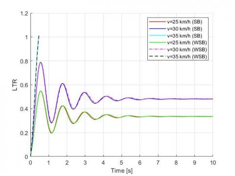
The first, the author analyzes the rollover stability characteristics in the case of a stably turning with a turn radius of 15m when the vehicle is equipped with a stabilizer bar (SB) and without it (WSB) corresponding to vehicle speeds of 25, 30, 35 km/h which it is based on the range of turning speeds mentioned in the study [21].
From the simulation results in Figure 3, it shows that the car turns around with a constant radius, when the speed increases, the tendency of the car to roll over also increases. The LTR value and the suspension displacement are proportional to the vehicle's moving speed. However, when the vehicle is equipped with a stabilizer bar, the tendency to roll over is reduced compared to without it based on the values in Table 2. At a 35 km/h of vehicle speed, the vehicle is rolled due to the value of LTR=1, at this time the vehicle is not equipped with stabilizer bar will roll sooner, the force acting on the left wheel was zero. Since the vehicle rolled at LTR=1, the value (ΨS- ΨU) did not increase anymore.
Table 2. The max value of LTR and SRA in the case of a stabilizer bar (SB) and without it (WSB) in a stably turning
|
Vehicle Velocity |
LTR (SB) |
LTR (WSB) |
SRA (SB) |
SRA (WSB) |
|
25 km/h |
0.5484 |
0.549 |
4.226 |
4.389 |
|
30 km/h |
0.7881 |
0.7888 |
6.071 |
6.306 |
|
35 km/h |
1.006 |
1.012 |
7.162 |
7.457 |
(a)
(b)
Figure 3. (a) the LTR value and (b) the suspension roll angle (SRA) of vehicle in case of a stably turning
The second, in the case when the vehicle changes lanes in the process of moving, with a lane width of 3.66m, the length of the lane changing distance is 62.14m, analysis with different vehicle speeds of 90, 100, 110 km /h which it is mentioned in the report [22] as Figure 4.
Table 3. The max value of LTR and SRA in the case of a stabilizer bar (SB) and without it (WSB) in a single lane change
|
Vehicle Velocity |
LTR (SB) |
LTR (WSB) |
SRA (SB) |
SRA (WSB) |
|
90 km/h |
0.5596 |
0.5619 |
4.305 |
4.487 |
|
100 km/h |
-0.7223 |
-0.7411 |
-5.557 |
-5.919 |
|
110 km/h |
-1.001 |
-1.004 |
-7.59 |
-7.669 |
This case is similar to the case of stable turning, the speed of the vehicle rises, the tendency of the vehicle to roll also increases, but the speed of the change lane is much larger than the speed of turning. Based on Figure 4, the vehicle is stable when traveling at a speed of 90, 100 km/h, however, according to the data in Table 3 in terms of the magnitude of the value, the vehicle equipped with a stabilizer bar has a lower tendency to roll over. When the vehicle changes lanes with a speed of 110 km/h, the LTR=-1 value, at this time the vehicle is equipped with stabilizer bar will roll later, the right wheel excitation force is zero, the vehicle is rolled, the suspension displacement value does not lift anymore after the vehicle is unstable state.
(a)
(b)
Figure 4. (a) the LTR value and (b) the suspension roll angle of vehicle in case of a single lane change
After determining the dangerous speed range, the study continues to consider the effect of the load placed on the vehicle in a vehicle equipped with a stabilizer bar, at the dangerous speed in both above cases.
From the simulation results in Figure 5, it is shown that when the load changes from no-load to full load at a dangerous speed of 35 km/h in the case of stable turning, the vehicle's rolling stability decreases with increasing load.
(a)
(b)
Figure 5. (a) the LTR value and (b) the suspension roll angle of vehicle on load change in case of stable turning
(a)
(b)
Figure 6. (a) the LTR value and (b) the suspension roll angle of vehicle on load change in case of stable turning
Similar to the case of a single lane change at a dangerous speed of 110 km/h presented in Figure 6, the results also show that the vehicle's load is inversely proportional to the vehicle's stability characteristic, the vehicle tend to roll. This has also been demonstrated by the authors in the study [23, 24].
The finally, analysis of the vehicle's rollover stability characteristics in two cases shows that the vehicle is rolled when the LTR value is ±1 while the suspension displacement value is still within the allowable range, so when analyzing the magnitude frequency response characteristics of the system in the frequency domain [19, 20], the study focuses on considering the response of the dangerous steering angle frequency to the vehicle's rollover stability when the steering angle amplitude is kept constant as shown in Figure 7.
Figure 7. The magnitude frequency characteristic of vehicle in case of single change lane
The simulation results determine that the most responsive steering angle frequency or in other words the dangerous steering angle frequency is 5.18 rad/s for the vehicle with stabilizer bar. At this frequency the vehicle tends to roll. In contrast to vehicles without stabilizer bars, the vehicle loses stability earlier at 5.09 rad/s. Based on Eq. (4), it presents that this frequency increases when the value of the total time to change lane is small, which shows that the lane change distance is not change, the change lane speed increase the larger, this time will be the smaller and easily lead to a rollover accident.
In this research, the vehicle's horizontal rollover stability dynamics model is built based on the horizontal plane of the passenger vehicle. Applying D'Alembert's principle and Runge-Kutta method to build a system of differential equations and simulate vehicle motion in the case of stable turning and single lane change from the above model.
The analysis results show that if the vehicle is equipped with a stabilizer bar that moves at a speed of less than 30 km/h when turning and below 100 km/h when changing lanes, the stability of the vehicle is guaranteed. In case the steering angle frequency reaches 5.18 rad/s, the vehicle will overturn. When the vehicle is not equipped with a stabilizer bar, the vehicle's ability to move stably is less than in the above case. Besides, the study also determined that the higher the vehicle's load, the higher the possibility of the vehicle rollover in the same moving conditions. In addition, the research results can serve to install speed warning signs or provide knowledge for drivers when moving in analytical cases.
[1] National Center for Statistics and Analysis. (2021). Early estimates of motor vehicle traffic fatalities and fatality rate by sub-categories in 2020. National Highway Traffic Safety Administration, Report no. DOT HS 813 118.
[2] Jin, Z.L., Li, J.X., Huang, Y.J., Khajepour, A. (2019). Study on rollover index and stability for a triaxle bus. Chinese Journal of Mechanical Engineering, 32: 64. https://doi.org/10.1186/s10033-019-0376-0
[3] Marimuthu, R.P., Jang, B.C., Hong, S.J. (2006). A study on SUV parameters sensitivity on rollover propensity. SAE Technical Paper 2006-01-0795. https://doi.org/10.4271/2006-01-0795
[4] Zhao, Z.G. (2014). Analysis of heavy vehicle rollover and stability. Computer Modelling and New Technologies, 18(12D): 157-161.
[5] Joshi, D., Kedia, S., Muthiah, S. (2019). A Study on the effect of steering input frequency on transient lateral dynamics of four-wheeled passenger vehicles. SAE Technical Paper 2019-26-0070. https://doi.org/10.4271/2019-26-0070
[6] Jin, Z.L., Weng, J.S., Hu, H.Y. (2007). Rollover stability of a vehicle during critical driving manoeuvres. Proceedings of the Institution of Mechanical Engineers Part D Journal of Automobile Engineering, 221(9): 1041-1049. https://doi.org/10.1243/09544070JAUTO343
[7] Sun, C., Song, S.B., Liu, Z. (2015). Vehicle roll stability analysis considering lateral-load transfer rate. 2015 International Conference on Transportation Information and Safety (ICTIS), Wuhan, China, pp. 398-402. https://doi.org/10.1109/ICTIS.2015.7232193
[8] Hassan, M.A., Abdelkareem, M.A.A., Moheyeldein, M.M, Elagouz, A., Tan, G.F. (2020). Advanced study of tire characteristics and their influence on vehicle lateral stability and untripped rollover threshold. AEJ - Alexandria Engineering Journal, 59(3): 1613-1628. https://doi.org/10.1016/j.aej.2020.04.008
[9] Moreno, G., Manenti, V., Guerero, G., Nicolazzi, L., Vieira, R., Martins, D. (2018). Stability of heavy articulated vehicles: Effect of load distribution. Transportation Research Procedia, 33: 211-218. https://doi.org/10.1016/j.trpro.2018.10.094
[10] Ojolo, S.J., Ajayi, O.O., Asuelinmen, G.A. (2020). Rollover Stability models for three-wheeled vehicle design. Arid Zone Journal of Engineering, Technology and Environment, 16(1): 92-99.
[11] Wang, M.M., Liu, J.H., Zhang, H.Y., Gan, L.J., Xu, X.B., He, J.R., Chen, S. (2021). Vehicle rollover warning system based on TTR method with inertial measurement. Measurement Science and Technology, 33(1): 015108. https://doi.org/10.1088/1361-6501/ac354b
[12] Vu, V.T., Sename, O., Dugard, L., Gaspar, P. (2016). H∞ active anti-roll bar control to prevent rollover of heavy vehicles: A robustness analysis. IFAC-PapersOnLine, 49(9): 99-104. https://doi.org/10.1016/j.ifacol.2016.07.503
[13] Nguyen, X.N., Tran, V.N., Vu, V.T., Dang, T.P. (2022). Evaluation of rollover stability of liquid tank truck in the lane change. Advances in Engineering Research and Application, ICERA 2022, Lecture Notes in Networks and Systems, Springer, Cham, 602. https://doi.org/10.1007/978-3-031-22200-9_59
[14] Kashem, S.B.A. (2013). Modeling and simulation of electromagnetic damper to improve performance of a vehicle during cornering. PhD Dissertation, Swinburne University of Technology, Hawthorn, Melbourne. http://dx.doi.org/10.13140/RG.2.2.14901.29929
[15] Moreno, G., Vieira, R., Martins, D. (2018). Highway designs: Effects of heavy vehicles stability. Dyna (Medellin, Colombia), 85(205): 205-210. https://doi.org/10.15446/dyna.v85n205.69676
[16] Sledge, N.H., Marshek, K.M. (1997). Comparison of ideal vehicle lane-change trajectories. SAE Technical Paper 971062. https://doi.org/10.4271/971062
[17] Liu, P.J., Rakheja, S., Ahmed, A.K.W. (1997). Detection of dynamic roll instability of heavy vehicles for open-loop rollover control. SAE Technical Paper 973263. https://doi.org/10.4271/973263
[18] Larish, C., Piyabongkarn, D., Tsourapas, V., Rajamani, R. (2013). A new predictive lateral load transfer ratio for rollover prevention system. IEEE Transactions on Vehicular Technology, 62(7): 2928-2936. https://doi.org/10.1109/TVT.2013.2252930
[19] Vu, V.T., Sename, O., Dugard, L., Gaspar, P. (2017). Enhancing roll stability of heavy vehicle by LQR active anti-roll bar control using electronic servo-valve hydraulic actuators. Vehicle System Dynamics, 55(9): 1405-1429. https://doi.org/10.1080/00423114.2017.1317822
[20] Tran, V.N., Nguyen, X.N., Vu, V.T., Dang, T.P. (2022). Rollover stability analysis of liquid tank truck taking into account the road profiles. Journal of Applied Engineering Science, 20(4): 1133-1142. https://doi.org/10.5937/jaes0-36578
[21] Jagelčák, J., Gnap, J., Kuba, O., Frnda, J., Kostrzewski, M. (2022). Determination of turning radius and lateral acceleration of vehicle by GNSS/INS sensor. Sensors, 22(6): 2298. https://doi.org/10.3390/s22062298
[22] Federal Highway Administration. (2017). Speed Limit Basics. U.S. Department of Transportation, FHWA-SA-16-076.
[23] Xu, J.L., Xin, T., Gao, C., Sun, Z.H. (2022). Study on the maximum safe instantaneous input of the steering wheel against rollover for trucks on horizontal curves. International Journal of Environmental Research and Public Health, 19(4): 2025. https://doi.org/10.3390/ijerph19042025
[24] Ito, K., Fujishiro, T., Kanai, K., Ochi, Y. (1990). Stability analysis of automatic lateral motion controlled vehicle with four wheel steering system. In Proceedings of the 1990 American Control Conference, San Diego, CA, USA, pp. 801-808. https://doi.org/10.23919/ACC.1990.4790842