Ahmad Yuhani | Isdaryanto Iskandar | Arief Goeritno* | Ika Setyawibawa | Gatot Eka Pramono | Yuggo Afrianto
© 2022 IIETA. This article is published by IIETA and is licensed under the CC BY 4.0 license (http://creativecommons.org/licenses/by/4.0/).
OPEN ACCESS
This article explains about a stage after the stage of the verification test, there is a phase of a form of prior activity to the final stage, i.e., the hot commissioning phase. Hot commissioning is a stage for providing a realistic condition or validation test activity. Based on the follow-up activity which is the reason for choosing the title, therefore the two research objectives in this article are set. The first objective is to create conditions for the system when the end user controls through the radio-based electronic device, whereas the second objective is to create conditions for the system when the end user controls through the telephony-based electronic device. The steps of research methods for achieving the research objectives are carried out through (i) calling activities, (ii) connecting process, and (iii) disconnecting activities after obtaining a connection to communicate from a radio-based device (using the handy talky, HT) and from the telephony-based device (used the mobile phone). The two results based on research objectives have been obtained after observation regarding activities of calling activity, making telephone calls, and termination activity after connecting from radio-based and telephony-based devices. Based on the research results, it can be concluded that the half duplex-based interface device for communicating (IDC) functioned after the realistic conditions is given.
a half-duplex system, a realistic condition, interface device for communicating, observing the performance
The ideas and activities of this research are based on previous research which has been published [1, 2], namely (i) an electronic device reviewed by diagnosing the embodiment of the module [1] and (ii) designing a microcontroller-based half-duplex interface device driven by the touch-tone signal [2], therefore this research is a follow-up activity in the form of observing the performance of the equipment after the verification tests have been carried out in the previous article [2]. The final result comes from manufacturing or assembling and is an integral part of the new product or product development process are require verification and validation tests [3]. Both tests are mandatory tests, only the first is a verification test. A verification test is more critical than a validation test, because if a verification test fails, then a validation test cannot be carried out. Several of these explanations are the reasons for choosing the title.
Several state-of-the-art related studies are described to support the paragraph on the reason for choosing the title. An electronic device is the result of manufacture or assembly, then a verification test is needed because it has always been and will always be [4]. A verification test is a form of cold commissioning, prior to the stage of hot commissioning [5]. Cold commissioning is an implementation stage which is also known as the process of implementing a simulation, which is to provide artificial conditions as if they were real events. Hot commissioning is the stage of providing a realistic condition is better known as a validation test activity [6]. The typical verification testing activities for electronic assembly or manufacturing products include unity and integration testing [4, 7].
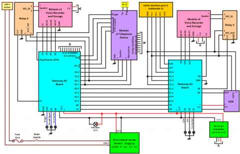
A piece of electronic device for communicating as a connecting device between two devices with different protocols [8-10] i.e., the radio-based and the telephony-based systems has become a necessity [11]. The radio-based communication system is known as a radio communication system (RCS) or radio-frequency system (RFS) [12-15], whereas the telephony-based communication system is known as a public switched telephone number (PSTN) or global system for mobile communication (GSM) [16-20]. The connecting device is better known as the IDC and the term interface device for communicating (IDC) is previously known as communication interface adapter (CIA) [1, 2]. The stage of the verification test has been published with the product design against its specifications [4]. This ensures that the design and each unit of the IDC is produced and meets its specifications and can be delivered to its processing on the cold commissioning [7]. The product design against its specifications of IDC includes designing, manufacturing, assembling, and diagnosing [1, 4]. The relationship between these stages is a sequence of processes which is the starting from the initial phase in the form of pouring ideas, designing tools, assembling electronic circuits, processes of wiring for assembling and integrating, and the final process in the form of realizing the electronic device. All stages are for comprehensive details to investigate the performance [21] of the IDC. The designing stage is to obtain several electronic circuits as a liaison, the manufacturing stage is to obtain the printed circuit board, the assembling stage is to obtain the gateway boards controlled by the boards Arduino, and diagnosing stage is to obtain the IDC formed by integrating the wiring [1]. Integrating several electronic circuits, modules, and devices have resulted in an IDC. Operating the IDC uses two different systems, i.e., from the telephony-based system to the radio-frequency system or vice versa with a half-duplex mechanism [2] assisted by the microcontroller, where the microcontroller is the central controller of the system [22-25]. The block diagram of the relationship between modules on the half duplex-based IDC assisted by the boards Arduino, i.e., UNO R3 and MEGA2560 R3 [1, 2] is shown in Figure 1.
Figure 1. The block diagram of the relationship between modules on the half duplex-based IDC assisted by the boards of Arduino, i.e., UNO R3 and MEGA2560 R3
The form of verification test activity [7] has also been carried out on the half duplex-based IDC that was obtained from the results of design and manufacturing. The verification test includes that have conducted a number of tests on the circuits of the ring detection, the VOX, the telephone module for “off-hook condition”, and the tone decoder. Continuing with making a dial-up telephone number via the DTMF button and the IC switching circuit, also testing the circuits of sound recorder and storage in the form of voice recording and playback [2]. The ring detection result is in the form of a measured value of voltage when there is no incoming call. The voice signal can be detected by the circuit of the VOX with a minimum voltage level of 2.314 millivolts as a sign that the circuit is operating properly. Simulation of the off/on-hook circuit is carried out by treating telephone calls from radio devices, then measuring the relay pins [1, 2]. The verification test on the tone decoder circuit is in the form of giving an input signal of 450 hertz from a digital radio test set at the input pin of the tone decoder circuit. The results of the DTMF circuit verification test are in the form of a response to the DTMF signal that enters the input line pin according to the keypad button that is pressed [2]. Provision of conditions for the sound recorder and storage circuit in the form of the number of sounds that can be recorded on the sound recorder and storage circuit and the condition of the system when the sound reappears [4]. Based on these results, validation test activities were carried out for the final stage.
Figure 2. The schematic diagram of the problem formulation
Based on a number of paragraphs regarding the state-of-the-art previous research, which is related to the design and manufacture as well as when the verification test is carried out, it is necessary to carry out an advanced stage as the final stage in the form of a validation test process against the results of previous research [4, 7]. The formulation of the problem in this paragraph is in the form of a sequence of processes starting from the initial phase in the form of pouring ideas, designing tools, assembling electronic circuits, processes of wiring for assembling and integrating, and the final process in the form of realizing the electronic device [1, 4]. The second phase is the process of providing artificial conditions through the implementation of simulations or the provision of cold commissioning (verification tests) [2, 4, 7]. The final stage is the implementation of the validation test [4, 7]. The entire process is made in the form of a schematic diagram of the sequential and continuous processes [7]. The schematic diagram of the problem formulation is shown in Figure 2.
Based on Figure 2, it can be explained, that the first stage of research realization refers to the results of research that has been disseminated [1], while the second stage of research realization refers to the result of research that has also been disseminated [2]. The first stage of research realization namely the idea, design of electronic devices, and adoption of the operating mechanism of a system in the form of the physical realization of the half duplex-based IDC. The second stage of research realization is the verification test which includes (i) the circuit of ring detection, (ii) the circuit of voice-operated transmit, (c) the circuit of telephone module “off-hook condition”, (d) the circuit of tone decoder, (e) make a dial-up telephone number via dual-tone multi-frequency button and the integrated circuit for switching circuit, and (f) the circuits of sound recorder and storage in the form of voice recording and playback.
For the realization of the final stage in the form of a validation test, in this paper two research objectives are set, namely to create conditions for the system when the end user controls radio-based and telephony-based electronic telecommunication devices, therefore that both conditions can be monitored and measured, and so that the electronic device as a result of this assembly can produce a performance as expected. The process when the end user controls from a radio-based communication device is carried out through calling activities and connecting the telecommunications process from a radio-based device using the HT and disconnecting activities after obtaining a connection to communicate. The process when the end user controls from a telephony-based communication device is carried out through call activities and telecommunication connection from a telephony-based communication device using the mobile phone and disconnection activities after a connection is obtained to communicate.
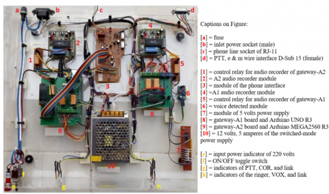
The two most important research materials of this observation are the two research results that have been disseminated, i.e. (i) an electronic device reviewed by diagnosing the embodiment of the module [1] and (ii) designing a microcontroller-based half-duplex interface device driven by the touch-tone signal [1]. The integration of the half duplex-based IDC as the embodiment of the module through the integrated wiring [1, 2] is shown in Figure 3.
Figure 3. The integration of the half duplex-based IDC as the embodiment of the module through the integrated wiring
Figure 4. The flowchart of the research methods
The methods of research are an algorithm of a researcher for conducting the research that is carried out in the form of stages to achievement [1, 2, 25-28], and which is guided by the research objectives. In other words, some stages must be carried out sequentially the objectives [1, 2, 26, 28] so this research method is made in the form of a flow chart, and under steps for achieving each research objective [2, 26, 28]. The flowchart of the research methods is shown in Figure 4.
A validation test is in the form of measuring system performance which is carried out on the system when the end user is controlling activity from the radio-based device or from the telephony-based communication device. In this chapter, two main topics related to the research objectives are discussed, i.e. monitoring the condition of the system when (i) the end user is controlled by the radio-based communication devices and (ii) the end users are controlled by telephony-based communication devices, i.e., PSTN or GSM.
3.1 The condition of the system when the end user is controlled by the radio-based communication device
The end user activities can be carried out through several controls with DTMF signals at the minimum system. The control can be carried out with radio-based communication devices that are explained, i.e., i) calling activity and making telephone calls from radio-based device and ii) termination activity after connecting.
3.1.1 Calling activity and making telephone calls from a radio-based device and using the handy-talky
For telephone call activities by end users, it must be done by pressing the 02# button simultaneously pressing the PTT button on the HT device, with the voice stored at address 0000 1111 in the voice recorder and storage circuit in the module of gateway-A1 is played with the sound “02 is connected, enter a phone number, end with a hash mark (#)”. For conditions in which the end user presses a key other than 02#, the sound stored at address 0000 0000 on the recorder and storage circuit is played with a “slot not available” sound so the 02# keypress step must be repeated as described previously. Furthermore, if the 02# key has been pressed correctly and after the sound “02 is connected, enter the phone number, end with a hash mark (#)”, the end user returns by pressing the PTT button on the radio device followed by pressing the button of the destination telephone number that ends with a hash sign (#).
With regard to the presence of the microcontroller in the modules of gateway-A1 and gateway-A2 are connected to each other on the TX/RX data communication pin according to the program, the response of the microcontroller in the module of gateway-A2 is activating the on/off hook relay, and relays on the loudspeaker line and microphone line relay. For conditions where the tone is 450-hertz, the tone decoder circuit is detected, therefore the activation of the output pins D44–D53 by the microcontroller is sequentially according to the pressing of the telephone number of the HT device. Based on this, calls to the dialed telephone number are made by the telephone module. Communication can be done when the call is received. For conditions where a dial tone with a frequency of 450-hertz is not detected by the tone decoder circuit, the sound stored at the address of 1111 0011 on the voice recorder and storage circuit is played with a "disconnected" sound, and according to the program made all the circuits contained in a minimum the system returns to the initial position and is ready to respond to the input given by the next end user, either from radio frequency-based communication devices or from telephony-based communication devices.
The display condition when the modules of gateway-A1 and gateway-A2 are connected is shown in Figure 5.
Figure 5. The display condition when the modules of gateway-A1 and gateway-A2 are connected
3.1.2 Termination activity after connecting when using the handy-talky
Disconnection of the communication connection from radio-based communication devices can be done if the condition of the system is connected. To disconnect the connection between the radio-based communication system and the telephony-based communication system is done by pressing the PTT button, followed by pressing the “*” (star) button from the HT device. The voice at address 1111 0011 on the sound recorder and storage circuit is played with a "disconnected" sound, and according to the program made all the circuits contained in the minimum system return to the initial position and are ready to respond to the input given by the end user, then either from radio frequency-based communication devices or from telephony-based communication devices. Display of the initial condition when the modules of gateway-A1 and gateway-A2 after disconnection is shown in Figure 6.
Figure 6. Display of the initial condition when the modules of gateway-A1 and gateway-A2 after disconnection
3.2 Monitoring the condition of the system when end users are controlled by the telephony-based communication device
End user activities can be carried out with several controls based on DTMF signals at the minimum system. Controls that can be carried out with a telephony-based device can be explained, i.e., (i) calling activity and making telephone calls from a telephony-based device and ii) termination activity after connecting.
3.2.1 Dialing activity and connecting telephone calls from the telephony-based device and using the mobile phone
For connecting the mobile phone to the end user of handy-talky, telephone calls must be made to the telephone number that is used as a gateway on a minimum microcontroller-based system. When there is a ringing tone three times in a row, the microcontroller in the module of gateway-A2 responds to the tone by activating the off-hook relay, therefore that the telephone module is in a state of receiving incoming telephone calls. The follow-up operation is in the form of forming binary data of 0000 1111 by a series of voice recording and storage through activating pins A0-A7 so that the sound "input slot number" is heard by a series of voice recorders and storage, then the 01# button is sequentially pressed by the end user so that it is connected to the radio-based device. For conditions where the end user is not pressing the 01# key in sequence, the pins of A0-A7 of the sound recording and storage circuit are activated by the microcontroller, therefore that binary data of 0000 000 is formed so that the sound "slot is not available" is heard by the sound recorder and storage circuit. For conditions where until the specified time the button is not pressed according to the end user program, the off-hook relay is deactivated by the microcontroller so that 1111 1100 binary data is formed. The next condition is activating pins A0-A7 of the sound recording and storage circuit so that the sound is "disconnected” is heard by a series of voice recorders and storage so that the system returns to a state ready to receive another phone call. For conditions where the appropriate button has been pressed, the modules of gateway-A1 and gateway-A2 are connected and communication between handy-talky and mobile phone communication devices can be carried out.
3.2.2 Termination activity after connecting when using the mobile phone
To disconnect communication from telephony-based communication devices, the end user needs to do this by pressing the “*” (star) button from the DTMF keypad. For conditions where a "*" (star) button is detected by the module of gateway-A2 when the modules of gateway-A1 and gateway-A2 are connected, the microcontroller responds by activating the A0-A7 pins of the voice recording and storage circuit, therefore that binary data 1111 1100 is formed, and a "disconnected" sound is heard. In accordance with the program made, all the circuits contained in the minimum system return to their initial position and are ready to respond to the input given by the next end user, either from radio-based devices or from telephony-based devices.
Based on the results and discussion guided by the research methods, therefore conclusion can be drawn according to the research objectives in this paper. The provision of actual conditions for the half duplex-based IDC has functioned, after observing the provision of the realistic conditions, namely monitoring the condition of the system when end users control by using the radio-based and/or telephony-based telecommunications types of equipment. In general, after the electronic device as a result of this assembly can be used and produces a performance, it is expected that the system is well connected perfectly.
Completing the conclusion, recommendations for future work related to activities and processes for assembling and manufacturing the IDC based on full-duplex transmission mode. Many benefits can be obtained from the realization of these systems and devices. Unlike a half-duplex, in a full-duplex communication mode, two parties communicating with each other will send information and receive information at the same time, and generally requires two communication lines. Full-duplex transmission mode can also be achieved using multiplexing techniques, in which signals traveling in different directions are placed in different time slots. The downside of this technique is that it cuts possible transmission speeds in a half.
|
HT |
Handy-Talky |
|
IDC |
Interface Device for Communicating |
|
RCS |
Radio Communication System |
|
RFS |
Radio-frequency System |
|
PSTN |
Public Switched Telephone Number |
|
GSM |
Global System for Mobile Communication |
|
CIA |
Communication Interface Adapter |
|
VOX |
Voice Operated Transmit |
|
DTMF |
Dual-Tone Multi-Frequency |
|
IC |
Integrated Circuit |
|
PTT |
Push To Talk |
|
TX/RX |
Transmitter/Receiver |
[1] Goeritno, A., Setyawibawa, I. (2021). An Electronic Device Reviewed by Diagnosing on the Module Embodiment. International Journal of Electronics and Communications System, 1(2): 41-55. http://ejournal.radenintan.ac.id/index.php/IJECS/article/view/10383/pdf.
[2] Goeritno, A., Setyawibawa, I., Suhartono, D. (2021). Designing a microcontroller-based half-duplex interface device drove by the touch-tone signal. Jurnal Infotel, 13(4): 205-215. https://dx.doi.org/10.20895/infotel.v13i4.712
[3] Raudberget, D.S. (2015). Industrial application of set-based concurrent engineering–managing the design space by using platform system families. Chalmers Tekniska Hogskola (Sweden).
[4] Tahera, K., Wynn, D.C., Earl, C., Eckert, C.M. (2019). Testing in the incremental design and development of complex products. Research in Engineering Design, 30(2): 291-316. https://doi.org/10.1007/s00163-018-0295-6
[5] Bhunia, S., Tehranipoor, M. (2019). System on Chip (SoC) Design and Test. Hardware Security, pp. 47-79. https://dx.doi.org/10.1016/b978-0-12-812477-2.00008-3
[6] Zemliak, A. (2018). Analysis of strategies of circuit optimisation on basis of maximum principle. COMPEL-The International Journal for Computation and Mathematics in Electrical and Electronic Engineering, 37(1): 484-503. https://dx.doi.org/10.1108/compel-12-2016-0540
[7] Shankar, P., Summers, J.D., Phelan, K. (2017). A verification and validation planning method to address change propagation effects in engineering design and manufacturing. Concurrent Engineering, 25(2): 151-162. https://doi.org/10.1177/1063293X16671771
[8] Yu, Y., Zheng, L., Zhu, J., Cao, Y., Hu, B. (2018). Technology of short-distance wireless communication and its application based on equipment support. In AIP Conference Proceedings, 1955(1): 040135-040135. https://doi.org/10.1063/1.5033799
[9] Yang, S.M.M. (2020). Overview of Radio Communication Signals and Systems. In Modern Digital Radio Communication Signals and Systems, Springer, Cham, pp. 1-32. https://doi.org/10.1007/978-3-030-57706-3_1
[10] Asplund, H. Astely, D., Butovitsch, P.von., Chapman, T., Frenne, M., Ghasemzadeh, F., Hagström, M., Hogan, B., Göngren, G., Karlsson, J., Kronestedt, F., and Larsson, E. (2020). Radio performance requirements and regulation. advanced antenna systems for 5G network deployments. Cambridge, MA: Academic Press, pp. 453-525. https://dx.doi.org/10.1016/b978-0-12-820046-9.00011-3
[11] Abiad, M., Kadry, S., Ionescu, S. (2018). Cost efficiency of Telecommunication Equipment-A Review. In 2018 4th International Conference on Applied and Theoretical Computing and Communication Technology (iCATccT), Mangalore, India, pp. 275-280. https://dx.doi.or/10.1109/icatcct44854.2018.900
[12] ITU. (2020). The Radio Regulations, Edition of 2020. ITU Publication Notice, 2020.
[13] Mishra, A., Alexander, T. (2015). Radio communications: Components, systems and networks [Series Editorial]. IEEE Communications Magazine, 53(3): 189-189. https://dx.doi.or/10.1109/MCOM.2015.7060503
[14] Hwang, C. (2018). RF Desensitization in Wireless Devices. In RF Systems, Circuits and Components. IntechOpen, pp. 101-118, http://dx.doi.org/10.5772/intechopen.76162
[15] Bensky, A. (2019). Radio system design. Short-Range Wireless Communication: Fundamentals of RF System Design and Application, 163-198, https://dx.doi.org/10.1016/b978-0-12-815405-2.00007-5
[16] Rahman, A., Mahmud, M., Iqbal, T., Saraireh, L., Kholidy, H., Gollapalli, M., Musleh, D., Alhaidari, F., Almoqbil, D., Ahmed, M.I.B. (2022). Network anomaly detection in 5G networks. Mathematical Modelling of Engineering Problems, 9(2): 397-404. https://doi.org/10.18280/mmep.090213
[17] Comina, G., Suska, A., Filippini, D. (2016). Towards autonomous lab-on-a-chip devices for cell phone biosensing. Biosensors and Bioelectronics, 77: 1153-1167. https://dx.doi.org/10.1016/j.bios.2015.10.092
[18] Donald, E., Favour, O.N. (2021). Analysing GSM Insecurity. arXiv preprint arXiv:2109.12408. https://doi.org/10.48550/arXiv.2109.12408
[19] Kędzior, K. (2018). Introduction to human factors and ergonomics. International Journal of Occupational Safety and Ergonomics, 24(1): 1-1. https://dx.doi.org/10.1080/10803548.2018.1463724
[20] Nyangaresi, V.O., Abeka, S.O., Anthony Rodgrigues, A. (2018). Security evaluation of cellular networks handover techniques. International Journal of Computer Network and Information Security (IJCNIS), 10(5): 45-59. https://dx.doi.org//10.5815/ijcnis.2018.05.06
[21] Ghith, E.S., Tolba, F.A. (2022). Real-time implementation of an enhanced PID controller based on ant lion optimizer for micro-robotics system. Mathematical Modelling of Engineering Problems, 9(4): 1113-1122. https://doi.org/10.18280/mmep.090430
[22] Massimo, B., Shiloh, M. (2015). The Arduino Paltform. Getting Started with Arduino, 3rd edition. Sebastopol, CA: Maker Media, 15-22.
[23] Güven, Y., Coşgun, E., Kocaoğlu, S., Gezici, H., Yılmazlar, E. (2017). Understanding the concept of microcontroller based systems to choose the best hardware for applications. Research Inventy: International Journal of Engineering and Science, 7(9): 38-44. http://acikerisim.klu.edu.tr/xmlui/handle/20.500.11857/1024.
[24] Goeritno, A., Irawan, J., Sopyandi. (2018). Segmentation of load groups on a single phase kwh-meter using the payload data handling system. International Journal of Advanced Research (IJAR), 6(7): 415-426. https://dx.doi.org/10.21474/IJAR01/7378
[25] Goeritno, A., Afandi, M.Y. (2019). Designing a security system based-on microcontroller integrated into the immobilizer system. International Journal of Electronics and Communication Engineering, 6(8): 1-11. https://dx.doi.org/10.14445/23488549/IJECE-V6I8P101
[26] Goeritno, A., Nurmansyah, D., Maswan. (2020). Safety instrumented systems to investigate the system of instrumentation and process control on the steam purification system. International Journal of Safety and Security Engineering, 10(5): 609-616. https://doi.org/10.18280/ijsse.100504
[27] Goeritno, A., Nugraha, I., Rasiman, R., and Johan, A. (2020). Injection current into the power transformer as an internal fault phenomena for measuring the differential relay performance. Instrumentation Mesure Metrologie, 19(6): 443-451. https://dx.doi.org/10.18280/i2m.190605
[28] Prayudyanto, M.N., Goeritno, A., Al Ikhsan, S.H., Taqwa, F.M.L. (2022). Designing a model of the early warning system on the road curvature to prevent the traffic accidents. International Journal of Safety and Security Engineering, 12(3): 291-298. https://dx.doi.org/10.18280/ijsse.120303