Nattan Roberto Caetano | Augusto Botton Pozzebon | Louise Bomfim Magalhães França | Nátali Schmidt Gonçalves da Conceição | Andressa Germann Ávila | Luiz Alberto Oliveira Rocha | Giulio Lorenzini*
© 2022 IIETA. This article is published by IIETA and is licensed under the CC BY 4.0 license (http://creativecommons.org/licenses/by/4.0/).
OPEN ACCESS
This work aims to evaluate the possibility of adding obstacles to ducts with isothermal flows and their effects on the performance of the flowfield. This literature review was performed based on several articles exploring obstacles and their geometries inside ducts and chambers or channels and analyzing the obstacle distribution in a nozzle. The main utility of the obstacle is in the pipes and boilers of the metal-mechanical and petrochemical industry. In these industries, results are mostly positive since the obstacles allow manipulating the temperature inside channels and on their walls. Besides, they are correlated to increasing the acceleration of the exhaust gases and turbulence of the flow. In addition, an optimal preliminary nozzle geometry was found for applications in the aerospace industry. However, this information is useful for other applications. Thus, the possible use of obstacles in cases where the combustion reactions are considered seems promising, indicating an excellent opportunity to further research this topic in more specific areas.
duct, inside, obstacles turbulator
An important challenge for this century is producing energy based on sustainable modals and high-efficiency applications. Thus, the production, conservation, and use of energy using advanced equipment and the use of more efficient technologies are not only the subject of various research funds, but also they keep engineers working in search of optimized systems.
Energy efficiency in thermal industries is a constant search in which engineers strive to design and optimize existing systems and develop new devices to meet industrial demand – both for better heat exchangers and high-performance flow equipment. This effort led to the design of numerous innovative applications, mainly for power generation and transmission systems, petrochemical plants, reaching up to, and mainly in, the mobility industry. Thus, many studies have been conducted to examine the aerodynamic and thermo-hydraulic performance, especially in cylindrical pipes and in ducts of different shapes, while using internal obstacles.
The use of obstacles or promoters of turbulence inside pipes has been studied since the 1980s, when Han et al. [1] used repeated fins arranged in a turbine cooling system to improve the heat transfer of the system. They sought to determine how the angle of attack of the fins influenced the pressure drop and heat transfer coefficients in a fully developed and turbulent flow, varying the Reynolds number of the fluid. The experimental/numerical results show that when using turbulence generators in pipes to change the pressure drop, a fluidity gain arises, and it is possible to reduce the pumping cost or exhaust flow. Additionally, heat exchange and thermal stress on the pipe wall are affected.
An efficient technique for increasing heat transfer is needed to improve heat transfer significantly and minimize resistance to coolant flow. Thermo hydraulic performance is often improved by modifying the surface patterns of the heat transfer flaps/fins downstream of the flow.
According to information available in the literature, the use of obstacles improved heat transfer in fluid flow. These obstacles are also called artificial roughness: pits [2, 3], furrows [4, 5] or fins [6, 7]. These perturbations affect airflow, provide a three-dimensional mixture of fluids, and generate counter-rotating transverse/longitudinal vortices.
The increased heat transfer using these techniques leads to considerable growth in flow resistance, which affects the cost of operation, with a higher cost in pumping power due to augmented frictional load loss. Several researchers have devoted their time to designing a channel with obstacles to improve heat transfer with minimal load loss by adopting numerical and experimental methods. Most experiments are also carried out to provide data on the geometric parameters of such obstacles on flow characteristics and heat transfer of the flows in turbulence-generating ducts. Turbulated surfaces have a higher heat transfer coefficient and a larger area for heat transfer due to the artificial roughness of the surface.
Yakut and Sahin [8] investigated the effect of tapered son heat transfer, pressure drop, and fluid flow-induced vibrations in turbulent flows. Anvari et al. [9] reported the effect of the tapered on heat transfer using water as a test liquid. Promvonge and Eiamsa-ard [10] investigated the effect of heat transfer on the combined conical ring and twisted tape (spring shape) for twisting relationships ranging from 3.75 to 7.5. Bhattacharyya et al. [11] investigated experimentally and numerically the heat transfer and fluid flow properties for turbulent flows of a heat exchanger mounted with a twisted circular tube. Kapse et al. [12] experimentally studied heat transfer and pressure drop properties of three different passive combinations for individual and composite addition. The obstacles provided a 77% increase in heat transfer and an increase in friction factor 3.3 times compared to the empty tube.
Several studies have investigated the design modification of heat transfer enhancement devices, which can significantly affect heat transfer rate and friction factor. The helical spring format (twisted tape) showed better results, encouraging new research to improve the design further. Another study considered convergent-divergent springs with a circular cross-section. It was noticed that the conical shape and the convergent-divergent section affected heat transfer in a turbulent flow [12].
Obstacles are employed in a wide variety of heat exchange applications, such as heat exchangers [13], gas turbine blade cooling devices, solar air heaters [14], and cooling devices for electronic components [15]. Thus, many studies have been conducted to examine the effects of obstacles on increased heat transfer. It is worth noting that the obstacles can take on the most diverse geometric and volumetric shapes, most of which are detailed in Refs. [15, 16]. The main two-dimensional formats used in numerical analyses are circular, quadrangular, and triangular with varied angles. On the other hand, the models used in the industry in the heat exchanger ducts are the sphere, springs and helical blades shaped obstacles.
Disturbances in the flow can also be generated by inserting angled flows in relation to the main axis of the flow [17]. Since such elements are usually subjected to severe temperature and pressure conditions, as well as cyclic loading, which can lead to fatigue failure, it is recommended to use materials with high fatigue resistance, which have a high melting point and are tenacious [18, 19].
This section intends to present the main mechanical and structural characteristics of pipes in applications with severe conditions, high pressure, high temperature, high fluid corrosiveness, etc., and how to understand the mechanical stresses to which the channels are subjected. In summary, the considerations and results obtained are presented.
With the advent of steam machines and their use for transporting energy through pipes, it was necessary to improve the design of these systems, which generated the demand for materials with improved mechanical properties, reliable manufacturing processes, and robust assembly. Ducts with smooth walls and free of obstructions were sought since these generate load losses in the fluid. As the application of fluid systems became more comprehensive, for example the use of gas turbines for power generation, it was noticed that obstacles in the pipelines could improve the efficiency of these mechanisms in some applications.
Currently, obstacles in pipes are widely used in the metal-mechanical industry, aiming to increase the efficiency of heat exchangers, mixers, boilers, gas turbine blades, and jet propulsion turbines in the case of the aerospace industry. For the simplest cases, in use in heat exchangers, obstacles are found commercially in several different shapes and materials, such as spheres, springs, and wires, which can be made of aluminum, brass, alloy iron, carbon steel, brass, copper, monel and stainless steel; materials that present as a common factor the resistance to corrosion and heat.
Analyzing the study of a heat exchanger, it is remarkable that the heater piping reached temperatures between 307 and 998 Kelvin, which signals that the materials used for these applications must have a high melting point. In the studies [18, 19], obstacles were used in combustion chambers that reached temperatures of up to 1659 K.
Xiao and Oran [16] and Buchanan [20] show that the nozzle material is usually a metal or carbon compound capable of supporting high temperatures and the melting point of the most frequently used metals. When heated by the hot gas environment, the heat passes through the nozzle and radiates close to the outer surface, so only the nozzle or its extensions are made to be cooled by transferring heat by radiation into large liquid-propelled rockets since the material from which they are made is not tough enough to be used in the combustion chamber [21].
De Oliveira [22] tests a series of materials and alloys with coatings used in the manufacture of nozzles with hybrid propellant, having as objective the use of CuCr alloys with ceramic coatings to act as a thermal barrier in the construction of a nozzle. Tests with carbon-carbon and graphite nozzles, among other materials, were also performed and compared, making this research comprehensive and conclusive to specify that the materials that make up the rocket nozzle have adequate resistance to high temperature and pressure, as demand for the manufacture and use of obstacles in rocket engines.
The concern with selecting materials is important; however, it is worth mentioning an advantage. Studies such as Barcelos and Centeno [18] and Darbandi and Ghafourizadeh [19] show that the temperature and pressure decreased by including obstacles in the structure. The more resistant a material needs to be to a certain factor, the more expensive it becomes. However, the application of obstacles proved to reduce these requirements for the materials used. This way, there can be a greater possibility of variation in the materials.
In this section, studies are summarized regarding the main geometries of obstacles, as well as the main changes in the flow due to the insertion of such devices.
The reviewed papers studied the implementation of obstacles in pipelines, refrigerators, and types of CAD modeled pipes. The objective of the revised items was to analyze and quantify which factors change when inserting obstacles and when there are changes in conditions such as temperature, acceleration, pressure, etc., analyzing whether varying the geometry of obstacles would result in another parameter change.
From the analysis of the impacts of different 2D shapes and injector geometries in the generation of turbulence and improvement of essential factors, such as velocity and acceleration of gases, as well as the transition from deflagration to detonation (TDD), it is possible to infer that square and triangular shapes favor the flame structure, facilitating its propagation. As a result, they cause an improvement in flame acceleration and TDD, while circular obstacles negatively affect the flame structure, reducing gas acceleration and delaying DDD due to flame suffocation. The geometries discussed here will be better explained with numerical results in the following topics.
Kumar and Sahu [23] varied the size of the coaxial injector nozzle, the area ratio through which the fluid is injected (Fluid Area Ratio - AR), and the ratio of thickness in the exit (Lip Thickness Ratio - LTR), seeking to find the influence of nozzle geometry in various flow instabilities. It was observed that fluctuations in the separation length of the jet, which, unlike the average length (little influenced by the geometry of the nozzle), suffer an impact directly proportional to the moment ratio or inversely proportional to the LTR. The frequency of Kelvin-Helmholtz instability, which considerably influences the velocity of gases, was favored by LTR, suffering from the impact of AR.
According to the authors, this is due to the separation in the airflow near the injector outlet, generating divortexes. Taslim and Springt [24] also evaluated the effects of AR from obstacles located in the cooling passages of small turbine blades, concluding that obstacles with AR < 1 produce lower heat transfer coefficients than those with AR > 1, although these have high-pressure losses. According to them, the optimal shape is trapezoidal, as long as the obstacles are distributed correctly, as they present moderate pressure losses maintaining good heat transfer coefficients. Kim et al. [25] also evaluated the changes in heat transfer coefficient as a function of geometric parameters of fin obstacles, more specifically the angle of attack (α) of the fin and height (w/e), finding better results in the ranges 50≤ α ≤60 and 6.0≤ p/e ≤7.0, with higher heat transfer rate at α =53.31 and p/e =6.50 and better thermal performance at α =54.67 and p/e =6.80.
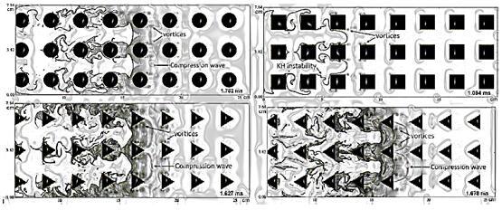
The test done by Xiao and Oran [16] was to analyze the acceleration of the flame in a channel with a mixture of hydrogen-air made in 2D with obstacles in different ways. Thus, circular geometry produced 15% distance, 27% time, 9.84% speed, and 41.34% acceleration less than square geometry for the Time of TDD. Therefore, it has the smallest effect as an obstacle in a duct. The square obstacles caused the best results for the beginning of the TDD moment, with a distance of 0.309 m, time of 0.001626 s, speed of 190.0369 m/s, and acceleration of 116873.8622 m/s2, these being the highest growth rate of the flame surface in the flame acceleration phase, resulting in greater flame acceleration and shorter TDD start time than circular or triangular obstacles, as shown in Figure 1.
Figure 1. Time and distance to detonation, adopted from [16]
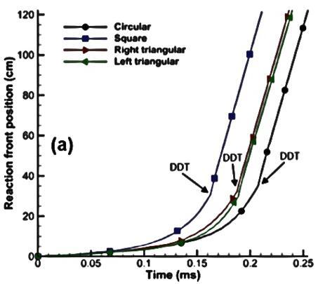
In quantitative terms, it is important to highlight the maximum and minimum results for time and distance for the occurrence of detonation, illustrated in Figure 2. In this sense, the shorter time of TDD start was obtained by the square (1.626 ms), while the largest was by the circle (2.072 ms), with a difference of 27%. Regarding the distance from the input section to the position where the detonation began, the smallest was 0.309 m, while the largest was 0.355 m, with a difference of 15%, caused by the square and circle, respectively.
Seeking to understand the effect of the shape of the obstacle on flame acceleration and TDD, Xiao and Oran [16] performed two-dimensional numerical simulations involving four shapes: circles, squares, and triangles with sharp left and right angles, maintaining the same blocking ratio.
The results in the case of circular obstacles show that the TDD results from the shock focused on the front of the flame. The higher blocking between the characteristic length of the body under analysis and the length associated with the test section leads to faster flame acceleration. It facilitates flame suffocation, generating heat losses that significantly attenuate flame acceleration and delay the start of detonation.
Figure 2. Position and propagation speed, adopted from [16]
Finally, the triangular obstacles were similar in relation to the total flame propagation and the TDD, with only a minimum difference, less than 0.05 m, at the beginning of the detonation. A more detailed analysis pointed out that triangular objects, compared to circular obstacles, are more conducive to the elongation and propagation of the flame due to their acute angles and, therefore, facilitate flame acceleration and TDD.
Where to position the obstacles is an essential question. It was possible to analyze different experiments involving obstacles placed in different locations and articles that made this comparison between the positions, either by changing places or increasing the blocking ratio. Positioning can be at the beginning or end of a standard duct or with different spacings. All of these possibilities will generate different results, analyzed below.
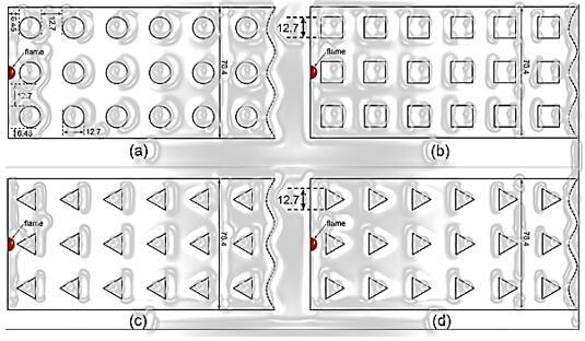
Despite the information gap, Xiao and Oran [16] took positioning into account while doing analyses on a detonation tube with different obstacle geometries, placing them evenly spaced, as illustrated in Figure 3. The analysis was performed with a channel of 76.4 mm in height aligned parallel to the direction of flame propagation. This configuration was used to simulate the experiment of Pinos and Ciccarelli [26], who performed a three-dimensional experiment in the same proportions of diameter, height, and width, coming to results with a considerable agreement.
Figure 3. Pipe sizing and geometry, adopted from [16]
Kostić et al. [27] evaluated the possibility of inserting obstacles into the nozzle outlet, using a comparison of experimental results with their CFD model, using the RANS equations (Reynolds-Averaged Navier-Stokes) tied to the κ − ω SST (Shear-Stress Transport) turbulence model. However, only one type of obstacle and nozzle was considered, i.e., there were not enough data to safely assess the impact of the positioning of obstacles on system performance. The study aimed to validate the method used to develop future research. The numerical results were consistent with the experimental data, using other similar analyses to obtain reliable conclusions about the impact of obstacles in the exit section of the convergent-divergent nozzle.
4.1 Obstacles placed in the combustion chamber
The literature review pointed out a significant impact of the obstacles in the combustion chamber since there was an increase in its thermal performance, heat transfer capacity, and fuel mixture rate with oxidant, which led to an improvement in the flame structure.
Barcelos and Centeno [18] analyzed different intensities of 3%, 6%, 15%, and 20% of turbulence, focusing on the effect of turbulent air flows and methane fuel in the combustion chamber. In sum, the turbulence was increased, and the rate of the mixture of the oxidant with the fuel improved, allowing an increase in the temperature of the reaction product and higher heat transfer rates.
It is noteworthy that by the study [18] there was an increase in heat transfer rates, highlighting that convection transfer remained practically constant between the hypotheses. However, the radiation heat transfer compensated with its expressive increase. Already Darbandi and Ghafourizadeh [19] found results that indicate the possibility of controlling the temperature of combustion walls using obstacles since, as the intensity of the turbulence generated increased, they were able to move the formation of flames to an ideal position, decreasing the temperature of the walls, which, therefore, increases the durability of the combustion chamber.
Using the same idea of placing obstacles in a combustion chamber and varying the intensity of turbulence to obtain different results, Barcelos and Centeno [18], and Darbandi and Ghafourizadeh [19] found similar values. The first analysis made by both was to analyze the maximum temperature reached with the different intensities, 3%, 6%, 15%, and 20% [18] and 3%, 10%, 15%, and 20% for the study [19]. As a result, the maximum temperatures [18] were 1653.5 K, 1564.9 K, 1420.1 K, and 1315.3 K, while the temperatures found by the second work were 1638 K, 1635 K, 1640 K, and 1659 K, respectively. It is of particular interest that the articles used different sizes for the combustion chambers. Barcelos and Centeno [18] used a length of 1.7 m and a diameter of 0.5 m, while Darbandi and Ghafourizadeh [19] used the values 0.6 m and 0.155 m, respectively. In both cases, the result was a reduction in the exhaust temperature of the gases that was attributed to an increase in the mixture of fuel and oxidant.
This last statement contradicts what was analyzed by Xiao and Oran [16], who observed differences in thermal behavior for obstacles in a channel using a mixture of hydrogen and air. The results obtained indicate an increase in heat transfer rate, linked to the release of heat by flame flux and better temperature distribution along with the gas burn by the channel, especially for obstacles with the most advantageous shape, as previously discussed.
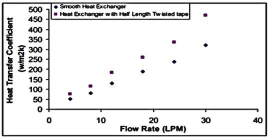
According to Yadav [28], who experimentally evaluated the effects of obstacles in a heat exchanger, heat transfer performance was maximized by adding obstacles compared to a conventional smooth pipe, with its transfer coefficient increasing by 40%, as shown in Figure 4:
Figure 4. Heat transfer coefficient as a function, adopted from [28]
Afshari et al. [29] studied the impacts of the addition of obstacles on the thermal performance of a solar heater through experimental tests and simulations, obtaining similar results, in which the obstacles provide a more homogeneous temperature distribution due to an increase in energy gain, as seen in Figure 5, which also highlights greater effectiveness of the method by adding a second row of obstacles. The study evaluates that the presence of obstacles improved the thermal performance since the maximum instantaneous efficiency of the heater reached 71.41% experimentally.
Darbandi and Ghafourizadeh [19] found similar results by simulating a combustion chamber with turbulence intensities of 3%, 10%, 15%, and 20% and aviation kerosene as fuel. This study also found an improvement in thermal behavior, achieving temperatures from both inside the chamber and increasing exhaust gases as turbulence intensifies. In addition, the flame structure was also improved, as more intense turbulence produced a shorter flame, essential for an aerospace equipment engine. Such improvements are attributed by the authors to improvements in the mixing rates of fuel with oxidant, resulting in a more optimal combustion reaction from the increase in turbulence intensity.
Figure 5. Temperature variation within the heater pipes, adopted from [29]
4.2 Obstacles in cooling channels
For the proper operation of the rocket engines using a liquid propellant, it is essential to apply refrigeration techniques in the combustion chamber since, because of them, the engine does not have excessive wear, increasing its service life and reliability of the rocket nozzle. Although the temperature is an important factor, several other variables are needed in a design for cooling a nozzle. A good design should also minimize fuel load losses, wall thicknesses, and engine mass, limit fuel heating avoiding degradation and vaporization, and be manufactured and possess adequate structural strength.
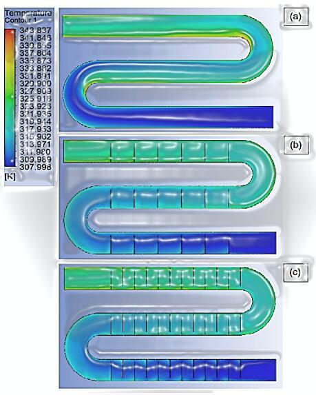
The feasibility of using obstacles in a cooling channel was investigated to reduce the maximum temperature of the hot gas wall. The addition of obstacles in the initial configuration showed that heat transfer could be increased with a subsequent pressure drop [20]. The study, with several configurations, showed the characteristics of thermal performance in the cooling channel (Figures 6 and 7).
Figure 6. Channel background wall in the middle plane, adopted from [20]
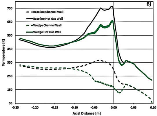
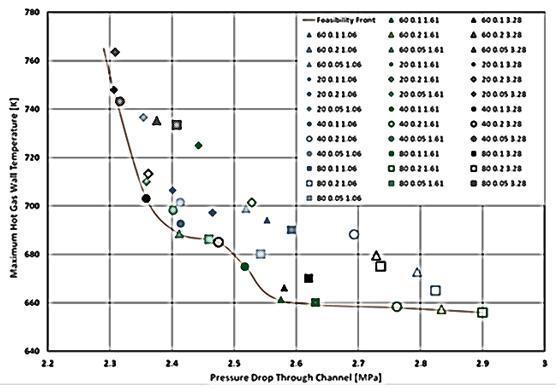
Figure 7. Viability front results with all labeled wedge cases, adopted from [20]
In Figure 6, it is possible to observe the analysis of temperature and pressure on the hot gas walls and the analysis of the sidewalls compared to the baseline condition. It is verified that the maximum temperature of the hot gas wall of the initial wedge case is 661 K. This represents a reduction of 104 K compared to the baseline results. The drop in pressure in the channel of the initial wedge case was 2.58 MPa which is a 12.4% increase in pressure drop on the baseline case. This analysis was made considering wedge-shaped obstacles. Another analysis made in the same way as the previous one, but with the Obstacles in V format, it was obtained as a result that the maximum temperature of the hot gas wall of the rib box is 755 K.
This represents a reduction of only 10 K when compared to the results of the baseline. The pressure drop through the rib cage canal was 2.83 MPa, a 23.7% increase in pressure drop. As can be seen, the reduction of the temperature in wedge format was more than ten times higher than that in V format and the increase in pressure is about half of that in the box with the second format mentioned.
It was also concluded that twice as much heat traveled through the sidewall of the canal than through the lower wall of the canal itself. In cases of square obstacles in the rocket nozzle, the flow through the lower wall increased, and the flow through the side walls decreased. This flow behavior is due to obstacles, which increase the heat transfer coefficient (HTC) on the lower wall much more effectively than on the sides. As the maximum temperature of the hot wall decreases, the proportion of the side wall flow to the lower wall flow is also mitigated.
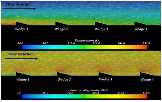
Some settings are more efficient in all geometries considered, increasing the HTC with a slight increase in friction factor. From the general point of view of the channel, square-shaped obstacles do not efficiently mix flow. Figure 8 shows a recirculation zone that exists just below the back edge of the ribs [21]. This effect contributes to the lack of a substantial reduction in the temperature of the hot gas wall due to the lack of mixing.
The triangle-shaped obstacle demonstrates mixing the flow more efficiently than the square and circular geometry. This gain is due to the method by which delta creates vortexes as opposed to squares and circulars, that the mixture near the surface of the hot channel wall (bottom wall) is much larger than the mixture caused by the other geometries. Tyler Buchanan concludes that one potential reason for the effectiveness of early triangular geometry in the channel is how it increases the mixing rate. The best efficiency of using a triangle-shaped obstacle facing back than a square stands out since, as shown in Figures 8 and 9.
Figure 8. Generated integral convolution line long, adopted from [20]
Figure 9. Generated integral convolution line convolution, adopted from [20]
Square geometry directs the flow laterally around it, but also directs the flow directly over it, which increases pressure losses, while triangular geometry facing backwards paralyses the flow laterally, while minimally force the fluid to abruptly change direction, moving completely over the obstacle. This lateral separation of the approaching flow turns into vortexes that rotate widely in the normal direction of the flow, increasing the mixing rate on the characterized surface and maintaining improvements at the time of flow.
The obstacle’s influence on temperature can be evaluated from various perspectives, including for different purposes depending on the desired application. For example, obstacles can be used in both combustion chambers and cooling channels, as detailed above, due to the ability of obstacles to influence temperature distribution in ducts and their extreme values, in addition to significantly improving the heat transfer rate, as is its main function in boilers of the metal-mechanical industry today.
Thus, it is still necessary to evaluate the correlation between flame acceleration and DDT with the adiabatic and isothermal transformations in combustion and detonation processes since ensuring an isentropic transformation is essential for the performance of several possible applications of this technology. In this sense, we found concordant results, which will be deepened in this section, for the benefits of obstacles in several aspects mentioned above, such as improving temperature and heat transfer conditions, a fundamental factor for a lasting functioning of structures capable of performing combustion reactions in an isothermal flow, in addition to improving adiabatic and isothermal transformations.
5.1 Adiabatic and isothermal relationships
An isothermal process is a thermodynamic process in which the temperature of the system remains constant (T=const). Heat transfer inwards or outwards occurs at a slow rate to continuously adjust to the temperature of the reservoir by exchanging heat. In the adiabatic process, there is no such exchange of heat with the environment.
Figure 10 shows the main reaction front as a function of time (Figure 10a) and the propagation speed as a function of position (Figure 10b, 10c and 10d) under adiabatic and isothermic conditions in br=0.33, br=0.5 and br=0.67. In general, heat losses result in a weaker flame acceleration in isothermal cases than in adiabatic cases and a longer DDT occurrence time for br=0.33 and br=0.5 for br=0.67, preventing the occurrence of DDT and attenuating flame acceleration. In addition, for the blocking ratios 0.33 and 0.5, the adiabatic and isothermal conditions have propagation speed and the front reaction oscillations as a function of the distance very close.
Figure 10. Analysis of the differences between adiabatic, adopted from [16]
During flame acceleration, the flame front travels in the clear spaces, the height of these spaces is about 73 mm, 36 mm, and 18 mm of laminar flame thickness to br=0.33, br=0.5, and br=0.67, and approximately half of these spaces near the upper and lower walls in the case evaluated by Xiao and Oran [16]. Heat losses to the channel walls and surfaces can influence flame acceleration and TDD in such conditions.
The intensity of turbulence in the gas flow can be affected by several factors: the geometry of the nozzle through which they will be released or by the positioning, quantity, and shape of obstacles fixed inside. The studies that were further developed, based on experimental trials and simulations, found a significant correlation between the insertion of obstacles, the variation of nozzle geometry, and the formation of turbulent flow.
For combustion and detonation processes, a turbulent flow can enable favorable conditions for an increase in the acceleration of flame and exhaust gases, and consequently their speed, as well as provide ideal pressure conditions in pipes with the isothermal flow and the improvement of TDD.
6.1 Flow
Considering that the obstacles provide a disturbance to the isothermal flow of fluids, it is expected that there will be an increase in turbulence in the flow of the fluid, which can cause improvements in other aspects of the flow that will be detailed later. In this sense, Seo et al. [30] compared experimental data with two turbulence models, κ − ε and κ − ω, based on RANS equations and with a multifractal to predict the evolution of turbulence in an asymmetric jet nozzle, finding greater precision through multifractal, as both other models fail to predict the decline of turbulence along with the nozzle.
Different measurements were varied for the nozzle, and it was found that the shape of the round and longer nozzle output caused a turbulence intensity better distributed in the flow and more stable, concentrating the turbulence in the center by a greater longitudinal extension due to the maximum increase of approximately 5.1% in the exponent of Lipschitz - Hölder (αmin), analytical methods to relate turbulence models to nozzle characteristics. From numerical simulations, Yakut et al. also obtained results that indicate an increase in turbulence to low Reynolds numbers (< 12000) with the addition of obstacles in a heat exchanger, which formed small-amplitude vortexes, generating flow-induced vibrations.
These observations added to those found in Ref. [23], in which Kumar and Sahu [23] experimentally studied the impact of the geometry of coaxial injectors of jet fluids, widely used in rocket engines to mix fuel with oxidants, in other important factors of the process, such as the average length of jet separation (mean jet breakup length) and primary jet instabilities, attributed to the separation of airflow highlight considerations to be analyzed in the possibility of using injectors as obstacles in order to generate turbulence. Thus, in the analysis of Zhao et al. [17], the insertion of jets in a detonation tube led, both in the air-only jets, and in those that expelled a mixture of air with kerosene, to periodic vortexes in the flow, causing turbulence within the detonation tube, and the mixture jets obtained a higher intensity of turbulence.
Another research that evaluates the turbulence of the flow, although briefly, uses CFD simulations and experimental tests of the insertion of obstacles in the exit section of a convergent-divergent nozzle. Kostić et al. [27] found a distribution of turbulence intensity through the nozzle, having a more turbulent flow soon after passing the obstacle, with the highest intensities concentrated at the edges of the nozzle, as illustrated in Figure 11. After passing through the obstacle, the number of Mach of the flow declined approximately 15% compared with the obstacle-free flow.
However, both presented the same Mach number at the exit, indicating a faster increase of this value in the nozzle with the presence of obstacles. Also, the authors state that it is necessary to analyze more obstacle formats to calibrate the method to obtain conclusive results since only one hypothesis was considered.
Figure 11. Turbulence intensity calculated, adopted from [27]
6.2 Pressure
The total pressure affects the combustion and explosion process, mainly in isentropic flows, since it is the difference in pressure at the outlet of the duct with the external pressure that will allow the effective exhaust of gases. Li et al. [31] observed that it is possible to model and predict the variation of pressures in an explosion with obstacles and their subsequent structural damage. From the comparison of 3 different methods, it was inferred that the predictions of the correlations of CSC and software FLACS (CFD) showed greater agreement with each other and also that it is essential to use precise methods because the explosion with obstacles can generate permanent structural damage to the devices.
Nevertheless, the analysis was held to an industrial explosion with generalized obstacles, with different types of gas, such as pure methane and propane, i.e., it did not deepen the effects and forecast of the pressure itself. Kostić et al. [27] addressed the particularities of inserting obstacles into a convergent-divergent nozzle with the supersonic flow. The study mainly dealt with validating the CFD model for the nozzle and 2D obstacles, which obtained results in agreement with those found experimentally. It was possible to find values for several flow parameters, including static, dynamic, and total pressures along the longitudinal length of the nozzle.
The values with and without obstacles were similar in much of the length, except for the moment when the turbulence generated an oblique shock in the exit section, where the obstacles were located, in which there was a small jump of 40 mbar in static pressure, which resolved by 40 mm and reached the same value as the unobstructed nozzle (Figure 12) and a reduction of 80 mbar or 8% in total pressure, as shown in Figure 13. In addition, Figure 14 shows the disturbance in dynamic pressure caused by obstacles responsible for the decay at total pressure.
Therefore, it is highlighted the extreme importance of using precise methods for pressure prediction and analysis since it interferes both in the performance of pipelines with the isothermal flow and in the durability of the structure. This is said, it is possible to infer that the presence of turbulence, which can be produced by obstacles as previously addressed, can provide ideal pressure conditions in various situations.
When testing the presence of obstacles in a detonation tube, with an emphasis on the impact of the turbulence generated by the jets on the pressure waves, it was possible observed that the distance between the pressure waves and flame propagation waves was reduced and, more importantly, the pressure value at its peak increased to the turbulence of the jet with a mixture of kerosene and air, compared to those of the pure air jet or even without a turbulence agent, cases with despicable divergences and where the speed of the flame propagation wave was lower than that of the pressure wave, preventing pressure and velocity waves from finding themselves in ideal situations in the output section of the pipe, which makes the detonation process in the tube [17].
Figure 12. Adapted from Estatic pressure, adopted from [27]
Figure 13. Local pressure, in mbar units, adopted from [27]
Figure 14. Dynamic pressure, in mbar units, adopted from [27]
6.3 Acceleration and velocity
The use of obstacles is mainly in the metal-mechanical industry, focused on pressure and temperature conditions and heat transfer. Because of this, there are few studies and analyses, both numerical and experimental, in addition to the impact of the use of obstacles on the acceleration and speed of exhaust gases.
Zhao et al. [17] used a disturbance of an air jet to generate turbulence in a subsonic combustion detonation tube. It was observed that a mixture of air and kerosene led to a higher intensity of turbulence and acceleration of the flame along the tube, with the speed of flame propagation at the outlet in the tube with mixing jets being 144 m/s or 12% higher than the tube with fresh air jet and 533 m/s or 44% higher than that without any jet, approximately, as shown in Figure 15. The authors observed in the combustion reaction under subsonic conditions that the speed of flame propagation waves should be higher than pressure waves to ensure a beneficial procedure for the use of turbulent flow.
The difference between the waves using a jet of clean air for those with no turbulence was derisory, so this, tied with a complication in the distribution of fuel generated by the use of pure air jets, showed that it is disadvantageous use this method of generating turbulence. On the other hand, the velocity of the flame of the jet of the mixture of air with kerosene was much higher than that of the no turbulence or with the jet of clean air due to the speed of the flame wave being significantly higher than that of the pressure wave. Therefore, this mixing jet proved effective in accelerating the flame velocity, adding to the production of better detonation conditions in the tube.
Figure 15. Wave propagation velocity, adopted from [17]
The acceleration of the flame formed by a mixture of air and hydrogen passing through a channel is notably affected by the obstacles inserted, as explained by Xiao and Oran [16], who also cite the question of speed for the occurrence of Deflagration Transition to Detonation (TDD). Three hypotheses were tested: blocking ratio, adiabatic and isothermal relationship, and different geometries as obstacles, which could or could not cause DDT more quickly, as previously mentioned. It is important to highlight that, usually, the ignition initiates a deflagration. It transitions to a detonation, generating a TDD process associated with a turbulence-generating obstacle. In general, the very early acceleration of a laminar flame in channel results mainly from the thermal expansion of hot combustion products.
The obstacles allowed the formation of vortexes that, when interacting with the flame, considerably increase the surface area of the flame because, as the flame passes through the obstacles, it is elongated in the unobstructed directions, it is dragged and twisted on obstacle tracks as it travels through the spaces between neighboring obstacles, leading to the increased surface area of the flame and accelerates the flow. The accelerating flow produces perceptible vortexes that detach from the lower and upper sides of the obstacles. Disturbances in the mats cause fragmentation of the flame and, consequently, rapid growth in the surface area of the flame. In addition, there was the formation of shock waves and compression waves, increasing the firing speed and density of the pre-combustion mixture, which increased the rate of heat release, causing instabilities in the flame, which caused more shock waves [16].
The authors considered hypotheses that can alter the acceleration of the flame and, consequently, the detonation. While the different geometries of obstacles and adiabatic and isothermal relationships have been addressed before, the blocking ratio (br), i.e., the ratio between the sum of the height of the tube and the heights of the obstacles in the vertical direction, can considerably affect the DDT. Thus, the differences in the process were observed between three values: br=0.33, br=0.5 and br=0.67. The lock ratio br=0.33 is related to the highest values for time and distance for the deflagration transition to detonation, while br=0.5 with the shortest distance and br = 0.67 with the shortest time for TDD, as can be seen in Table 1:
Table 1. Time and distance for the transition from deflagration to detonation at different values of blocking ratio
|
Lock ratio (br) |
Time for TDD |
Distance for TDD |
|
0.33 |
2.82 ms |
53.7 cm |
|
0.5 |
2.23 ms |
35.1 cm |
|
0.67 |
1.74 ms |
42 cm |
It is understood that the detonation failure is more significant as the blocking ratio increases, as can be seen in Figure 16. At the blocking ratio of 0.67 it can be observed that there is a moment - between 18.9 cm to 39.1 cm - in which there is a propagation phase, during which the average velocity is about 800 m/s, around 40% of the detonation speed (1993 m/s). This regime is typical of the supersonic combustion wave spread asphyxia regime [32]. This regime is much less noticeable in br=0.5 and br=0.33, in which no asphyxia regime appears to occur throughout the course.
Figure 16. Relationship between, adopted from [16]
In this way, it is possible to induce that the induction of a turbulent flow through obstacles can provoke a significant turbulent flow that, for combustion and detonation processes in an isothermal flow duct, which presented benefits in the speed and acceleration of the flame by generating favorable conditions for the increase of these in the propagation of flame and exhaust gases. This demonstrates the need to study and test this application more deeply, as it can be applied in other industries in a potentially beneficial way.
Darbandi and Ghafourizadeh [19] evaluated the emission of pollutants and soot formation due to obstacles inserted in a combustion chamber using aviation kerosene as fuel. A 14% decrease in the emission of nano soot particles in aerosol was observed as the turbulence intensity (TI) increased from 3% to 20%, as well as the diameter of these particles (Figure 17).
Figure 17. Production of nano soot particles, adopted from [19]
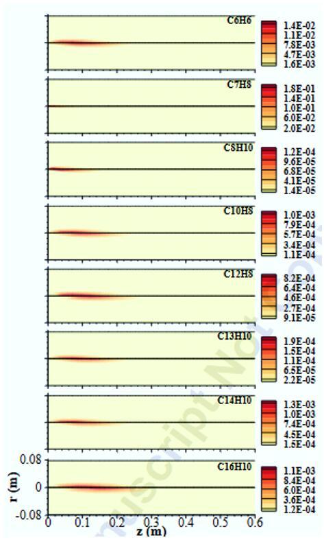
There was also a significant reduction in the emission of pollutant by-products benzene (C6H6), toluene (C7H8), xylene (C8H10), naphthalene (C10H8), Acenaftilene (C12H8), fluorene (C13H10), fenanthen (C14H10) and pyrene (C16H10), aromatic compounds resulting from the incomplete combustion reaction of the fuel used, as shown in Table 2. In Figure 18, it is notable that the production of the pollutants mentioned above within the combustion chamber for the two turbulence hypotheses mentioned, but it is not possible to infer how significant the difference between them is due to the scale considered by the authors.
Table 2. Percentage difference in the emission of the pollutants mentioned. Byproducts Difference (%) between the fractions of emitted mass with TI=3% and TI=20%
|
C6H6 |
−94.78% |
|
C7H8 |
−95.00% |
|
C8H10 |
−96.35% |
|
C10H8 |
−96.07% |
|
C12H8 |
−96.68% |
|
C13H10 |
−98.46% |
|
C14H10 |
−97.30% |
|
C16H10 |
−95.49% |
As the more turbulent flow allows a more efficient mixture of fuel with the oxidizer, combustion occurs faster and more efficiently, forming fewer by-products. Since the abovementioned compounds represent the majority of the air pollution generated by the combustion of aviation kerosene, it is concluded that the insertion of turbulence-generating obstacles can become a form of significant attenuation in the emission of pollutants.
Thus, the motivation arises to analyze this application of obstacles in other industries from more experiments or simulations dealing with the optimization of this combustion reaction.
However, there is still insufficient evidence of other progress made possible by obstacles in the emission of pollutants in other situations and industries, such as better efficiency of the combustion chamber, which could provide greater use of fuel with oxidant, allowing to use less fuel, which, in addition to polluting less, would allow occupying a smaller part of the payload with propellant.
Figure 18. Production of the pollutants mentioned, adopted from [19]
The nozzles in the aerospace industry used in rocket engines are conventionally convergent-divergent and have the purpose of propelling exhaust gases. Thus, although the work is focused on the study of obstacles in an isothermal flow duct, the study of nozzle geometry is essential to improve the performance in the exhaust chamber along with the obstacles.
The optimization of its geometry is essential to achieve the best pressure and temperature conditions of the obstructed flow, consequently increasing the speed of gases at the nozzle outlet [33], as well as improving the mixing rate of the fuel with the oxidant due to an increase in fluid compressibility, i.e., for high numbers of Mach32, which helps in the stability and structure of the flame formed [34]. In this sense, the flow rate increases as fluid enters the nozzle through the convergent section in subsonic flow until it reaches the throat, where it becomes sonic. Throughout the divergent section, the flow continues to accelerate until it reaches supersonic conditions at the outlet if it presents sufficient pressure and temperature conditions since there is an increase in kinetic energy due to the fall of enthalpy due to the expansion of the gas.
As a result, the performance of a nozzle is quantified from the critical downstream pressure ratio by the upstream (Pd/Pu) and the pressure drop along with the nozzle. A nozzle geometry with good performance achieves the strangulation with a greater critical pressure ratio due to the pressure recovery when the fluid passes through the throat and flows through the divergent section, minimizing the pressure drop [35]. Thus, it is essential to use better performance geometry for the insertion of obstacles in order to achieve the best possible rocket engine performance optimization.
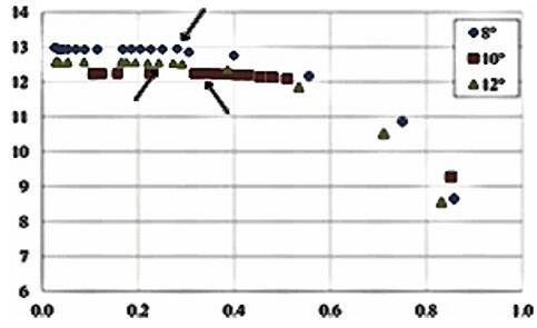
Seeking to understand which aspect of the geometries led to the best performance, pressure readings were recorded at different locations of the nozzle, analyzing the angle of divergence and convergence, neck length, and parabolic and convergent geometries, which did not significantly interfere with the performance 6 [32, 36]. Since the flow is still subsonic in the convergent region of the nozzle, the variation of its angle did not influence performance as the angle of divergence [32]. Thus, nozzles were tested with angles of 8°, 10°, and 12° of divergence, resulting in a lower performance from the increase of this angle, as shown in Figure 19.
Figure 19. Nozzle data, adopted from [32]
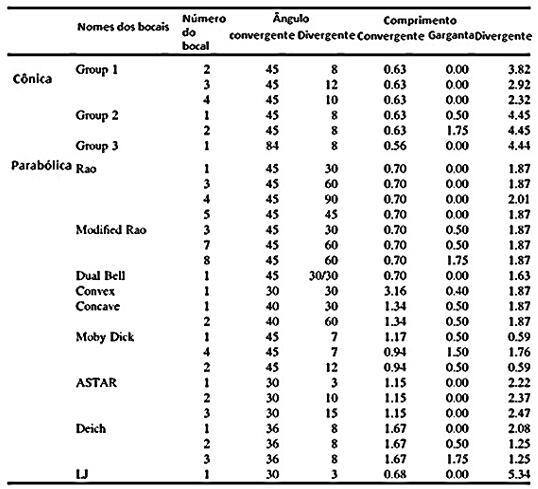
Singh et al. analyzed the effects of various geometric parameters, such as shape and angle of convergent and divergent sections and neck length, based on experimental tests with 3D printed miniatures until it is found one that maximizes the critical pressure ratio and improves pressure drop over the nozzle.
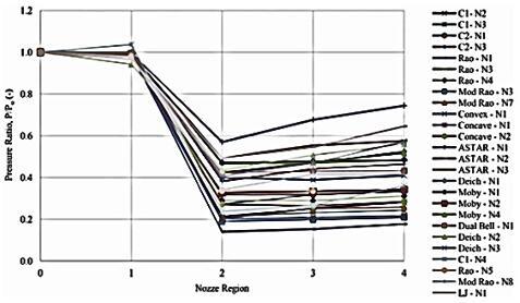
Figure 20. Nozzle performance, adopted from [32]
Downstream and upstream pressures were measured to identify the transition between the critical and subcritical flow from the tests. Using these values, the ratio between upstream and downstream pressures was calculated, as well as the pressure drop along with the nozzle, elaborating a graph with the results of each nozzle (Figure 20), in which it was observed that the nozzles with high critical pressure rate also presented a lower critical pressure drop, with emphasis on the good performance of geometric configurations ASTAR, Deich, Moby Dick and LJ.
Figure 21. Analysis of the divergence angle, adopted from [32]
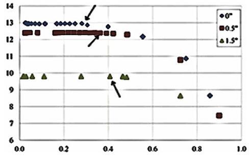
When evaluating the effect of three throat lengths, 0, 0.5, and 1.5 inches, with the same angle of divergence, it is inferable that a more elongated throat has a higher critical pressure ratio (Figure 21). However, since the tests were performed on miniature nozzles, the air velocity was lower than in full, since this increases in nozzles with larger length and area, therefore, the friction pressure in the fall is higher, resulting in a greater pressure drop throughout the nozzle, a more elongated throat negatively impacts the performance of the mouthpiece [32], as shown in Figure 22.
Figure 22. Analysis of the throat length, adopted from [32]
It is concluded, from these analyses, that the geometry of the nozzle is of paramount importance for performance, highlighting that the length of the nozzle and its angle of convergence do not affect the nozzle performance, while a smaller angle of divergence and a shorter throat provide the best ratio of critical pressure and pressure drop. Thus, the ASTAR 1 nozzle presented better results since it has a divergent parabolic section with an angle of 3º without an elongated throat.
However, the LJ nozzle also presented good results and with these data may have the possibility with future studies on the theme of increased performance, which is the final result, based on the adjustments of the flow, pressure, temperature, speed, both products due to the adaptation of the nozzle geometry, which can be further influenced, and enhanced, by the use of obstacles. When evaluating nozzles with similar geometries with the same CFD model, it reached concordant conclusions, ascertaining the fidelity and reproducibility of the method [37, 38].
It is clear from this review that the field of study of the insertion of obstacles in flows to generate turbulence to improve the energy efficiency of flow equipment is very vast and impacts several performance factors of such equipment.
It should be noted that the addition of obstacles in the medium leads to the formation of turbulence in the flow of fluids, implying a higher rate of a fuel mixture when applied in combustion chambers, an increase in the rate of heat transfer when applied to heat exchangers, or an increase in TDD acceleration. There are also indications that obstacles lead to a reduction in the formation of toxic and pollutant by-products from combustion.
The quantitative changes resulting from the application of obstacles in these flow machines open opportunities for new arrangements, such as the possibility of using new fluids or a new combination of construction materials.
[1] Han, J.C., Park, J.S., Lei, C.K. (1985). Heat transfer enhancement in channels with turbulence promoters. Journal of Engineering for Gas Turbines and Power, 107: 628-635. https://doi.org/10.1115/1.3239782
[2] Mahmood, G.I., Hill, M.L., Nelson, D.L., Ligrani, P.M., Moon, H.K., Glezer, B. (2000). Local heat transfer and flow structure on and above a dimpled surface in a channel. Journal of Turbomachinery, 123: 115-123. https://doi.org/10.1115/1.1333694
[3] Mahmood, G.I., Ligrani, P.M. (2002). Heat transfer in a dimpled channel: Combined influences of aspect ratio, temperature ratio, Reynolds number, and flow structure. International Journal of Heat and Mass Transfer, 45: 2011-2020. https://doi.org/10.1016/S0017-9310(01)00314-3
[4] Dixit, A., Patil, A.K. (2015). Heat transfer characteristics of grooved fin under forced convection. Heat Transfer Engineering, 36: 1409-1416. https://doi.org/10.1080/01457632.2015.1003726
[5] Maschmann, M., Ma, H. (2006). An investigation of capillary flow effect on condensation heat transfer on a grooved plate. Heat Transfer Engineering, 27: 22-31. https://doi.org/10.1080/01457630500454939
[6] Olsson, C.O., Sunden, B. (1998). Thermal and hydraulic performance of a rectangular duct with multiple V-shaped ribs. Journal of Heat Transfer, 120: 1072-1077. https://doi.org/10.1115/1.2825892
[7] Promvonge, P., Chompookham, T., Kwankaomeng, S., Thianpong, C. (2010). Enhanced heat transfer in a triangular ribbed channel with longitudinal vortex generators. Energy Conversion and Management, 51: 1242-1249. https://doi.org/10.1016/j.enconman.2009.12.035
[8] Yakut, K., Sahin, B. (2004). Flow-induced vibration analysis of conical rings used for heat transfer enhancement in heat exchangers. Applied Energy, 78: 273-288. https://doi.org/10.1016/j.apenergy.2003.09.001
[9] Anvari, A.R., Lotfi, R., Rashidi, A.M., Sattari, S. (2011). Experimental research on heat transfer of water in tubes with conical ring inserts in transient regime. International Communications in Heat and Mass Transfer, 38: 668-671. https://doi.org/10.1016/j.icheatmasstransfer.2011.03.016
[10] Promvonge, P., Eiamsa-ard, S. (2007). Heat transfer behaviors in a tube with combined conical-ring and twisted-tape insert. International Communications in Heat and Mass Transfer, 34: 849-859. https://doi.org/10.1016/j.icheatmasstransfer.2007.03.019
[11] Bhattacharyya, S., Benim, A.C., Chattopadhyay, H., Banerjee, A. (2019). Experimental and numerical analysis of forced convection in a twisted tube. Thermal Science, 23: S1043-S1052. https://doi.org/10.2298/TSCI19S4043B
[12] Kapse, A., Dongarwar, P., Gawande, R. (2016). Thermohydraulic performance comparison of compound inserts for a turbulent flow through a circular tube. Thermal Science, 21: 96-96. https://doi.org/10.2298/TSCI151027096K
[13] Lotfi, B., Sundén, B. (2020). Thermo-hydraulic performance enhancement of finned elliptical tube heat exchangers by utilizing innovative dimple turbulators. Heat Transfer Engineering, 41: 1117-1142. https://doi.org/10.1080/01457632.2019.1611132
[14] Ventola, L., Fasano, M., Cappabianca, R., Bergamasco, L., Clerici, F., Scaltrito, L., Chiavazzo, E., Asinari, P. (2020). Convective heat transfer enhancement through laser-etched heat sinks: Elliptic scale-roughened and cones patterns. Energies, 13: 1360. https://doi.org/10.3390/en13061360
[15] Elyyan, M.A., Rozati, A., Tafti, D.K. (2008). Investigation of dimpled fins for heat transfer enhancement in compact heat exchangers. International Journal of Heat and Mass Transfer, 51: 2950-2966. https://doi.org/10.1016/j.ijheatmasstransfer.2007.09.013
[16] Xiao, H., Oran, E.S. (2020). Flame acceleration and deflagration-to-detonation transition in hydrogen-air mixture in a channel with an array of obstacles of different shapes. Combustion and Flame, 220: 378-393. https://doi.org/10.1016/j.combustflame.2020.07.013
[17] Zhao, S., Fan, Y., Lv, H., Jia, B. (2017). Effects of a jet turbulator upon flame acceleration in a detonation tube. Applied Thermal Engineering, 115: 33-40. https://doi.org/10.1016/j.applthermaleng.2016.12.068
[18] Barcelos, B., Centeno, F. (2019). Numerical assessment of the effect of inflow turbulators on the thermal behavior of a combustion chamber. Thermal Science, 25: 323-323. https://doi.org/10.2298/TSCI181119323B
[19] Darbandi, M., Ghafourizadeh, M. (2017). Numerical study of inlet turbulators effect on the thermal characteristics of a jet propulsion-fueled combustor and its hazardous pollutants emission. Journal of Heat Transfer, 139(6): 061201. https://doi.org/10.1115/1.4035443
[20] Buchanan, T. (2018). Investigation into the feasibility of adding turbulators to rocket combustion chamber cooling channels using a conjugate heat transfer analysis. Electronic Theses and Dissertations. 6007. https://stars.library.ucf.edu/etd/6007, accessed on 16 August, 2020.
[21] Lakshminarayana, B. (1995). Fluid Dynamics and Heat Transfer of Turbomachinery. John Wiley & Sons. https://doi.org/10.1002/9780470172629
[22] de Oliveira, F.S. (2013). Study of materials for the manufacture of hybrid propellant rocket nozzle. https://repositorio.unb.br/handle/10482/14083. accessed on 16 August, 2020.
[23] Kumar, A., Sahu, S. (2020). Influence of nozzle geometry on primary and large-scale instabilities in coaxial injectors. Chemical Engineering Science, 221: 115694. https://doi.org/10.1016/j.ces.2020.115694
[24] Taslim, M.E., Spring, S.D. (1994). Effects of turbulator profile and spacing on heat transfer and friction in a channel. Journal of Thermophysics and Heat Transfer, 8: 555-562. https://doi.org/10.2514/3.578
[25] Kim, K.M., Lee, H., Kim, B.S., Shin, S., Lee, D.H., Cho, H.H. (2009). Optimal design of angled rib turbulators in a cooling channel. Heat Mass Transfer, 45: 1617-1625. https://doi.org/10.1007/s00231-009-0536-3
[26] Pinos, T., Ciccarelli, G. (2015). Combustion wave propagation through a bank of cross-flow cylinders. Combustion and Flame, 162: 3254-3262. https://doi.org/10.1016/j.combustflame.2015.05.013
[27] Kostic, O., Stefanovic, Z., Kostic, I. (2015). CFD modeling of supersonic airflow generated by 2D nozzle with and without an obstacle at the exit section. FME Transaction, 43: 107-113. https://doi.org/10.5937/fmet1502107k
[28] Yadav, A. (2009). Effect of half length twisted-tape turbulators on heat transfer and pressure drop characteristics inside a double pipe U-bend heat exchanger. Jordan Journal of Mech. and Industrial Engg, 3(1): 17-22.
[29] Afshari, F., Sözen, A., Khanlari, A., Tuncer, A.D., Şirin, C. (2020). Effect of turbulator modifications on the thermal performance of cost-effective alternative solar air heater. Renewable Energy, 158: 297-310. https://doi.org/10.1016/j.renene.2020.05.148
[30] Seo, Y., Ko, H.S., Son, S. (2020). The effect of nozzle geometry on the turbulence evolution in an axisymmetric jet flow: A focus on fractals. Physica A: Statistical Mechanics and Its Applications, 550. https://doi.org/10.1016/j.physa.2020.124145
[31] Li, J., Ma, G., Abdel-jawad, M., Hao, H. (2014). Evaluation of Gas Explosion Overpressures at Configurations with Irregularly Arranged Obstacles. Journal of Performance of Constructed Facilities, 29. https://doi.org/10.1061/(ASCE)CF.1943-5509.0000678
[32] Lee, J.H., Knystautas, R., Chan, C.K. (1985). Turbulent flame propagation in obstacle-filled tubes. Symposium (International) on Combustion, Twentieth Symposium (International) on Combustion, 20: 1663-1672. https://doi.org/10.1016/S0082-0784(85)80662-7
[33] Singh, J., Zerpa, L., Partington, B., Gamboa, J. (2019). Effect of nozzle geometry on critical-subcritical flow transitions. Heliyon, 5: e01273. https://doi.org/10.1016/j.heliyon.2019.e01273
[34] Liu, C., Huang, L., Deng, T., Zhou, S., Liu, X., Deng, J., Luo, Z. (2020). On the influence of nozzle geometry on jet diffusion flames under cross-wind. Fuel, 263: 116549. https://doi.org/10.1016/j.fuel.2019.116549
[35] El-mahallawy, F., Abdelhafez, A., Mansour, M.S. (2007). Mixing and nozzle geometry effects on flame structure and stability. Combustion Science and Technology, 179: 249–263. https://doi.org/10.1080/00102200600809324
[36] Elger, D.F., Roberson, J.A., Crowe, C.T. (2019). Engineering Fluid Mechanics. John Wiley & Sons, Limited. https://doi.org/10.1007/978-981-13-0173-5
[37] Park, K.A., Choi, Y.M., Choi, H.M., Cha, T.S., Yoon, B.H. (2001). The evaluation of critical pressure ratios of sonic nozzles at low Reynolds numbers. Flow Measurement and Instrumentation, 12: 37-41. https://doi.org/10.1016/S0955-5986(00)00040-6
[38] Zang, W., Wang, D., Renganathan, A., Zang. H. (2020). Modeling and assessment of two-phase transonic steam flow with condensation through the convergent-divergent nozzle. Nuclear Engineering and Design, 364: 110632. https://doi.org/10.1016/j.nucengdes.2020.110632