Sarah Bouradi* | Karim Negadi | Rabah Araria | Bachir Boumediene | Mostefa Koulali
© 2022 IIETA. This article is published by IIETA and is licensed under the CC BY 4.0 license (http://creativecommons.org/licenses/by/4.0/).
OPEN ACCESS
Electric vehicles (EVs) provide an excellent opportunity for limiting the emission of a variety of environmentally hazardous gases caused by gasoline and diesel-based vehicles. These propelled vehicles require a forward and backward motion as well as a variable speed operation. Hence, the use of a four-quadrant (4-Q) direct current (DC) converter becomes a necessity. This paper aims to analyse the traction system of an electric automobile along with the improvement of energy efficiency. Inserting a bi-directional DC-DC converter between the battery and the four quadrant-DC chopper assembly allows the power flow from the battery to the motor and the other way around during regenerative braking. Therefore, increasing the limited driving range of the EV. This paper also focused on the application of model reference adaptive fuzzy control (MRAFC) in order to adjust the direct current bus voltage and the DC motor speed. The proposed system has been tested on an experimental bench and the results have been analysed.
electric vehicle, four-quadrant chopper, model reference adaptive fuzzy control, bidirectional DC-DC buck-boost converter, PMDC motor
The environmental impact of CO2 emissions has moved to the forefront of public attention and has been one of the driving forces in leading electric vehicles [1]. The battery-powered electric vehicle (EV) has been proposed as a cleaner and emissions-free alternative to combustion engine-based vehicles. Although the latter still have advantages in terms of limited driving range, price and long recharge time (etc.) compared to EVs, the gap is rapidly closing as more funding and research is being dedicated to eradicating the limitations of electric vehicles.
The advent of lithium-ion (Li-ion) batteries and electric propulsion is igniting a revolution in the transportation sector [2]. These batteries are regarded as the leading generation for electric-powered cars. In comparison with other rechargeable batteries, Li-ion batteries are the main era with regard to strength density. Moreover, they are able to supply up to 3.6 Volts, which is three times greater than Ni-Cd or Ni-MH technology. As an advantage over both Ni-Cd and Ni-MH batteries, Li-ion batteries do not mandate deliberate cycling with the aim to amplify their lives, with a self-discharge rate of 1.5 to 2% in step with month. Thinking about their numerous benefits, Li-ion batteries have huge obstacles that restrict their growth, which include steeply-priced costs (forty percent greater than Ni-Cd), overheating, aging, and the need for safety structures to modify voltage and inner pressures [3].
In electric automobiles, a forward and backward direction is needed along with the variable speed possibility. Therefore, the four-quadrant (4-Q) converter is commonly used in direct current (DC) applications by gaining the possibility to adjust the direction of the voltage source by means of control semiconductor controllers. Thus, it is feasible to divide control into many different modes in order to create a forward motoring mode, a forward regenerative braking mode to return energy to the system, a backward motoring mode, and a reverse regenerative braking mode. In addition to moving transparently by altering the duty cycle and providing an effective channel to recover the regenerative braking power [4].
Along with the four-quadrant converter, a bi-directional DC-DC buck-boost converter is used to ensure the energy flow from the battery to the motor and vice versa [5] in case of regenerative braking. The latter has become a hot topic in the last decade [6], since it is considered as one of the interesting solutions to the limited driving range of electric vehicles [7]. The kinetic energy from the wheels might be captured and turned into electrical power accumulated in the battery during braking, considerably increasing the range per charge and improving overall efficiency. Under normal driving conditions, energy moves from the battery to the motor via the transmission gear and then to the driving axle, as in traditional vehicles with a fixed single gear ratio. The electric motor acts as a generator during regenerative braking, while the driving axle acts as a braking axle, performing regenerative braking torque and turning the generator [8]. Permanent magnet direct current (PMDC) motors are commonly used as electrical drives because of their multiple outstanding features such as a high starting torque, ease of control, as well as having a great flexibility and capacity for applications requiring large inertia loads as a result, it is appropriate for a wide range of industrial applications, including battery-powered devices such as wheelchairs and power tools, industrial equipment, railway traction, manufacturing drives, robotic systems, and precision servos, conveyor belts and gate openers, soldering equipment, X-ray and radiographic systems, and pumping hardware [9]. In recent years, many control methods have been applied to these motors to improve their performance, among these control techniques is the model reference adaptive control (MRAC). This control method was adopted along with the fuzzy logic controller (FLC) in this work, being evolved as a tool for dealing with uncertain, inaccurate, or qualitative decision problems [10] and has been widely exploited for nonlinear systems, high-order and time-delaying systems [11].
This paper is organized as follows: Section 2 discusses the electric traction system along with the physical modeling of the electric vehicle components. Section 3 is focused on the four-quadrant DC-DC converter. The control strategy used for the PMDC motor is discussed in Section 4. The simulation results of the study are shown in Section 5. Section 6 summarizes the work done in the conclusion.
2.1 Electric vehicleanalysis
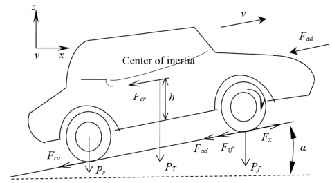
This section describes the driving forces involved in the operation of the vehicle. The elementary forces applied on the electric vehicle are illustrated in Figure 1 [12].
Figure 1. Elementary forces applied to an electric vehicle
The road load is composed of the following forces:
$F_{w}=F_{r o}+F_{s f}+F_{a d d}+F_{c r}$ (1)
The power required to drive a vehicle to balance the road load is given by the following formula:
$P_{v}=v F_{w}$ (2)
The mechanical formula (in the engine coordinate system) used to characterize each wheel drive can be written as:
$J \frac{d \omega_{r}}{d t}+T_{B}+T_{L}=T_{e m}$ (3)
The following equation is derived from the use of a reduction gear.
$\omega_{\text {wheel }}=\frac{\omega_{m}}{G} \omega_{r}, T_{\text {wheel }}=T_{m} G \eta_{t}$ (4)
The load torque in the engine reference system is provided by:
$\omega_{\text {wheel }}=\frac{T_{\text {Lwheel }}}{G} \omega_{r}=\frac{r}{G} F_{\omega}$ (5)
2.2 Description of the system
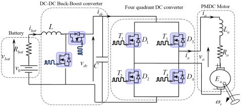
The schematic shown in Figure 2 shows the constituents of the electric vehicle based on an electric drive system. The ultimate purpose of the proposed approach is to control the speed with a model-referenced adaptive fuzzy control using a four-quadrant DC-DC converter.
The constituents of the electric traction system consist of a battery-powered DC voltage source, a bidirectional DC-DC buck-boost converter, a MOSFET-based DC-DC boost converter, a four-quadrant DC-DC converter, and two DC motors located at the back of the electric vehicle and attached to both wheels [13].
Figure 2. The traction system components
2.3 Battery modeling and control
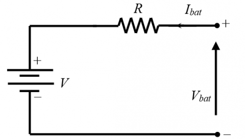
The electrical model of the battery is illustrated in Figure 3 [14, 15].
Figure 3. Battery model
where,
$v_{b a t}=E_{b a t}+R_{b a t} I_{b a t}$ (6)
The battery capacity Cbat can be calculated as follows:
$C_{b a t}=C_{0} \frac{1.67(1+0.005 \Delta T)}{1+0.67\left(\frac{I_{b a t}}{I_{0}}\right)}$ (7)
The state of charge of the battery is given as:
$S O C=1-\frac{Q}{C_{b a t}}$ (8)
where,
$Q=I_{b a t} \times t$ (9)
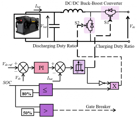
The goal of the control system is to regulate the current of the battery in order to obtain the required power. As seen in Figure 4, the battery is connected to the DC network via a DC-DC bidirectional buck-boost converter. The model has current charge and discharge limits, as well as maximum SOC limits [15].
Figure 4. Battery control scheme
2.4 DC-DC Buck-Boost converter
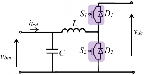
Figure 5 illustrates a buck-boost DC-DC converter that delivers a regulated output voltage that is greater or lower than the source voltage level. Figure 1 demonstrates the converter topology, which includes a DC input voltage source vbat, two controlled switches, a filter inductor (L), a capacitor (C) that works as a filter, and output voltage vdc.
Figure 5. DC-DC Buck-Boost model
When the switch (S1) is turned on for a given time DT, where D is the duty ratio and T is the period, the inductor current iL. flows and the diode gets reverse biased. A voltage is applied across the inductor. This voltage causes the inductor current to increase.
Because of the energy stored in the inductor, the inductor current continues to loop after the switch is switched off. This current goes through the diode, and the voltage across the inductor becomes vL=-vdc for the time (1-D)T it takes to turn the switch back on.
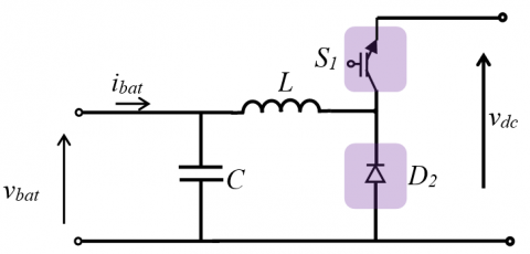
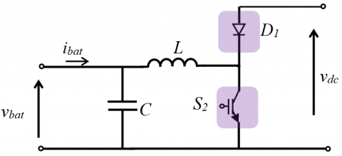
The mathematical modelling of the DC-DC buck-boost converter can be done using the equations obtained from the figures shown in Figure 6, (a) is for the forward mode where the energy flows from the battery to the DC output, and (b) is dedicated to the reverse mode where the energy flows from the DC output back to battery [5, 16].
Introducing u the control output, representing the switch position function, its values vary from 1 when the switch is ON and 0 when the switch is OFF.
(a)
(b)
Figure 6. Buck-Boost model in two transfer directions (a) From vbat to vdc(forward mode), (b) From vdc to vbat (reverse mode)
The state-space model of the buck-boost converter has the following form [17]:
$\frac{d i_{L}}{d t}=(1-u) \frac{v_{C}}{L}+\frac{v_{b a t}}{L} u$ (10)
$\frac{d v_{C}}{d t}=(1-u) \frac{i_{L}}{C}-\frac{v_{C}}{R C}$ (11)
3.1 General description
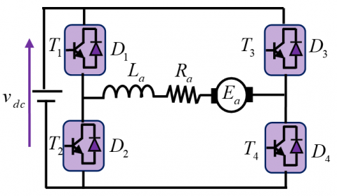
The four-quadrant converter is normally used in DC-DC applications because of its potential to alter the course of the voltage supply primarily based on semiconductor control gadgets. Thus, setting apart in numerous control methods can be achieved. The first approach of control is time ratio control, which is based on the duty cycle variations. This can be obtained by a fixed frequency system or a variable frequency system. The second technique is designed to regulate the current limit. The prior setpoint of inductance current IL determines the ON and OFF state of the chopper circuit in this control approach. When the load hits the higher limit, the chopper turns OFF, and vice versa. Maximum and lowest current levels can be used to set the switching frequency. PWM is a power management technique that is widely utilized for power control in DC-DC converter circuits. The other ways of control depend on the operation of the chopper type. The simplified structure of the 4-Q direct current converter is illustrated in Figure 7 [18].
Figure 7. DC-DC Buck-Boost model
The four-quadrant DC-DC converter topology consists of four semiconductor switches each of which disposes of a reversed biased diode, The DC motor is located in between the four pairs along with its armature resistance Ra and armature inductance La. The switching action of the control pairs leads to the generation of a DC voltage, while the generated current contributes to charging the inductance La; the latter will eventually act as a power source for the circuit [19, 20].
3.2 Operation of the 4-Q DC-DC converter
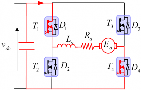
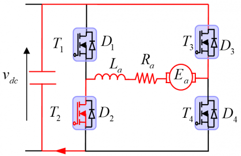
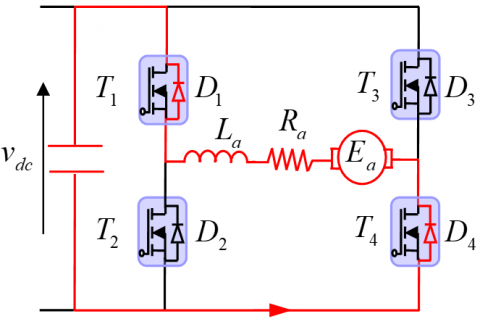
The four-quadrant DC-DC converter, as shown in Figure 8, attempts to harvest a variable DC voltage from a constant DC voltage by adjusting the voltage and current passage in the four-quadrant functions.
(a)
(b)
(c)
(d)
Figure 8. Schematic diagram shows the type of commutation of the switches in all quadrants. (a) First quadrant (b) Second quadrant (c) Third quadrant (d) Fourth quadrant
First quadrant: The motor rotates in the forward direction, the switches T1 and T4 are turned ON, thus the positive voltage from the DC source flows into the DC motor, which leads to a positive torque and a positive speed.
Second quadrant: It is referred to as the forward breaking mode. At the beginning of this mode, only the switch T2 is turned ON, the inductance La takes charge of supplying the circuit with the current. After that T2 is switched OFF and DC voltage turns out to be smaller than that of the generated voltage, which calls for a freewheeling assured by the Diodes D1 and D4. Consequently, the torque is negative while the speed remains positive.
Third quadrant: Usually known as the reverse direction mode, at this stage, the switches T2 and T3 are turned ON, causing the current and voltage flowing to the load to be negative; as a result, the torque and speed become negative, and the polarity of the motor is reversed.
Forth quadrant: It is called the reverse braking mode; similarly to the second quadrant; the switch T4 is the only switch that gets operated in the first half period, the inductance La works as a current source. In the second half period, T4 is turned off, The DC source voltage is actually below the generated voltage, thereby feeding back the induced voltage to the source through the diodes D2 and D3. Therefore, the input voltage flows in negative form, meanwhile, the current is positive. That gives at the end a positive torque and negative speed.
The Table 1 summarizes the operating principle of the 4-Q chopper.
Table 1. 4Q DC-DC converter operating modes
|
State of cells switching |
Direction of current flow |
|
T1, T4 ON T2, T3 OFF D1, D2, D3, D4 OFF |
va>0, ia>0 |
|
T4 ON T1, T2, T3 OFF D1, D4 OFF D2, D3 ON |
va<0, ia>0 |
|
T2, T3 ON T1, T4 OFF D1, D2, D3, D4 OFF |
va>0, ia<0 |
|
T1, T2, T3, T4 OFF D1, D4 ON D2, D3 OFF |
va<0, ia<0 |
4.1 PMDC motor modeling
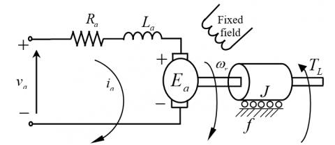
The PMDC is among the most extensively utilized in DC motors because of the ability to separate the motor field and the winding field, both being fed by an additional DC source. Furthermore, regulating the motor speed by adjusting the armature voltage is more feasible. Figure 9 depicts the PMDC schematic model [21].
Figure 9. PMDC motor model
The mathematical model is listed in the following equations [22]:
$v_{a}(t)=R_{a} i_{a}(t)+L_{a} \frac{d i_{a}(t)}{d t}+E_{a}(t)$ (12)
$T(t)=J \frac{d \omega_{r}(t)}{d t}+f \omega_{r}(t)+T_{L}(t)$ (13)
$T(t)=K_{T} i_{a}(t)$ (14)
where, Ra is the armature resistance, La is the winding leakage inductance, ia is the armature current, Ea is the buck electromotive force voltage, KT is the Torque gain, ωr [rpm] is the rotational velocity of the armature and va[V] is the voltage source.
By reconstructing the Eqns. (12) and (13), we obtain:
$\frac{d i_{a}(t)}{d t}=-\frac{R_{a}}{L_{a}} i_{a}(t)-\frac{K_{m}}{L_{a}} \omega_{r}(t)+\frac{1}{L_{a}} u_{a}(t)$ (15)
$\frac{d \omega_{0}(t)}{d t}=\frac{K_{T}}{J} i_{a}(t)-\frac{f}{J} \omega_{r}(t)-\frac{T_{L}(t)}{J}$ (16)
where, J is the inertia of the rotor and the equivalent mechanical load, f [N.m.rad/s] is the viscous friction coefficient, T [N.m] is the electromagnetic torque and TL [N.m] is the load torque.
The following equation represents the state-space model of the motor by choosing x1=ia and x2=ωr:
$\frac{d}{d t}\left[\begin{array}{l}i_{a} \\ \omega_{0}\end{array}\right]=\left[\begin{array}{cc}\frac{-R_{a}}{L_{a}} & \frac{-K_{m}}{L_{a}} \\ \frac{K_{T}}{J} & \frac{-f}{J}\end{array}\right]\left[\begin{array}{l}i_{a} \\ \omega_{0}\end{array}\right]+\left[\begin{array}{cc}\frac{K_{c}}{L_{a}} & 0 \\ 0 & \frac{-1}{J}\end{array}\right]\left[\begin{array}{c}v_{a} \\ T_{L}\end{array}\right]$ (17)
where, Km and Kc are the velocity constant determined by the flux density of the permanent magnet and the converter gain respectively.
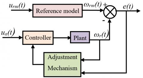
4.2 Model reference adaptive controller (MRAC)
Reference model Adaptive control is one of several strategies used in nonlinear systems and in highly changing processes [23] to produce a suitable behavior of the examined model. The adaptive controller parameters are calculated using the following equation [22]:
$\omega_{r}=\omega_{0}+d_{1}+d_{u}=\omega_{0}+d$ (18)
where, ωr is the output speed of the system with disturbance, ω0 is the plant output speed without disturbance, d1 and duare the effect of load torque on output speed and the effect of uncertainties on output speed, respectively.
From Eq. (17), the velocity of a separately excited DC motor with a neglected load torque and perturbations due to uncertainties is given as follows:
$\frac{d \omega_{0}(t)}{d t}=\dot{\omega}_{0}(t)=-\frac{f}{J} \omega_{0}(t)+\frac{K_{T}}{J} i_{a}(t)$ (19)
The following equation represents the DC-DC converter fed PMDC motor input control:
$\frac{d i_{a}(t)}{d t}=-\frac{R_{a}}{L_{a}} i_{a}(t)-\frac{K_{m}}{L_{a}} \omega_{r}(t)+\frac{K_{c} u_{a}}{L_{a}}$ (20)
where, Kc is the converter gain and ua is the controller input.
The transfer function of the plant without load torque TL=0 considering the uncertainties (ua≠0, d1=0, d=0) is obtained as follows:
$T F=\frac{\omega_{0}}{u_{a}}=\frac{K}{S^{2}+a_{1} S+a_{0}}$ (21)
where, K are calculated as follows:
$\left\{\begin{array}{l}a_{1}=\frac{f}{J}+\frac{R_{a}}{L_{a}} \\ a_{0}=\frac{J R_{a}+K_{m} K_{T}}{J L_{a}} \\ K=\frac{K_{m} K_{C}}{J L_{a}}\end{array}\right.$ (22)
If the load torque is not negligible TL≠0, the Eq. (22) becomes:
$T F_{1}=\frac{-T_{L}(S)\left(R_{a t}+S L_{a t}\right)}{S^{2}+a_{1} S+a_{0}}$ (23)
where,
$\left\{\begin{array}{l}R_{a t}=\frac{R_{a}}{J L_{a}} \\ L_{a t}=\frac{1}{J}\end{array}\right.$ (24)
Thus the resultant speed is obtained by the following equation:
$\omega_{r}(S)=\frac{u_{a}(S)-T_{L}(S)\left(R_{a t}+S L_{a t}\right)}{S^{2}+a_{1} S+a_{0}}+d_{u}(S)$ (25)
A reference model is selected based on its pole orientation, which determines the overall system's stability. The input of the reference model is the input urm for a particular output ωm, which is the required speed response of the system. The reference model parameters are chosen so that the poles of the transfer function at x1 and x2 are towards the left of the s-plane.
The transfer function TFrm of the reference model is determined as follows:
$T F_{r m}=\frac{\omega_{m}(S)}{u_{r m}}=\frac{K_{r m}}{\left(S+x_{1}\right)\left(S+x_{2}\right)}$ (26)
The discrepancy between the actual plant and the reference model is then represented as the error vector:
$e(t)=x_{m}(t)-x_{p}(t)$ (27)
When the disturbances are absent the error becomes:
$e_{0}(t)=\omega_{0}(t)-\omega_{m}(t)$ (28)
When disturbances are present, the error can be determined using the following equation:
$e_{r}(t)=\omega_{r}(t)-\omega_{m}(t)$ (29)
Thus the Eq. (30) can be written as:
$e_{r}(t)=\omega_{0}(t)+d(t)-\omega_{m}(t)=e_{0}(t)+d(t)$ (30)
Figure 10 shows the scheme of the MRAC applied to the PMDC motor.
Figure 10. MRAC scheme of PMDC motor
In summary, the adaptation process is based on the convergence of the error to zero, which leads to the convergence of the controller output to a constant value. Therefore, the motor speed becomes constant. If there will be any perturbations or variations in torque and load, the adjustment process is resumed until the error between and converges towards zero.
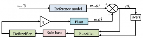
4.3 Model reference fuzzy adaptive controller (MRFAC)
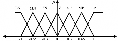
Fuzzy logic control is typically used to generate nonlinear controllers enabling them to perform various complex nonlinear control functions, even for highly uncertain nonlinear systems [24]. In contrast to typical control approaches, an MRFAC technique does not include any accurate modeling of the system, such as the poles and zeros of the system transfer function. To achieve a reasonable rising time, settling time, overshoot, and steady-state error, fuzzy logic is applied. The proposed solution lowers the inaccuracy of the target speed control. This control approach has an advantage over other control systems in that it is insensitive to changes in plant parameters. The specification of membership functions is illustrated in Figure 11 [25].
Fuzzification, fuzzy control rules, and defuzzification are the three steps of FLC. The difference between the error and its fluctuation as input and the difference between the control signal as output. The control signal is created by adding the signal time value from the previous iteration to the output signal of the fuzzy controller. The fuzzy controller rules are shown in Table 2. The function forms are properly chosen. The fuzzy controller rules are shown in Table 2. Figure 12 displays the MRFAC system used on the PMDC motor.
Table 2. Rules of fuzzy controller
|
e(t) |
$\Delta e(t)$ |
||||||
|
LN |
MN |
SN |
Z |
SP |
MP |
LP |
|
|
LN |
LP |
LP |
LP |
MP |
MP |
SP |
Z |
|
MN |
LP |
MP |
MP |
MP |
SP |
Z |
SN |
|
SN |
LP |
MP |
SP |
SP |
Z |
SN |
MN |
|
Z |
MP |
MP |
SP |
Z |
SN |
MN |
MN |
|
SP |
MP |
SP |
Z |
SN |
SN |
MN |
LN |
|
MP |
SP |
Z |
SN |
MN |
MN |
MN |
LN |
|
LP |
Z |
SN |
MN |
MN |
LN |
LN |
LN |
Note: LP: Large Positive; MP: Medium Positive; SP: Small Positive; Z: Zero; SN: Small Negative; MN: Medium Negative; LN: Large Negative.
Figure 11. Specification of a membership function
Figure 12. MRAFC scheme of PMDC motor
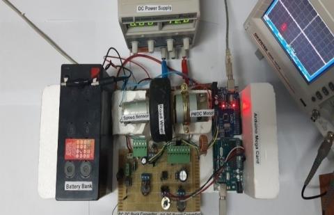
Experiments were carried out under varied load situations on an electric vehicle driven by a permanent magnet direct current motor (PMDC), the engine parameters of which are specified in Table 3 of the appendix, in order to validate the effectiveness and dynamic response of the suggested method. The battery specifications are listed in Table 4, as well as the DC-DC converter parameters, which are presented in Table 5. Figure 13 demonstrates the experimental setup.
Table 3. PMDC parameters
|
Components |
Rated values and reference |
|
Rated power |
68.7 W |
|
Voltage |
14.4V |
|
Rated speed |
5887 rpm |
|
Nominal Current |
1.463 A |
|
Nominal torque |
25.18 Nm |
|
Rotor (Resistance, Inductance) |
Ra=0.8 Ω, La=0.002 H |
|
inertia moment |
J=0.012 kgm²/s² |
|
viscous friction |
F=0.001 N.m.rad/s |
Table 4. Battery parameters
|
Components |
Rating values |
|
Nominal Voltage |
Vbat=12 V |
|
Capacity |
Cn=6 Ah |
Table 5. DC-DC converter parameters
|
Components |
Rating values |
|
Capacitor |
140 µF |
|
Inductance |
L=5.5 mH, r=1.2 Ω |
|
Resistance |
100 Ω |
|
Potentiometer |
10 kΩ |
|
MOSFET |
IRF530N |
|
Diode |
UF 5408 |
Figure 13. Experimental setup for testing the proposed structure of electric vehicle drive
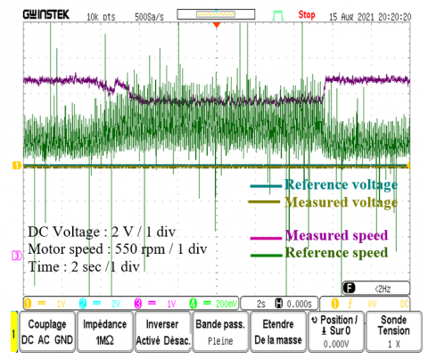
Figures 14-17 show the performance of the motor speed, DC voltage and current obtained without a DC-DC converter. The experimental results confirm that the system loses its stability for a degraded battery voltage and no element of the conversion chain reacted to improve the situation.
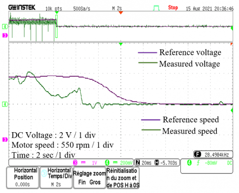
In the case of a decrease in the battery voltage (to 7 Volts) caused by a failure or overconsumption, the dynamic characteristics of Figure 17 below are obtained. Operation at low speed causes the presence of a considerable transient peak with better compliance with the order of the control in the steady-state. On the other hand, in the event of a high speed caused by the control, there is a very large static error due to the limitation of the maximum electrical power generated by the battery.
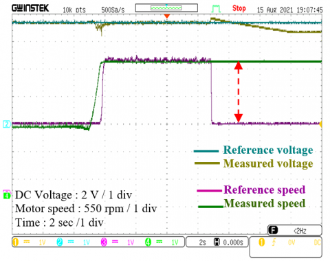
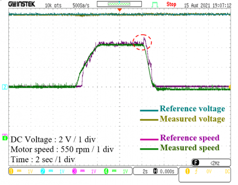
Figure 18 indicates the experimental outcome of a free acceleration speed utilizing the reference model adaptive control. Furthermore, the actual speed is measured and compared. It is apparent that there is a clear correlation between the reference and real speeds, with no steady-state inaccuracy. In the same Figure 18 appears the reference and measured DC voltage evolution, the controlled voltage is not affected by the transient starting regime and the change in the reference speed setpoint, which explains the correct intervention of the control algorithm.
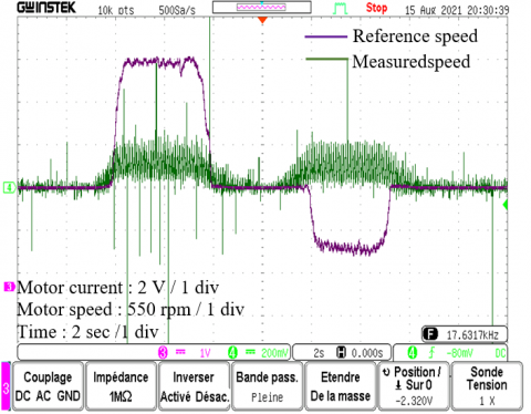
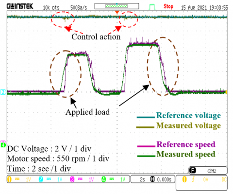
Figure 19 shows the speed responses when the DC voltage equals zero. When operating at high speed, we observe the collapse and total degradation of the control due to insufficient energy and the variation in the amplification gain of the variable speed drive. It can be seen that the PMDC is still turning at a low speed with a lot of oscillation and that’s when the regenerative braking takes a role in charging the battery via the bidirectional DC-DC converter.
There is also an increase in the width of the speed ripples around the setpoint due to the effect of measurement probes.
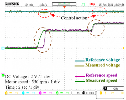
A staircase-style test with several reference speed levels was used. Figure 20 displays the speed control reaction. The drive remained stable as a result of these observations, and this condition may be preserved within the appropriate speed limits.
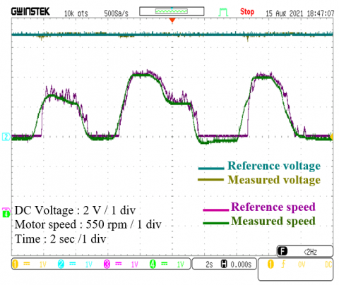
A benchmark reference is applied in Figure 21 and Figure 22, the reference speed varies from zero to different levels even at low speed.
The acquired findings, presented in Figure 22, clearly illustrate that the measured speed matches its reference completely with a tiny overshoot. At the observed speed, oscillations arise; these oscillations are caused by the measurement chain and the non-linearity of the electrical components employed in the assembly.
Figure 14. Motor speed response and DC voltage response. vbat=7 V (without regulation)
Figure 15. Motor speed response and DC voltage response in case of energy recovery
Figure 16. Speed response in case of battery discharge
Figure 17. DC voltage regulation response with electric braking applied
Figure 18. Performance tracking of motor speed regulation response for benchmark reference
Figure 19. Speed response in the case of applied torque
Figure 20. Speed response and DC voltage regulation with the DC-DC buck-boost converter
Figure 21. PMDC motor speed variation with sudden changes in the reference speed
Figure 22. Motor speed regulation and voltage responses
This paper introduced a real-time implementation of a small electric vehicle application based on a direct current-based buck-boost converter and a four-quadrant DC converter connected to a permanent magnet DC motor. This implementation aims to improve the dynamic and energy performance of the system, allowing the motor to work in four operating configurations as well as keeping the bidirectional energy flow in the traction system, most notably during regenerative braking.
The proposed traction system has been subjected to a model reference fuzzy adaptive control. Experimental tests have been carried out with and without the bidirectional DC-DC converter. The results indicate a severe degradation in performance in its absence, while a good operation was obtained when the converter was used.
The adaptation of this control method was motivated by its ability to handle the unknown parameter variations and external disturbances, which is ideal for electric vehicle applications.
The proposed scheme shows promising performance in terms of speed control at different operating modes and in terms of keeping the voltage constant for a long time in case of battery discharge. Future work will focus on enhancing the power quality by adding filters to the system.
|
EVs |
Electric Vehicles |
|
4-Q |
Four-quadrant |
|
DC |
Direct current |
|
PMDC |
Permanent magnet direct current |
|
MRAFC |
Model reference adaptive fuzzy control |
|
FLC |
Fuzzy logic controller |
|
SOC |
State of charge |
|
Fadd |
Aerodynamic drag force |
|
Fcr |
Climbing and downgrade resistance force |
|
Fro |
Rolling resistance force, N |
|
Fsf |
Stokes or viscous friction force, N |
|
Fw |
Road load force, N |
|
g |
gravity acceleration, m.s2 |
|
G |
Gear speed ratio |
|
i |
Transmission ratio |
|
Ibat |
Battery Current |
|
J |
Total inertia (rotor and load), kg m2 |
|
L (Lm) |
Inductance (magnetizing inductance) |
|
m |
vehicle total mass, kg |
|
p |
pole-pair number |
|
PI |
Proportional Integral Controllers |
|
Pv |
Vehicle driving power, W |
|
r |
tire radius, m |
|
R |
Resistance, Ω |
|
TB |
Load torque accounting for friction |
|
Tem |
Electric motor torque |
|
TL |
Load torque |
|
Tr |
Rotor time constant (Tr=Lr/Rr) |
|
Ts |
Stator time constant (Ts=Ls/Rs) |
|
v |
Vehicle speed, m/s |
|
α |
Road angle slope, rad |
|
δ |
Steering angle, rad |
|
ηt |
Transmission efficiency |
|
ξ |
air density, kg/m3 |
|
σ |
Leakage coefficient, σ=1-L2 m/Ls Lr |
|
φ |
Flux of motor, Wb |
|
ωr |
Electric motor mechanical speed, rad/s |
|
$\omega_{r}^{*}$ |
Reference Electric motor mechanical speed, rad/s |
[1] Berigai Ramaiaha, A., Maurya, R., Arya, S.R. (2018). Bidirectional converter for electric vehicle battery charging with power quality features. International Transactions on Electrical Energy Systems, 28(9): e2589. https://doi.org/10.1002/etep.2589
[2] Araria, R., Negadi, K., Boudiaf, M., Marignetti, F. (2020). Non-linear control of DC-DC converters for battery power management in electric vehicle application. Przeglad Elektrotechniczny, 10(48): 3-20. https://doi.org/10.15199/48.2020.03.20
[3] Naseri, F., Farjah, E., Ghanbari, T. (2016). An efficient regenerative braking system based on battery/supercapacitor for electric, hybrid, and plug-in hybrid electric vehicles with BLDC motor. IEEE Transactions on Vehicular Technology, 66(5): 3724-3738. https://doi.org/10.1109/tvt.2016.2611655
[4] Arof, S., Diyanah, N.H.N., Noor, N.M.N., Radzi, M., Jalil, J.A., Mawby, P.A., Arof, H. (2019). Series motor four quadrants drive DC chopper. In Progress in Engineering Technology, pp. 155-167. https://doi.org/10.1007/978-3-030-28505-0_12
[5] Wu, F., Fan, S., Li, X., Luo, S. (2019). Bidirectional buck–boost current-fed isolated DC–DC converter and its modulation. IEEE Transactions on Power Electronics, 35(5): 5506-5516. https://doi.org/10.1109/TPEL.2019.2947079
[6] Heydari, S., Fajri, P., Rasheduzzaman, M., Sabzehgar, R. (2019). Maximizing regenerative braking energy recovery of electric vehicles through dynamic low-speed cutoff point detection. IEEE Transactions on Transportation Electrification, 5(1): 262-270. https://doi.org/10.1109/TTE.2019.2894942
[7] Liang, J., Walker, P.D., Ruan, J., Yang, H., Wu, J., Zhang, N. (2019). Gearshift and brake distribution control for regenerative braking in electric vehicles with dual clutch transmission. Mechanism and Machine Theory, 133: 1-22. https://doi.org/10.1016/j.mechmachtheory.2018.08.01
[8] Liu, W., Qi, H., Liu, X., Wang, Y. (2020). Evaluation of regenerative braking based on single-pedal control for electric vehicles. Frontiers of Mechanical Engineering, 15(1): 166-179. https://doi.org/10.1007/s11465-019-0546-x
[9] Sankardossa, V., Geethanjali, P. (2017). Parameter estimation and speed control of a PMDC motor used in a wheelchair. First International Conference on Power Engineering Computing and Control (PECCON-2017), pp. 345-352. https://doi.org/10.1016/j.egypro.2017.05.142
[10] El-Samahy, A.A., Shamseldin, M.A. (2018). Brushless DC motor tracking control using self-tuning fuzzy PID control and model reference adaptive control. Ain Shams Engineering Journal, 9(3): 341-352. http://dx.doi.org/10.1016/j.asej.2016.02.004
[11] Yin, H.Q., Yi, W.J., Li, C.C., Wang, K.J., Wu, J.T. (2020). The fuzzy adaptive PID control of brushless DC motor. In Journal of Physics: Conference Series, 1507(5): 052005. http://dx.doi.org/10.1088/1742-6596/1507/5/052005
[12] Amir, A., Che, H.S., Amir, A., El Khateb, A., Abd Rahim, N. (2018). Transformerless high gain boost and buck-boost DC-DC converters based on extendable switched capacitor (SC) cell for stand-alone photovoltaic system. Solar Energy, 171: 212-222. https://doi.org/10.1016/j.solener.2018.06.078
[13] Bouradi, S., Araria, R., Negadi, K., Marignetti, F. (2020). Nonlinear control of permanent magnet synchronous motor for high performances electric vehicle. TECNICA ITALIANA-Italian Journal of Engineering Science, 64(2-4): 317-324. https://doi.org/10.18280/ti-ijes.642-429.
[14] Araria, R., Negadi, K., Marignetti, F. (2019). Design and analysis of the speed and torque control of IM with DTC based ANN strategy for electric vehicle application. TECNICA ITALIANA-Italian Journal of Engineering Science, 63(2-4): 181-188. https://doi.org/10.18280/tiijes.632-410
[15] Mokrani, Z., Rekioua, D., Mebarki, N., Rekioua, T., Bacha, S. (2017). Proposed energy management strategy in electric vehicle for recovering power excess produced by fuel cells. International Journal of Hydrogen Energy, 42(30): 19556-19575. http://dx.doi.org/10.1016/j.ijhydene.2017.06.106
[16] Tan, R.H., Hoo, L.Y. (2015). DC-DC converter modeling and simulation using state space approach. In 2015 IEEE Conference on Energy Conversion (CENCON), pp. 42-47. http://dx.doi.org/10.1109/CENCON.2015.7409511
[17] Guldemir, H. (2011). Modeling and sliding mode control of DC-DC buck-boost converter. In Proc. 6th Int. Advanced Technological Symp, pp. 475-480.
[18] Ben-Yaakov, S., Hadad, Y., Diamantstein, N. (2006). A four quadrants HF AC chopper with no deadtime. In Twenty-First Annual IEEE Applied Power Electronics Conference and Exposition, APEC'06, p. 5. http://dx.doi.org/10.1109/APEC.2006.1620732
[19] Tiwari, S., Rajendran, S. (2019). Four quadrant operation and control of three phase BLDC motor for electric vehicles. In 2019 IEEE PES GTD Grand International Conference and Exposition Asia (GTD Asia), pp. 577-582. http://dx.doi.org/10.1109/GTDAsia.2019.8715878
[20] Negadi, K., Boudiaf, M., Araria, R., Hadji, L. (2022). Improvement of the amplification gain for a propulsion drives of an electric vehicle with sensor voltage and mechanical speed control. Smart Structures and Systems, 2(5): 661-675. https://doi.org/10.12989/SSS.2022.29.5.661
[21] García-Sánchez, J.R., Hernandez-Marquez, E., Ramírez-Morales, J., Marciano-Melchor, M., Marcelino-Aranda, M., Taud, H., Silva-Ortigoza, R. (2019). A robust differential flatness-based tracking control for the “MIMO DC/DC Boost converter–inverter–DC motor” system: Experimental results. IEEE Access, 7: 84497-84505. http://dx.doi.org/10.1109/ACCESS.2019.2923701
[22] Moussavi, S.Z., Alasvandi, M., Javadi, S. (2012). Speed control of permanent magnet DC motor by using combination of adaptive controller and fuzzy controller. International Journal of Computer Applications, 52(20).
[23] Shahgholian, G., Maghsoodi, M., Mahdavian, M., Janghorbani, M., Azadeh, M., Farazpey, S. (2016). Analysis of speed control in DC motor drive by using fuzzy control based on model reference adaptive control. In 2016 13th International Conference on Electrical Engineering/Electronics, Computer, Telecommunications and Information Technology (ECTI-CON), pp. 1-6. http://dx.doi.org/10.1109/ECTICon.2016.7561239
[24] Alset, U., Apte, A., Mehta, H. (2020). Implementation of fuzzy logic based high performance speed control system for PMDC motor using ATMEGA-328P-PU Micro-controller. In 2020 IEEE International Conference on Electronics, Computing and Communication Technologies (CONECCT), pp. 1-5. http://dx.doi.org/10.1109/CONECCT50063.2020.9198569
[25] Belkhir, K.S. (2020). Simple implementation of a fuzzy logic speed controller for a PMDC motor with a low cost Arduino mega. Engineering, Technology & Applied Science Research, 10(2): 5419-5422. https://doi.org/10.48084/etasr.3340