K. Barathi* | P.K. Dhal
© 2022 IIETA. This article is published by IIETA and is licensed under the CC BY 4.0 license (http://creativecommons.org/licenses/by/4.0/).
OPEN ACCESS
A new approach for single phase grid interconnected PV module with SEPIC converter is introduced in this paper. As the outcome of PV is low voltage DC, a suitable converter is needed to boost the voltage. Hence SEPIC converter is used as it has high voltage gain with same polarity in the input as well as output side. A closed loop control is executed with a PI controller tuned with Cuckoo search (CS) algorithm. As the traditional tuning of PI controller results in peak overshoot problems, Cuckoo search (CS) based Optimization is utilized as it is simple with has a smaller number of tuning parameters. This output is being fed to the grid through a single phase VSI and the grid synchronization is accomplished by PI controller by analogizing the actual and reference values of power. Thus, the proposed control strategy is verified through MATLAB and it is observed that the source current THD is minimized, which satisfies the IEEE standard.
PV system, SEPIC converter, MPPT algorithm, CS algorithm, DC-DC converter
In the recent days, the Photo voltaic energy is widely utilized in all the countries and the Governments are trying to find more ways to satisfy the electrical requirements of the country with solar energy. Practically it is easier to implement and cost effective than other sources, which includes complex installation with highly expensive units of power generation; adding to that, this PV power is non-polluting and it requires less maintenance, because of which it is highly preferable in multiple structures. The photovoltaic power generators can be kept or installed at any place and the operation of PV is safe and quiet. In photo voltaic technique, the power is generated when the semiconductors material is hit by the sunlight. In the PV fed system, the input current with discontinuous operation and oscillatory output voltage have been gained with the effect of partial shading and highest ripple. A PV fed zeta converter is developed by evaluating the mathematical notations [1]. The MPPT algorithm is utilized for tracking the output power from the PV panel and this technique includes SEPIC converter with PWM for reducing the difficulty of the system [2]. A buck converter is developed with zeta, which includes inductors and capacitors by utilizing a sliding mode controller, the performance of which is compared with other converters [3]. For wind power generation, a synchronous generator with permanent magnet is linked with rectifiers. The reference voltage is made as constant with respect to the voltage in the open circuit of zeta converter yet maintaining a stable voltage is difficult [4]. Pazhampilly et al. [5] have discussed about the PV fed MPPT technique with incremental conductance feedback current and voltage. In consideration with various types of converters, MPPT is presented for extricating the power from PV system and the total output power of the system is comparatively lower than the other existing techniques. In this works [6], a fuzzy logic controller (FLC) is utilized for the extraction of highest output power. The FLC has utilized the Mamdani’s technique as the convergent and divergent membership function of PV system. A zeta converter is fed with PV array for MPPT [7]. The Researchers have evaluated the fuzzy logic controller, which utilizes the code tree format along with the P&O algorithm of MPPT tracking in the PV panel [8]. AC voltage is generated by utilizing a Zeta converter and the generated power is given to the 3-phase rectifier by providing the desired outputs [9]. BLDC motor with minimum switching losses including a tracking Algorithm is utilized [10]. P & O control technique is utilized for PV system with MPPT and a comparison is done between the SEPIC and BOOST converter [11]. A modified SEPIC converter is created for minimal switching voltage and high static gain, along with that, a modified SEPIC configuration is used through magnetic coupling to attain reduced input voltage performance [12].
A modified MPPT technique is utilized for SEPIC converter with fuzzy logic control for limiting the voltage variation [13-16]. A PV fed SEPIC converter is presented with fuzzy controller [17]. Fuzzy is used for maintaining the voltage as constant at various load conditions. A modified technique for solar PV voltage tracking is utilized with SEPIC convertor. Incremental conductance technique is utilized for MPPT and implemented in MATLAB [18, 19]. The performance of the system with respect to THD & Output efficiency is differentiated by the converter [19]. Hence the desired output voltage is gained by setting the output voltage [20]. Though there are a number of developed methods and modified techniques, each of them has lacked in a certain criterion. Hence in this work, a single-phase PV integrated grid with SEPIC converter is analyzed, in which a closed loop control is executed by cuckoo search-based optimization thereby retaining the link voltage. Grid synchronization is also accomplished by a PI controller.
The organization of the paper is as follows: the description of the proposed system is given in section 2 and in section 3, the analysis of the PV model; the proposed converter and its control algorithm are presented. The results and discussion of the proposed work are given under section 4, with the conclusion following in section 5.
In this proposed work, the input voltage of the converter is fed from solar PV panel. The arrangement of PV fed grid connected system is shown in Figure 1. Conversion of DC-DC is highly recommended for attaining the required voltage from PV. As CUK and buck boost converters have led to stress in electrical components and ends up with failure in device or overheating. SEPIC converter is utilized here since it overcomes the mentioned disadvantages. The output of converter is given to single-phase inverter whose switches are controlled by PI controller. via suitable filter circuits, the inverter output is given to utility grid.
Figure 1. Proposed system block diagram
SEPIC has a distinctive operation i.e. the output voltage polarity is as similar as the input voltage polarity and the power has been transmitted from the input to output through the capacitor coupling. When converter is set in the on state due to coupling capacitor, L1 gets charged from the source whereas coupling capacitor gets decreased when the converter is set to off state. L1 is charged by the coupling capacitor and the energy, which has been transferred from L2 to output and diode is forward biased. SEPIC converter operates in two modes called continuous and discontinuous conduction modes. The current, which has been presented in the inductor is always higher than zero during continuous conduction mode while operating in full load; the total efficiency is always better. The current in the inductor is minimized to zero in Discontinuous conduction mode and remains in zero for specific switching cycle periods. It starts from zero and attains peak value then falls to zero if the duty cycle is high and thus the output is high. The output voltage of SEPIC is determined through duty cycle. It is capable of producing non inverted output by utilizing the coupling energy through series capacitor from input to output. SEPIC converter mainly focuses on frequency ripple suppression. It maximizes the total function of the system with minimal duty yield and maximum voltage gain in output. The efficacy of the converter has been maximized by utilizing CS Algorithm with MPPT technique. With the help of non-linear loads, reactive power is increased in the grid side. Due to non-linearity in grid characteristics, the current has become non-uniform so the quality of power is literally reduced and it affects the grid performance. Hence PI controller is utilized for the compensation in grid current and the developed methodology attains maximum compensation in grid current. The developed methodology is a grid integrated technique without any storage system. SEPIC converter with Cuckoo Search Algorithm has increased the efficiency of the system by 96%. The circuit layout of this system is remarkably highlighted in Figure 2.
Figure 2. Proposed system circuit diagram
A 10 KHz triangular carrier and reference signal are differentiated, along with that, the pulses are fed to the SEPIC. In the developed technology, MPPT algorithm is utilized to attain stability in output voltage with lowest ripples, and the voltage source inverter is fed by the obtained voltage. The 1Φ VSI changes the DC into AC with pulsated output. Due to non-linearity in loads, the harmonics have been fed to the voltage and current, so the actual and reference power are analogized thereby the reactive power compensation, thus the PI based grid synchronization is accomplished.
A) Modelling of PV Panel
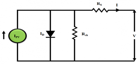
A traditional PV system is presented in Figure 3.
Figure 3. Model for one diode PV system
where, the PV current is denoted as lPV, diode current is denoted as ID, the resistance in series is denoted as Rs the resistance in shunt is denoted as Rsh, the output current is denoted as I and the output of PV voltage is denoted as V.
Photo Voltaic panel current is given below;
$I=I_{P V}-I_{O}\left[e^{\frac{\left(v+R_{S} I\right)}{V_{k} \propto}-1}\right]-\frac{V+I R_{S}}{R_{S h}}$ (1)
where, IO represents PV saturation current, Vk represents the high thermal voltage and $\alpha$ represents the ideality constant of diode.
Four Photo Voltaic panels are used in this proposed method. SEPIC converter is fed by the obtained photo voltaic output.
B) SEPIC Converter
The input voltage can be increased or decreased through a converter known as SEPIC Converter. This is basically a boost converter, in which the operation is differentiated in two modes. They are:
CCM
In this mode, the current in the inductors L1 and L2 is constant and never drops to zero, which prevents the inductance from fully discharged. Cin is equal to that of Vin during the steady state operation of SEPIC converter and the current flowing through Cin is 0A. Output load is independent of Vin and is equivalent to the average current of L2.
In CCM, sum of voltage across the energy storage element of SEPIC converter has been equivalent with input voltage (input and output filter capacitors Cin and Co are excluded) which is given below,
$V_{\text {in }}=V_{L 1}+V_{C i n}+V_{L 2}$ (2)
Here the average voltage across Cin is same as Vin,
$\mathrm{V}_{\mathrm{L} 1}=-\mathrm{V}_{\mathrm{L} 2}$ (3)
In steady state, CCM of SEPIC converter takes place in two ways based on the ON and OFF state of switch S. To study the function of SEPIC converter in CCM, it is essential to know the condition of switch S.
ON state of switch S
Figure 4 explains the function of SEPIC converter in the ON state of switch S. In steady state, no current has been flowed through the filter capacitors Cin and Co till they are discharged. Ripple in the SEPIC’s converters input and output voltages becomes zero when the capacitance Cin and Co are large.
Figure 4. Switch on condition
During the first half-switching cycle i.e., in ON state, the current through L1 and L2 have increased both in positive and negative direction. Here L1 and L2 have charged and discharged through Vin and Cin. In the short period of time, the switch S remains closed, at this instant, the instantaneous voltage across Cin is equal to Vin. VL1 and VL2 are equal with magnitude Vin.
OFF state of switch S
Figure 5 explains the operation of SEPIC when switch S is open or in OFF state. L1 and Cin are the new path for the input current. Inductor current has not changed immediately since the inductor L1 is equal to the capacitor current Cin and current L2 remains to discharge. Co discharges in the half-switching cycle thus D turns on and supplies the current to the load.
Figure 5. Switch off condition
Here, the input current is added by the current flows in the direction of L2, which also flows to the output load that draws current from the inductance L1 and L2 when the switch S is in the OFF state. Cin is charged by Vin and L1 (when switch S conducts during half switching cycle is discharged), and to the next half switching cycle, the switch S conducts the current to the load output till L2 continues in discharging (L2 is charged by the current that is supplied by Cin).
DCM
The inductor current becomes zero in this mode of operation. For significant time period, the current through L1 and L2 remain at 0A. In less load current, it has maximum efficiency while operating this converter in DCM but needs more operating at maximum load current. Hence it yields more efficiency in this operation. SEPIC converter contains capacitance and Inductance, which aids to work in continuous mode with respect to the duty cycle in Eq. (4).
Duty Cycle:
$D=\frac{V_{{OUT}}\,\,+V_{{D}}}{V_{{IN}}\,\,+V_{{AN}}\,\,+V_{{D}}}$ (4)
where, VOUT represents the output voltage, VD represents the voltage across the diode and VIN represents the input.
Inductor and capacitor output value has been given as,
$L_{1}=L_{2.3}=\frac{V_{I N} \times D_{\max }}{I_{1} \times f_{S}}$ (5)
$\mathrm{C}_{2}=\frac{{I}_{0} \,\,\times {D}_{\max }}{{V}_{\text {ripple }} \,\,\times \mathrm{V}_{\mathrm{D}} \times \mathrm{f}_{\mathrm{S}}}$ (6)
Io =Current output
Vripple = Voltage ripple
Dmax = Diode maximum value
VD = Voltage in Diode
fs = Switching frequency
Load Resistance is given as,
$\mathrm{R}=\frac{\text { Vout }}{\text { Iout }}$ (7)
Here Vout and Iout represents the output Voltage and current respectively.
Current through the inductor is given as,
$\Delta \mathrm{I}_{\mathrm{L}}=\frac{\text { IouT.V }_{0} \cdot 40 \%}{\mathrm{~V}_{\mathrm{IN}}}$ (8)
RMS current in the output capacitor is given as,
$\mathrm{I}_{\text {out }}(\mathrm{RMS})=\mathrm{I}_{\text {OUT }} \times \sqrt{\frac{\text { Dmax }}{1-\text { Dmax }}}$ (9)
RMS current of coupling capacitor is given as,
$I_{\mathrm{C} 1}(\mathrm{RMS})=I_{\mathrm{IN}} \times \sqrt{\frac{\text { Dmax }}{1-\text { Dmax }}}$ (10)
Voltage ripple of coupling capacitor C1 has been mentioned as,
$\Delta \mathrm{VC 1}=\frac{{I}_{{OUT}}\,\,\, \times {D}_{{Max}}}{{C}_{1} \times {F}_{{S}}}$ (11)
C) Control Strategies for SEPIC converter
Proper control of SEPIC converter is vital and this is accomplished by CS algorithm, which results in uniform output voltage of the converter. A comparator is utilized for differentiating the actual and reference values of link voltage. The error signal is given to PI controller and by CS Algorithm, the control parameters are turned as fine. As a result, reference signal is generated by the controlled parameters and differentiated with the carrier wave. Owing to this, pulses are generated and fed to SEPIC converter.
Cuckoo search Algorithm
The Cuckoo Search (CS) algorithm is influenced through the breeding performance of cuckoos, which is introduced by Yang and Deb. An impressive aspect of certain cuckoo species is the parasitism of the brood. In the nests of other birds, female cuckoos lay their eggs, which looks the same or different. If the host bird finds out the egg, these alien eggs are killed or the nest is destroyed and a new one is established at anywhere. Cuckoos use various techniques namely mimicking the colors of host eggs, selects finest nest and improves the ability to imitate the call of host chick to maximize the feeding opportunities to rise the chance of producing a novel cuckoo and to decrease the possibility of the demolition of eggs by the host birds. The parasitism of cuckoo brood is listed below,
1. Every cuckoo puts single egg and randomly dumps it into the nests of another bird species.
2. The Finest nests has been taken for the next generation of high quality eggs.
3. The quantity of available host nests has been set and it is often possible for host bird to find the cuckoo’s eggs and throw it out. The pseudo code for CSO is illustrated as follows:
|
Start Objective function $F(x), x=\left(x_{1}, \ldots \ldots x_{n}\right)^{t}$. Create the size of initial population n. Host nests $X_{i}=(i=1,2, \ldots \ldots n)$. While $(t<$ max. generation $) /$ (stop criterion) Attain a cuckoo randomly by levy flight. Analyze its fitness value Fi. Select a nest amidst n i.e. j randomly. If $\left(F_{i}>F_{j}\right)$ Use instead of j by the novel value; End Abandoned the fraction (Pa) of poor nests; Additionally, built new ones; Save nest with adequate solutions Rank the solution and choose the best current End While. Print the outputs Stop |
To efficiently hunt for a novel nest, the performance of cuckoos is related with Levy flights in CSA. Levy flights illustrate the method of random walks, which are defined by the phase lengths and followed a distribution of power law. The Levy flight is expressed as,
$x_{i}^{g+!}=x_{i}^{g}+\alpha^{\prime} \otimes \operatorname{Lev} y\left(\lambda^{\prime}\right)$ (12)
where, the number of current generation is denoted as g, i.e. $g=1,2, \ldots$ max $-$ cycle and the number of pattern is denoted as $i, \alpha^{\prime}>0$ is the Levy flight’s step size that controls the flight scale, entry-wise multiplication is denoted as $\otimes$, Levy supply includes endless changes with the endless mean, which is denoted as $Levy\left(\lambda^{\prime}\right)$.
$\operatorname{Levy}\left(\lambda^{\prime}\right) \sim s^{-\lambda^{\prime}}$ avec $\left(1<\lambda^{\prime} \leq 3\right)$ (13)
where, the step size is denoted as s. Through the similar performance of a constant Levy supply, two generally dispersed stochastic random parameters have produced the transfer possibility to shift it from the current position to the next position. The generation of next nests is expressed as,
$x_{i}^{g+!}=x_{i}^{g}+$ stepsize.randn (14)
where, the random value between zero and one has been denoted as randn. The step size is expressed as:
stepsize $=\alpha^{\prime} .$ step. $\left(x_{i}-x_{\text {best }}\right)$ (15)
where, the $\left(x_{i}-x_{\text {best }}\right)$ is the difference factor which is utilized to choose the apt results. The step factor has been expressed as,
step $=\left(\frac{\sigma\left(\lambda^{\prime}\right) \cdot \operatorname{ran} d n}{\operatorname{randn}}\right)^{\frac{1}{\lambda^{\prime}}}$ (16)
where, the standard deviation is denoted as $\sigma$ and it is expressed as,
$\sigma\left(\lambda^{\prime}\right)=\left(\frac{\Gamma\left(1+\lambda^{\prime}\right) \cdot \sin \left(\pi \lambda^{\prime} / 2\right)}{\Gamma\left(\left(\frac{1+\lambda^{\prime}}{2}\right) \cdot \lambda^{\prime} \cdot 2 \frac{\lambda^{\prime}-2}{2}\right)}\right)^{\frac{1}{\lambda^{\prime}}}$ (17)
The strength of the CS algorithm lies in how the solution space is manipulated and explored by a cuckoo. To find best solutions, this cuckoo has some ‘intelligence’. The PI controller is tuned with CS algorithm and depending on the tuned parameters, the pulses for the SEPIC converter is generated with the aid of PWM generator.
The construction of $1 \Phi$DC link potential controller of PV inverter is given in Figure 6. The PV inverter voltage (Vdc) has been given to LPF to minimize the ripples in switching. The filtered DC link potential and reference voltage $\left(V_{d c}^{*}\right)$ is given to PI to control the DC link voltage.
Figure 6. Grid synchronization by PI controller
The voltage error (Verr) in nth sampling instant is given as,
$\left.\Delta v_{e r r}(n)=v_{d c}^{*}(n)-v_{d c}(n)\right)$ (18)
The output of PI at nth sampling time is,
$\begin{aligned} i_{i n v}^{*}(n)=i_{i n v}^{*}(n&-1) \\ &+K_{P 1}\left(\Delta v_{e r r}(n)-\Delta v_{e r r}(n-1)\right) \\ &+K_{I 1} \Delta v_{e r r}(n) \end{aligned}$ (19)
where, dc voltage controller proportionality is denoted as KP1 and integral gain is denoted as KI1. The reference currents have been generated with integrated grid potential for the PV inverter. Through this technique, PV inverter is highly proficient in generating the local load along with high current to reference value. When the requirement of load is greater than the production of PV, the grid has provided the necessitated currents.
The actual current in the inverter is compared with reference value in this mode of conduction. The output of PI has produced a change in the duty cycle (d) and it is combined with the static duty ratio to generate the modulating signal.
Table 1. Specifications for solar panel
|
COMPONENTS |
RATINGS |
|
Number of panels |
3 |
|
Number of cells in series |
36 |
|
Cell |
125mm×31.25mm |
|
OC voltage |
21.4 V |
|
Optimal operating voltage |
16.8 V |
|
SC current |
1.21 A |
|
Optimal operating current |
1.19 A |
|
Operating temperature |
-40 to + 850C |
|
Maximum system voltage |
1000 V DC |
Table 2. Specifications of SEPIC converter
|
Components |
Symbols |
Rating |
|
Input Voltage |
Vin |
0 to 100 V DC |
|
Input Current |
ii |
25 A (Max) |
|
Capacitances |
C1,C2 |
20 uF |
|
Inductances |
L1,L2 |
7 mH |
|
Output load current |
IL |
5 Amps |
|
Switching frequency |
f |
10 KHZ |
|
Output Power |
P0 |
700 W |
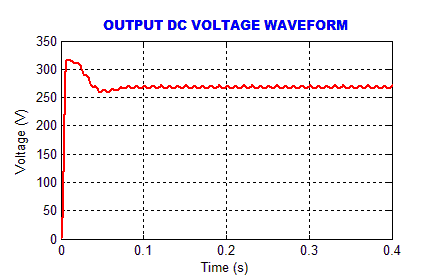
A closed loop control of PV integrated grid with SEPIC converter by CS algorithm is analyzed by using MATLAB/SIMULINK. The voltage ratings of solar system and SEPIC Converter has been represented Tables 1 and 2. The simulated results have been highlighted and discussed in the following subsection.
Figure 7. Simulated waveform of input DC voltage to SEPIC converter
The Figure 7 exhibits the SEPIC converter solar voltage. Owing to variation in solar panel input, output solar voltage has high ripples and that is given to the SEPIC.
Figure 8. Simulated waveform of input current from SEPIC converter
The Figure 8 presents the waveform of input inductor current in SEPIC converter, L1 in SEPIC converter has controlled the input current as constant.
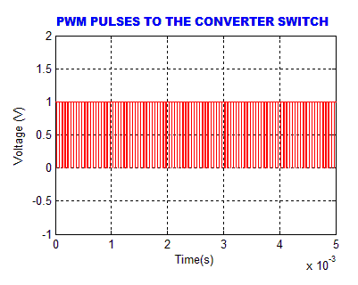
Figure 9. Simulated output of PWM pulse to SEPIC converter
The Figure 9 exhibits the PWM pulses for the SEPIC converter, which are generated by CS algorithm with switching frequency of 10 kHz. The CS algorithm is an optimized self-tuning algorithm.
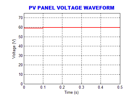
The Figure 10 exhibits the SEPIC converter output voltage by utilizing CS algorithm and it is observed that, comparatively CS algorithm provides more stability in voltage than MPPT algorithms [21].
Figure 10. Simulated output voltage of SEPIC converter by utilizing CS algorithm
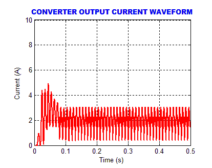
Figure 11. Simulated output DC current of SEPIC converter
(a)
(b)
Figure 12. a Simulated waveform of grid voltage; b Simulated waveform Of Grid current
The Figure 11 exhibits SEPIC converter output current waveform, owing to noises in nonlinear load current.
The grid current compensation is accomplished by a PI controller. Figure 12.a and 12.b presents grid voltage and current waveforms correspondingly, which implies that both voltage and current are in phase i.e., unity power factor is attained. This presentation resembles a STATCOM device.
Figure 13. Simulated waveform of Current THD with CS algorithm
As represented in Figure 13, it is validated that the proposed single-phase grid tied PV system delivers a THD of 3.7%, which satisfy the IEEE standard.
PV based integrated grid with SEPIC has been explained in this work and the system’s behavior is analyzed through MATLAB. A closed loop control is accomplished with a PI controller tuned with CS algorithm which provides minimum ripple with the aid of SEPIC. Through PI, the grid synchronization has been attained by comparing the reference and actual values of power thereby minimum THD is achieved. The power quality issues and standard theory levels of harmonics have been maintained by the inverter. The SEPIC with CS algorithm gives good performance than others, which has been validated through the simulated results. The proposed system is utilized in reactive power compensation and in the power grids.
[1] Sowmya, N., Raj, S., Urmila, B. (2013). PV fed Zeta converter. International Journal of Engineering Research and Applications (IJERA), 3(4): 2692-2696.
[2] Ganesh, S., Janani, J., Angel, G.B. (2014). A maximum power point tracker for PV panels Using SEPIC converter. International Journal of Computer and Systems Engineering, 8(2): 356-361. https://doi.org/10.5281/zenodo.1091692
[3] Vijay, K.O., Sriramalakshmi, P. (2016) Comparison between zeta converter and boost converter using sliding mode controller. International Journal of Engineering Research & Technology (IJERT), 5(7): 368-373.
[4] Keerthana, R., Chintu. N.J. (2017). Performance analysis of zeta converter in wind power application. Asian Journal of Applied Science and Technology (AJAST), 1(3): 199-203. http://ajast.net/data/uploads/3ajast-49.pdf.
[5] Pazhampilly, R., Saravanan, S., Babu, N.R. (2015). Incremental conductance based MPPT for PV system using boost and SEPIC converter. ARPN Journal of Engineering and Applied Sciences, 10(7): 2914-2919.
[6] Jadhav, V., Nagarale, R.M. (2016). Maximum PowerPoint tracking of PV system based on a SEPIC converter using fuzzy logic controller. Journal of Engineering Research and Applications, 6(1): 59-64.
[7] Anand, R., Deepika, M.C. (2017). Solar PV array employing zeta converter based MPPT controller supplying BLDC motor drive. Advances in Natural and Applied Sciences, 11(7): 15-25. http://www.aensiweb.net/AENSIWEB/anas/anas/2017/May/15-25.pdf.
[8] Priya, J.S., Ambika, A., Haritha, L. (2018). Fuzzy logic controller based MPPT for photovoltaic system using ZETA converter. International Journal of Pure and Applied Mathematics, 119(12): 2905-2911. https://acadpubl.eu/hub/2018-119-12/articles/7/1822.pdf.
[9] Justin, B.J., Reddy, S.R., Mercy, D., Arofant, V.P., Mani, M. (2018). PMSG fed zeta converter based micro wind energy conversion system. International Journal of Pure and Applied Mathematics, 119(12): 15545-15552.
[10] Satheesh R., Aarthy, M., Sathyan, G., Meena, S., Jenifa, R.S.S. (2018). Solar PV array employing zeta converter based MPPT controlled BLDC motor. Global Research and Development Journal for Engineering, 1: 234-239.
[11] Banaei, M.R., Shirinabady, M.R., Mirzaey, M. (2014). MPPT control of photovoltaic using SEPIC converter to reduce the input current ripples. Journal of Engineering Research and Applications, 4(1,4): 160-166.
[12] Sakthivel, C., Selvakumar, K., Venkatesan, T. (2016). Modified SEPIC converter with high static gain for renewable energy applications. Journal of Control Theory and Applications, 9(37): 865-873.
[13] Shiv Kanth, B.V.N.V., Sainath, C.V.S., Sandeep, G. (2015) PV fed modified SEPIC converter. International Journal of Scientific & Engineering Research, 6(3): 542-552.
[14] Gujar, S.S., Keswani, V.H. (2017). SEPIC converter for maximum power tracking of photovoltaic systems by using fuzzy logic. International Journal of Engineering Trends and Technology (IJETT), 43(2): 97-101.
[15] Verma, C., Kumar, B.A. (2016). Comparison of dc-dc converters with SEPIC converter for wind driven Induction generators. International Journal of Engineering Trends and Technology (IJETT), 39(4): 180-183. https://doi.org/10.14445/22315381/IJETT-V39P231
[16] El Khateb, A., Abd Rahim, N., Selvaraj, J., Uddin, M.N. (2014). Fuzzy-logic-controller-based SEPIC converter for maximum power point tracking. IEEE Transactions on Industry Applications, 50(4): 2349-2358. https://doi.org/10.1109/TIA.2014.2298558
[17] Thomas, L.A., Abraham, M., James, J.M. (2016). MPPT technique using SEPIC converter to track maximum power point for PV panel. International Journal of Scientific & Engineering Research, 7(4): 675-682.
[18] Bhavin, T., Patel, B., Desai, J., Sonwane, K. (2018). Analysis of SEPIC converter. IJEDR, 6(2): 489-495.
[19] Devi, S.L., Nagarajan, S., Vaishali, R. (2019). Design, analysis and comparison of suitable converters for photovoltaic system. International Journal of Recent Technology and Engineering (IJRTE), 7(5S2): 205-21.
[20] Manimegalai, D., VishnuPriya, Lavanyaa, Parkavi. (2017). High gain interleaved SEPIC converter using sliding mode controller in discontinuous conduction mode (DCM) for reducing switching losses. Journal of Chemical and Pharmaceutical Sciences, 3(8): 33-38.
[21] Mohammed, O.A., Katta, P., Senthil, K.R., Yugin, M., Dhiwakar, M., Chandru, S., Manikandan, P. (2021). Solar PV based super lift LUO converter for BLDC motor drive. Journal of Physics: Conference Series, 1916: 012144. https://doi.org/10.1088/1742-6596/1916/1/012144