Mohammad Awwad Ali Al-Dabbas
© 2021 IIETA. This article is published by IIETA and is licensed under the CC BY 4.0 license (http://creativecommons.org/licenses/by/4.0/).
OPEN ACCESS
Ejectors are a kind of pump that does not have any moving components. In certain cases, the motor fluid may be a liquid, steam, or another gas. The research focuses on using nano adsorption combined with a multi ejector to fuel a sophisticated nano adsorption power plant, which is equipped with three shapes of steam boiler generators. The simulation was accomplished by implementing it with the cooperation of the two programs MATLAB A and MATLAB B, together with a solid flow. To raise the temperature of the working fluid before it enters the generator, a jet pump is positioned before the generator. To enhance the mass flow rate of vapor going into the ejector, a two-stage adjustable booster was added after the evaporator, which gives low evaporator temperature. A further experiment in which the two-stage adjustable booster was used before the generator to reduce the amount of work done by the generator. The ejector's cooling unit is powered by steam created from many energy sources powered by advanced hybrid heat and power systems, including solar energy and steam produced by the electric steam generator. The different devices are either directly triggered by a thermal source to achieve heating, cooling, or refrigeration. The steam boiler generator is the core of the cooling unit; in this research, various types of steam boiler generators are linked with adsorption units, such as steam-powered solar boilers, gas boilers, solid fuel steam boilers, and electric boilers. Heat exchangers were utilized to transfer heat from the solar chimney to the ejector cooling unit. The impact of various ejector geometries on the advanced cooling unit was studied and simulated for the single, double, and triple nozzle ejector. There were no issues with the more effective cooling unit. This unit performed better than traditional adsorption cooling units, having a greater efficiency.
solar cooling, ejector refrigeration, cop, multi-stage ejector, booster, steam jet ejector, adsorption refrigeration, geothermal, solar chimney, MATLAB, solid flow
As it is very simple and inexpensive when compared to absorption refrigeration, ejector refrigeration is an excellent alternative. An ejector heat pump is a heat-driven cycle that may use various energy sources such as solar, waste, or natural gas, as well as hybrid combinations (for example, solar/gas).
Environmentally safe refrigerants may be used in the thermal cooling technique based on ejector cooling machines, which can use solar, waste, or exhaust heat.
ECMs may be operated by sophisticated hybrid heat and power systems that use heat obtained by the system. Production or cogeneration is an old method for practical energy usage. Advanced hybrid heating, cooling, and electricity production can be accomplished by using a process called trigeneration, although it is a very new technology, and it will be used more often as an energy-saving alternative for small-scale applications. The ejector chillers and air conditioners may be used to build and develop various kinds of micro-trigeneration systems.
Several researches on solar ejector cooling are referenced in the literature as shown in Figures 1 and 2. A theoretical study describes collector selection by Huang et al. Although using flat-plate collectors is more cost-effective than using collectors of a vacuum tube, it is determined that their high price makes the use of vacuum collectors economically appealing despite their inferior efficiency.
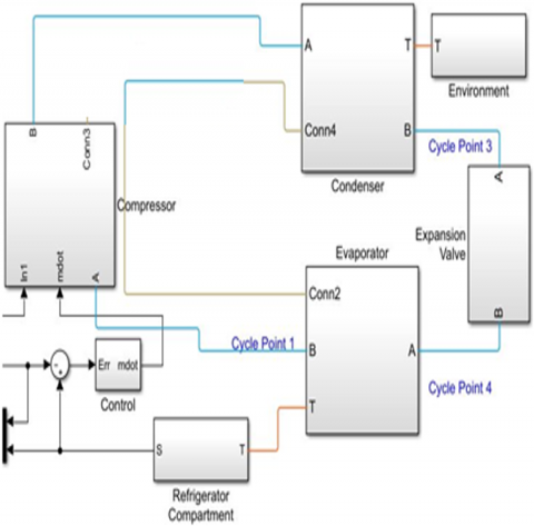
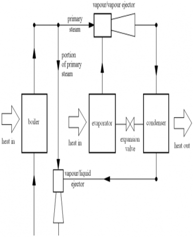
Figure 1. Steam adsorption refrigeration cycle schematic without ejector
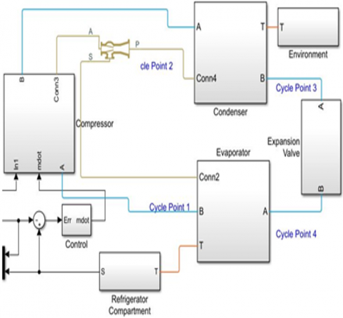
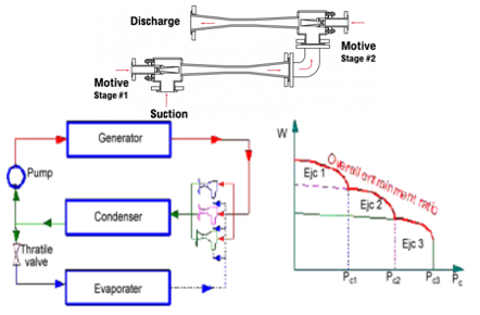
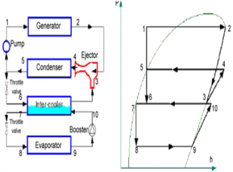
Figure 2. Steam generator different types in hybrid nano adsorption– the multi-stage cooling cycle in ejector
The study by Chen et al. [5] examined current advancements in ejectors, including their use in refrigeration. The ease of design, installation, and maintenance are advantageous with ERS systems compared to old vapor compression systems. The compression in an ERM is possible without mechanical energy need. Even further, using thermal energy with low overall grade (like solar and waste heat by industries) may assist reduce CO2 emissions by mitigating issues such as pollution caused by burning fossil fuels.
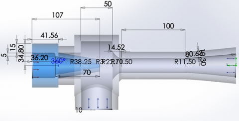
Figure 3. The ejector's layout
The ejectors are considered a type of pump without any moving components within the ejector system as shown in Figures 3 and 4. The evaporator, condenser, ejector, expansion valve, and pump are the components of a single system. Because it contains few moving elements, the ejector is simple in design. It is also likely to last longer because that does not create noise or vibration, and it uses vapor compression instead of heat compression. Though their performance coefficient is lower than those mechanical compressor-based air-conditioning systems, ejector cooling technologies have become well-known due to growing awareness and pressure for preserving the environment, which has helped improve their performance coefficient [1].
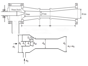
Figure 4. Conservation of energy in ejectors [1]
Ejectors are operated by thermal sources like waste heat, heat from renewable resources, and powered by waste heat or renewable heat resources, enabling them to provide heating, cooling, or refrigeration. When it comes to the enormous potential effects of ejectors, they could be employed in various situations. This component could be installed in an air conditioning, heat pump, and refrigeration system to enhance system effectiveness. To improve the system's worldwide performance, they might be utilized in hybrid systems as an ejector-compression or ejector-absorption system.
Two and three-stage ejectors might be either condensing, or non-condensing kinds depend on the usage of auxiliary equipment. Almost all of four, five, and six-stage units, although if they are non-condensing, are almost always condensing units.
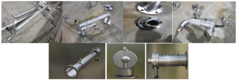
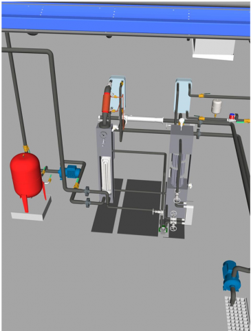
Figure 5 shows the ejector's manufacture and assembly that built and operated successfully.
Figure 5. The ejector's manufacture and assembly
3.1 Dual ejector system
Steam Jet Vacuum device using the technology of the steam jet ejectors with multi-stages Lowering the absolute pressure of suction records in need of an ejector staging, which helps to save money. In general, condensing and non-condensing ejectors may be utilized for two and three-stage applications. The two-stage steam jet ejector has a broad range of use, like a single-stage steam jet ejector. Non-condensable gases and vapors, as well as the combination of the both, are also handled.
Figure 6. Dual ejector [15]
The most functioning of the dual ejector system are providing the equivalent force to the ejecting shell as a single ejector but require only half of the spring force per spring to accomplish the task. The force per spring is lower promoting longevity in the spring coil and extending the life of the ejection system. Also, they provide three points of contact on the ejecting shell rim instead of the two contact points on a single ejection system. The three-point contact promotes more consistent ejection angles from the receiver port.
One of the most telling indicators of pumping effectiveness within the ejector is the ratio of entrainment, while the other is pump output (mass flow rate ratio between primary and secondary fluids). An entrainment ratio over the target level will lead to increased fluid carrying capacity and better pumping efficiency. It is also called pressure gain. Pressure gains are given the opposite name (critical pressure), which means that the ratio of entrainment is the same at pressures lower than critical pressure. The greater the critical pressure, the less frequently the foreline pump will need to operate due to the reduced back pressure.
Ejector results are affected by many operational factors, including the back-pressure. When changing the back-pressure parameters of the ejector, the law of entrainment ratio has been studied in the ejector to see whether there is a change. Then, the diversity of the ejector's usual internal flow field is examined to find the inherent reason for a change in pumping performance. Figure 6 shows the steam ejector with the choking and shock wave phenomena that directly affect pumping performance. To further understand the ratio besides critical pressure, it is essential to look at the functional area size at the chocking point and the mass flow of the secondary fluid.
3.2 The ejectors may be utilized in the following application [16]
3.3 Multi stage ejector [2, 4, 16-18]
A two-stage system operating in a low vacuum or high vacuum includes the main high vacuum ejector and a low secondary vacuum ejector as shown in Figure 7. Firstly, the ejector of low vacuum is utilized to increase the vacuum in the system by pulling the vacuum down from the beginning pressure to an intermediate pressure. When this pressure is met, the ejector of high vacuum is started, and the ejector of low vacuum is simultaneously run, with the high vacuum ejector acting as the auxiliary to achieve the necessary vacuum.
Figure 7. Multi-stage ejector [17]
Two-stage systems that are either condensing or non-condensing are possible. Depending on their function, condensers may be employed as pre, inter, or after-condensers, all of which decrease the amount of gas that is sent on to the following ejector stage. In addition, smaller ejectors could be utilized inside the system, which reduces the quantity of motive steam required. Non-condensing systems might also be employed, depends on the application, although they are less efficient than condensing systems since each ejector must take in the whole gas load from the preceding stage. A large ejector can result from this, as can an increase in the quantity of motive steam used. The non-condensing varieties are often utilized when installing condensers would be impractical or when service is intermittent, making running expenses a minor concern as shown in Figure 8.
Figure 8. Refrigeration unit with booster [17]
3.4 Dual-nozzle ejector [19]
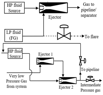
Multiple ejectors may be connected in series to utilize the recovered exit pressure if lower than needed for flowing pipeline lines or separators as shown in Figure 9.
Figure 9. Two ejectors in series for boosting pressure of very low-pressure gas [19]
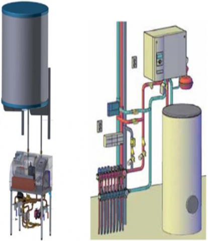
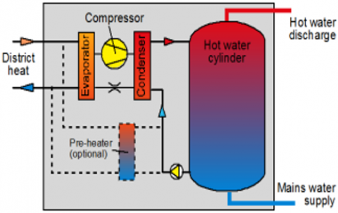
3.5 The booster heat pump
Booster heat pumps as shown in Figures 10 and 11 have a thermal capacity of 2 kW. These models are intended to raise hot water to 70 degrees Celsius utilizing a heat source with a temperature of 40 degrees Celsius. Braber c.s developed a unique idea that used an innovative energy solution that was being utilized in the new local heating system called Waalsprong, which utilized a low-temperature district heating network for thermal energy, and household booster heat pumps for domestic hot water [20].
Figure 10. Heat pumps with booster: Left: Ecoon and right: Alfa Innotec [20]
Figure 11. Basic layout of a booster heat pump [20]
3.6 The hydrodynamic characteristic inside the ejector
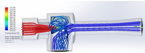
Figures 12-17 show the simulation result of the hydrodynamic characteristic inside the ejector.
The simulation was accomplished by implementing it with the cooperation of the two programs MATLAB A and MATLAB B, together with a solid flow inside the ejector.
Figure 12. Utilizing MATLAB function to simulate the distribution of pressure within the ejector
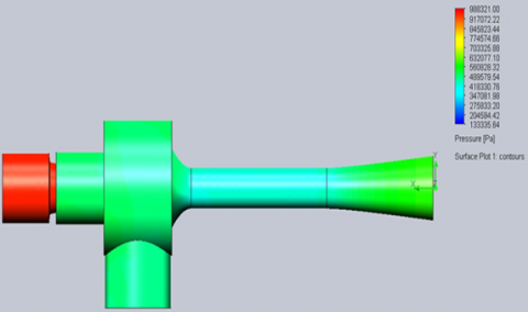
Figure 13. Utilizing solid flow to simulate the distribution of pressure within the ejector
Figure 14. Utilizing solid flow to simulate the pressure distribution within the ejector
Figure 15. Simulation of dynamic pressure distribution inside of the ejector using solid flow
Figure 16. Simulation of temperature distribution inside of the ejector using solid flow
Figure 17. Simulation of velocity within the ejector (hydrodynamic)
4.1 Nano adsorption cooling system [21-23]
Figure 18 shows the new unit that was developed at Mutah University. A unique device composed of a flat plate generator, condenser, and evaporator contains the most significant parts. This device utilizes adsorbent– Activated carbon and methanol refrigerant combinations, respectively. The copper plate collector was built using a flat-plate solar collector. It was coated with a specific coating to increase the collector's solar absorption capability. Condenser tube, evaporator, and the refrigeration chamber, which was manufactured of copper tubing. The collector-evaporator unit was developed where the cycled methanol exchange area, the atmosphere, and the methanol free space are all considered. The evaporator is housed within a refrigerated chamber. Evaporate tor cools the surrounding air in the chamber over the adsorption phase of the cycle. To minimize the effect of air appearance on the methanol cycle, the vacuum pump was employed. Moreover, a liquid nitrogen trap was used during pumping to capture the methanol vapor as it was generated.
Figure 18. Nano adsorption–cooling system [22]
The improved hybrid adsorption–ejection cycle has been developed to address this drawback of intermittently operating in the adsorption cooling unit.
To enhance the coefficient of performance, various design changes were performed on the nano adsorption cooling unit, and the result was that the cooling temperature was kept low.
Several adjustments have been accomplished to the hybrid adsorption–evaporation cycle to meet these needs:
4.2 Advanced hybrid Nano adsorption–ejector refrigeration system
The advanced hybrid system has four subsystems: condenser, adsorber, ejector, and evaporator (Figure 19) [24].
In the daytime, the adsorber uses water desorbing from the activated carbon to collect solar energy. When the adsorber is linked with the ejector, the evaporator refrigeration system begins. Water vapor from activated carbon, which is at high pressure and temperature, is inserted into the ejector and shot via the convergent-divergent nozzle. As the main flow approaches a supersonic velocity, the suction exit has a lower pressure and higher vapor entrainment as valve three opens. The mixture of the two streams flows up to the entrance of the constant-area portion under consistent pressure. Hypothetically, the water vapor’s temperature, besides pressure, reaches mid-values in the ideal process, and the mixture is compressed into the condenser by the diffuser. At this step, the water vapor’s temperature and pressure cool into liquid, which is then sent to the receiver, and finally returns to the evaporator by the throttle valve. Adsorber valves are switched throughout the afternoon so that the adsorber isn't linked with the ejector anymore, and the adsorber is instead linked with the evaporator. At some point in the adsorption refrigeration process, the pressure within the adsorber must be lowered to the point of P e. Refrigeration is essential during the freezing and thawing periods. The following day until the next day is the period covered.
Figure 19. Schematic of the hybrid nano adsorption solar-supported ejector cooling system representation [9]
4.3 Ejector cooling system operated by solar power [21-26]
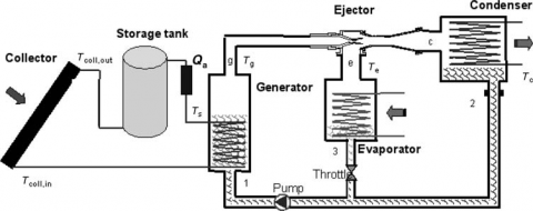
The combination of cooling demands and available solar radiation is often in phase, making solar-powered refrigeration extremely appealing. The circuit diagram in Figure 20 shows it comprises a collector circuit and an ejector cooling system. Solar collector circuit components include a collecting array, a storage tank, and an auxiliary heater, which is a constant-temperature heat source to generate constant generator inlet temperature (Tg). At higher pressure, the refrigerant is vaporized on the ejector cycle side of the generator. Through the ejector, the main flow produces low pressure at the outlet portion. The secondary flow within the evaporator that helps provide the cooling effect is entrained in this low-pressure environment. The shear layer occurs in the suction chamber's converging part, and a sonic-velocity secondary fluid is created (mixing). The last shock occurs, resulting in a subsonic downstream state once the mixing process is finished. Once the diffuser pressure has been set to the condenser conditions, the pressure is raised in the subsonic diffuser to compensate. When all the condensate is pumped back to the generator from the evaporator, the cycle is finished. For example, you will find an extensive description of the ejector action, for instance, in Eames et al. [7].
Due to the considerably reduced auxiliary heating needs, the vacuum tube solar collectors are considered more appealing than flat-plate solar collectors. Water was utilized as the working fluid [4]. For ECM, traditional flat plate and vacuum tube solar collectors may be powered by standard single-glazed flat plate solar collectors, or the system can be more affordable using a selective surface collector. A solar ECM can provide cooling in the range of evaporation temperatures of 12°C to -10°C for air-conditioning, space-cooling, and food storage. The test site in the UK was able to achieve an appealing COP of 0.3. Water was employed as the refrigerant in the research by Khattab and Barakat [5] that was given as a modeling example.
Figure 20. Schematic of an experimental setup with an ejector
Figure 21. Experimental setup without an ejector schematic
4.4 Air conditioners with solar multi-stage ejector [26-28]
For air conditioning, an ejector system works by harnessing the energy from the sun using a solar collector and an ECM-powered heat pump. The solar generator utilizes the energy in sunlight to power the ECM. In the closed-type ejector, the necessary heat is provided by intermediate heat-transfer liquid, usually, water which is heated in a solar collector, as shown in Figures 20-21. They depict the open-loop method of heating water in which the condenser is first cooled to reduce the condensing temperature and boost ejector chiller efficiency [2].
Thermally powered steam ejector (SER) or steam ejector heat pump (SEHP) systems appear to be viable technologies for heating and cooling. When it comes to finding a new solution for the heating and cooling emissions problem, the quickest way is to apply an absorption refrigeration (AR)/heat pump (AHP) system. This way, the HVAC system only needs to handle the necessary cooling and heating loads, not the vapor-compression heat pump's higher needs of heating and cooling. As opposed to vapor compression systems, absorption systems are bulkier.
The steam generator is most often manufactured of steel and is a closed vessel. It carries heat generated by the burning of fuel from the fuel supply to water, and it is utilized to produce steam.
Wood, coal, diesel, natural gas, and electricity are all fuels that could be utilized to fuel boilers that are an essential element of the Chemical Industries. In general, boilers used to produce steam fall into three categories: gas boilers, water tube boilers, and packaged boilers; Fluidized Bed FBC boilers, and steam solar-powered generators.
To operate the unit of ejector cooling, multiple steam boilers were utilized. These current steam boilers demonstrate how ejector cooling devices powered by these boilers could be developed. There are many kinds of liquid fuel, gas, and solid fuel.
5.1 Steam generator operated by solar power
In this research, many solar-powered steam generators were utilized.
● The previous nano adsorption unit was operated by solar power
* Steam boiler generator operated by a solar generator that has been evacuated.
* The collector of Fresnels. One of the linear Fresnel collector modules for industrial use. A higher operating source temperature of 180°C-210°C is thus now needed.
5.2 Combined Electrical Steam jet boiler -ejector cooling unit [17-19, 28]
Steam is generated by electric power instead of fuel combustion in an electric steam boiler. Though the high operating costs of gas or oil-fueled boilers compared to alternative heating systems, the popularity of gas/oil-fuelled boilers depends on their simplicity and accessibility. For industrial purposes, electric boilers are best used for vast quantities of water that need to be turned into steam in a short period of time.
The Electrical Steam jet boiler, as shown in Figure 1. Pipes made of stainless steel were utilized for the evaporator and boiler. Condenser cooling coil made of copper tubing wrapped in two spirals. A receiver tank is attached to the condenser's outlet. This tank acts as a condensate reservoir. Brass is utilized for the ejector's primary nozzle and spacers. An integral piece of PVC is utilized for the secondary nozzle on the ejector.
Typical stainless steel is used for the ejector's exterior body where the nozzle is located. Bathes are implemented in experiments. The water level in the sight glass before each test run is set to a preset level using municipal tap water.
An electric vacuum pump is linked to the top of the boiler elements and connected to the boiler's boiler valve, which has been closed. The vacuum pumps are used to remove air from the system while the boiler is heating up. It has no valves connecting the steam pipe, ejector assembly, condenser, and evaporator, and each is linked to the others via the steam pipes, ejector assemblies, evaporators, and condensers. The vacuum pump is attached to the top of the ejector T-piece. The boiler valve is opened when the boiler is reached its working temperature. The pipe that connects the boiler and ejector may be heated with this device. It helps to expel any remaining air from the connecting pipe as well. The boiler valve is opened just for a short time (as little as five seconds) before it is closed. A few times while the vacuum pump is operating, the boiler valve is opened and closed. It will continue until the connecting pipe has been emptied and the remainder of the system.
The boiler's water level is then raised to the preset level, and the boiler valve is closed. Boiling is completed, and the boiler is returned to working temperature. To activate the cooling water supply to the condenser, power is sent to the condenser, and the data logger is turned on. The boiler valve is turned on to start a test run.
5.3 Integrated Water Tube Boiler-ejector cooling unit
A tube containing water surrounded by hot gases and flames, and fire is termed a water tube.
5.4 Packaged boiler
High heat transfer efficiency, excellent thermal efficiency, better combustion efficiency, and efficient evaporation. About 99 percent of chemical industries, boilers are water tube boilers.
5.5 Ejector cooling unit for an advanced hybrid steam oil shale combustion generator
Solid fuel combustion was manufactured and utilized to produce steam, and the oil shale combustor unit was matched with the ejector cooling unit.
5.6 Geothermal ejector cooling unit with advanced hybrid steam underground technology
Steam was produced by drilling a horizontal loop into the oil shale; the combustion unit in the oil shale combustor was paired with an ejector cooling unit.
5.7 Solar chimney ejector cooling unit with the hybrid technology
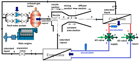
Figure 22 shows the waste heat that used to power the ejector fridge system.
Figure 22. waste heat powered steam ejector fridge system [38]
5.8 Gas steam boiler
It is made of cast iron and titanium for strength. Traditional radiator systems may be easily incorporated with this product.
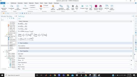
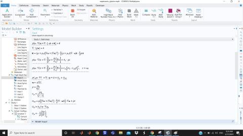
5.9 The implemented equations
Figure 23. Flow properties conditions
Figure 24. Thermal conductivity equation
Figure 25. Dynamic viscosity equation
Figures 23-26 show the implemented equations that were used to simulate flow characteristics, while Figures 27-32 show the result of simulation.
Figure 26. Density equation
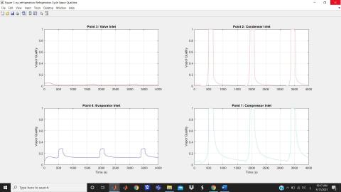
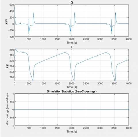
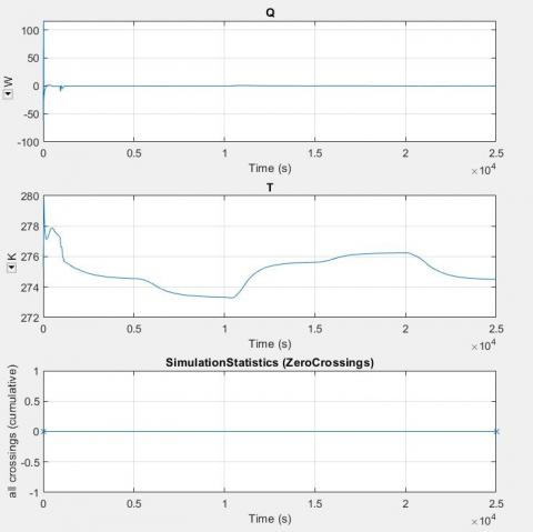
Figure 27. Refrigeration cycle quality
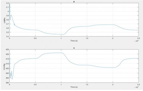
Figure 28. Simulation of the compressor's pressure and internal energy without an ejector
Figure 29. Simulation of the compressor's pressure and internal energy with an ejector
Figure 30. The cooling outlet temperature without an ejector
Figure 31. The cooling outlet temperature with an ejector
Figure 32. Wall temperature of the evaporator without an ejector
Figure 33. Wall temperature of the evaporator with an ejector
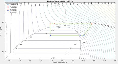
Figure 34. Specific enthalpy without ejector
Figure 35. Specific enthalpy with ejector
Finally Figures 33-35 shows the Wall temperature of the evaporator with an ejector, while figure the Specific enthalpy with and without ejector element.
The COP is employed to evaluate the thermodynamic performance of steam ejectors. The ratio of evaporator heat load to boiler energy input and pump work ratio are the two factors that contribute to this ratio.
To this ratio. The COP is calculated as follows:
$COP=\frac{{{Q}_{evap}}}{{{Q}_{boiler}}+{{W}_{pump}}}=\frac{{{P}_{evap(elec)}}}{{{P}_{boiler(elec)}}}=\frac{{{(VI)}_{evap}}}{{{(VI)}_{boiler}}}$
Many Jet ejector kinds have been examined, with some being simulated while others were created and successfully functioned at boiler temperatures below 100 degrees Celsius.
Comparing solar-powered steam jet air conditioning unit to traditional vapor-compression air conditioning unit, this research found that solar-powered steam jet air conditioning unit was effective and practical.
The closed-loop system performance at comparable boiler temperatures and cost-effective production techniques.
An upgraded cooling system for multi-stage ejectors was produced.
Over a wide variety of operating circumstances, the modified advanced hybrid adsorption cycle outperforms the basic cycle, regarding the findings.
Over the standard cycle, the improved cycle's COPs increased by 8–60% at condenser temperatures of 25–45°C and by 30–85% at evaporator temperatures of 0–10°C, according to the findings.
A combination of MATLAB and solid flow was employed to simulate the thermal and hydrodynamic properties of advanced adsorption solar units combined with or without ejector units.
On the opposite side, the ejector unit that was assembled with a previously built solar adsorption unit.
However, the ejector unit was manufactured and assembled in conjunction with the solar adsorption system that had been previously produced.
[1] Ma, X., Zhang, W., Li, F., Riffat, S.B. (2019). Solar ejector cooling technologies. Advanced Energy Efficiency Technologies for Solar Heating, Cooling and Power Generation, pp. 287-309. https://doi.org/10.1007/978-3-030-17283-1_8
[2] Petrenko, V.O., Huang, B.J., Shestopalov, K.O. (2011). Innovative solar and waste heat driven ejector air conditioners and chillers. Proceedings of the 2011 2nd International Conference on Environmental Science and Technology IPCBEE (International Proceedings of Chemical, Biological and Environmental Engineering), Singapore, pp. 338-343.
[3] Eicker, U. (2009). Low Energy Cooling for Sustainable Buildings. John Wiley & Sons.
[4] Huang, B.J., Petrenko, V.A., Samofatov, I.Y., Shchetinina, N.A. (2001). Collector selection for solar ejector cooling system. Solar Energy, 71(4): 269-274. https://doi.org/10.1016/S0038-092X(01)00042-1
[5] Chicco, G., Mancarella, P. (2007). Trigeneration primary energy saving evaluation for energy planning and policy development. Energy Policy, 35(12): 6132-6144. https://doi.org/10.1016/j.enpol.2007.07.016
[6] Petrenko, V.O. (2009). Application of innovative ejector chillers and air conditioners operating with low-boiling refrigerants in trigeneration systems. EUROTHERM SEMINAR (No. 85).
[7] https://www.moldmakingtechnology.com/careers/how-to-choose-the-correct-ejector-pin, accessed on 12 June 2021.
[8] Pranav, K., Ranjan, H.K., Singh, M.P. (2014). A study and analyze of an ejector in steam power plant. International Journal of Engineering and Management Research (IJEMR), 4(3): 195-199.
[9] Varga, S., Oliveira, A.C., Diaconu, B. (2009). Analysis of a solar-assisted ejector cooling system for air conditioning. International Journal of Low-Carbon Technologies, 4(1): 2-8. https://doi.org/10.1093/ijlct/ctn001
[10] Nguyen, V.M., Riffat, S.B., Doherty, P.S. (2001). Development of a solar-powered passive ejector cooling system. Applied Thermal Engineering, 21(2): 157-168. https://doi.org/10.1016/S1359-4311(00)00032-6
[11] Khattab, N.M., Barakat, M.H. (2002). Modeling the design and performance characteristics of solar steam-jet cooling for comfort air conditioning. Solar Energy, 73(4): 257-267. https://doi.org/10.1016/S0038-092X(02)00067-1
[12] Chunnanond, K., Aphornratana, S. (2004). Ejectors: Applications in refrigeration technology. Renewable and Sustainable Energy Reviews, 8(2): 129-155. https://doi.org/10.1016/j.rser.2003.10.001
[13] Eames, I.W., Aphornratana, S., Haider, H. (1995). A theoretical and experimental study of a small-scale steam jet refrigerator. International Journal of Refrigeration, 18(6): 378-386. https://doi.org/10.1016/0140-7007(95)98160-M
[14] Pridasawas, W. (2006). Solar-driven refrigeration systems with focus on the ejector cycle (Doctoral dissertation, KTH). Ph.D. Thesis. Royal Institute of Technology, Stockholm, Sweden.
[15] Shen, S.Q., Qu, S.P., Zhang,B., Riffat, S., Gillott, M. (2005). Study of a gas–liquid ejector and its application to a solar-powered bi-ejector refrigeration system, Applied Thermal Engineering, 25(17-18): 2891-2902, https://doi.org/10.1016/j.applthermaleng.2005.02.012
[16] Huang, B.J., Chang, J.M., Wang, C.P., Petrenko, V.A. (1999). A 1-D analysis of ejector performance. International Journal of Refrigeration, 22(5): 354-364. https://doi.org/10.1016/S0140-7007(99)00004-3
[17] Zhuo, H., Zhao, H.X., Yu, Z.T., Han, J.T. (2018). Simulation and optimization of a R744 two- temperature supermarket refrigeration system with an ejector. International Journal of Refrigeration, 90. https://doi.org/10.1016/j.ijrefrig.2018.04.007
[18] Sonawat, A., Sama, A. (2012). Flare gas recovery using ejector - a review. Proceedings of the Thirty Ninth National Conference on Fluid Mechanics and Fluid Power, SVNIT Surat, Gujarat, India.
[19] Sarshar, M.M., Beg, N.A., Andrews, I. (2003). The applications of jet pumps as a cost effective way to enhance gas production and recovery. Proceedings of Indonesian Petroleum Association, 2: 1-11. https://doi.org/10.29118/ipa.2305.03.e.059
[20] Kleefkens, O. (2017). Booster heat pump, development of test procedure and calculation methodology in order to estimate the energy performance in various domestic applications. 12th IEA Heat Pump Conference.
[21] Al-Dabbas, M.A. (2012). The performance of the first Jordan Badia’s solar powered refrigerator. Applied Solar Energy, 48(3): 175-179. https://doi.org/10.3103/S0003701X12030036
[22] Al-Dabbas, M.A. (2013). The performance of Nano adsorption solar cooling generator unit. 2013 1st International Conference & Exhibition on the Applications of Information Technology to Renewable Energy Processes and Systems, Amman, Jordan, pp. 55-59. https://doi.org/10.1109/IT-DREPS.2013.6588150
[23] Al-Dabbas, M.A. (2015). Performance evaluation of hybrid photovoltaic and thermal solar collector in Jordan. Distributed Generation and Alternative Energy Journal, 30(2): 8-22. https://doi.org/10.1080/21563306.2015.11431661
[24] Jrad, A.B.H., Hamida, M.B.B., Ghnay, R., Mhimid, A. (2017). Contribution to the study of combined adsorption–ejection system using solar energy. Advances in Mechanical Engineering, 9(7). https://doi.org/10.1177/1687814017711855
[25] Phogat, R. (2018). Study on performance enhancement of solar ejector cooling system. International Refereed Journal of Engineering and Science (IRJES), 6(8): 1-6. http://dx.doi.org/10.22214/ijraset.2018.6134
[26] Steam jet cooling. Wikipedia, the Free Encyclopedia. en.wikipedia.org/wiki/Steam_jet_cooling, accessed on 12 June 2021.
[27] Evaluation of Steam Jet Ejectors. www.scribd.com/doc/106123569/Evaluation-of-Steam-Jet-Ejectors.
[28] Meyer, A.J., Harms, T.M., Dobson, R.T. (2009). Steam jet ejector cooling powered by waste or solar heat. Renewable Energy, 34(1): 297-306. https://doi.org/10.1016/j.renene.2008.03.020
[29] Majdi, H.S. (2016). Performance evaluation of combined ejector LiBr/H2O absorption cooling cycle. Case Studies in Thermal Engineering, 7: 25-35. https://doi.org/10.1016/j.csite.2016.01.003
[30] Gao, Y., He, G., Cai, D., Fan, M. (2020). Performance evaluation of a modified R290 dual-evaporator refrigeration cycle using two-phase ejector as expansion device. Energy, 212: 118614. https://doi.org/10.1016/j.energy.2020.118614
[31] Visedmanee, J., Pongtornkulpanich, A., Somkun, S., Ananchai, U. (2015). Experimental investigation of solar-driven double ejector refrigeration system. Journal of Renewable Energy and Smart Grid Technology, 10(1): 13-26.
[32] Abdella Mohammed, Y.G., Suriwong, T., Somkun, S., Maroyi, T.M. (2016). Exergy analysis of a solar-driven dual parallel-connected ejector refrigeration system. Applied Mechanics and Materials, 839: 100-106. https://doi.org/10.4028/www.scientific.net/AMM.839.100
[33] Sioud, D., Garma, R., Bellagi, A. (2018). Thermodynamic analysis of a solar combined ejector absorption cooling system. Journal of Engineering, 2018: 7090524. https://doi.org/10.1155/2018/7090524
[34] Power, R.B. (1994). Steam Jet Ejectors for the Process Industries. McGraw-Hill.
[35] Kneass, S.L. (1984). Practice and Theory of the Injector. John Wiley & Sons.
[36] Anderson, D.N., O'Day, R.M.H. (2013). Cab-Forward Notes Southern Pacific Railroad's Signature Locomotive. Sacramento, California: Gerald Rood.
[37] Selvaraj, D.A., Victor, K. (2021). Design and performance of solar PV integrated domestic vapor absorption refrigeration system. International Journal of Photoenergy, 2021: 6655113. https://doi.org/10.1155/2021/6655113