Alief Wikarta* | Rizaldy Hakim Ash Shiddieqy | Khosmin | Indra Sidharta
© 2021 IIETA. This article is published by IIETA and is licensed under the CC BY 4.0 license (http://creativecommons.org/licenses/by/4.0/).
OPEN ACCESS
Indonesian engineers need to design and build their electric car chassis from scratch. These cars need to possess high torsional stiffness and maximum Von Mises Stress value. Therefore, this determines the value of Torsional Stiffness and Von Mises Stress from an electric car scratch chassis using Finite element simulation. A twist load was placed in front, with back support used to determine the torsional stiffness. The stress was analyzed using three types of loading, namely; vertical, lateral, and braking. Meanwhile, the JIS G 3141 galvanized plate with a thickness of 1 mm and 1.2 mm from Indonesia's marketplace was the chassis material used. The simulation results showed that the maximum Von Mises Stress value with a thickness of 1.2 mm produces safe strength, with a torsional stiffness of 11735 Nm/deg. In conclusion, the rigidity and strength of the chassis with a plate thickness of 1.2 mm is in a proper category. Furthermore, this chassis can be used for the development from scratch of an electric car.
electric car chassis, development from scratch, finite element simulation, torsional stiffness, stress analysis
The design and development of more environmentally-friendly electric cars is a primary concern of several countries, including Indonesia. This car, which uses energy stored in rechargeable batteries, is becoming popular and acts as an alternative to gasoline vehicles. Some famous automotive companies such as Mini, Audi, Volkswagen, Peugeot, Hyundai, BMW, Honda, Kia, Nissan, and Chevrolet already have electric cars [1, 2]. Tesla, which is one of the new automotive companies specializing in electric vehicles, is currently dominating the worldwide sale of the product [3, 4].
Electric cars are also needed in Indonesia to reduce pollution and the amount of fuel yearly imported. Unfortunately, the intense domination of Japanese brands has limited the research and development of electric vehicles [5-8]. Irrespective of this fact, Indonesian engineers need to design and build their electric cars from scratch. However, this alternative means of transportation cannot imitate conventional cars.
Chassis is the main component of a car. Most fuel tanks located at the rear of the chassis, strapped up tightly to the gasoline vehicle's undercarriage. Meanwhile, most electric car batteries are situated under the car beneath along the middle of the chassis. Therefore, engineers need to pay special attention to the area under the seat where the battery is placed [9, 10]. This ensures that batteries with large densities are assigned adequate space in the car to keep the chassis safe with sufficient weight, thereby enabling it to travel long distances. Besides, it also needs to be stiff in its compartment to achieve maximum performance while driving.
Therefore, based on these reasons, the main parameters that need to be fulfilled by the chassis are high torsional stiffness with the ability to achieve maximum Von Mises stress values [11-14]. Torsional stiffness is obtained by placing a twist on the front and back support [13], while the vertical, lateral, and braking load are used to determine the stress analysis [11].
Chassis are built using steel, aluminum, or magnesium materials with varying thicknesses plates [15-17]. In Indonesia, car materials are generally steel, provided by state-owned enterprises such as Krakatau-steel company [18]. Therefore, in this article, the scratch chassis material is the JIS G 3141 galvanized plate with thickness options of 1 mm and 1.2 mm.
Furthermore, engineering analysis is needed to choose the material and thickness suitable for an electric car chassis. Besides experimentation, a more comfortable and cheaper way used to design and develop electric cars is through finite element simulation [19-24].
Therefore, this article aims to determine the value of Torsional Stiffness and Von Mises Stress from an electric car scratch chassis using Finite element simulation. These simulation results are the design of the electric car with high Torsional stiffness value and safe stress analysis.
This research is structured as follows: The introduction contains the background of the study, the current state of the art of electric cars, explanations of the finite element simulation method, results and discussion of the simulation, and the chassis development process. It finally ends with a conclusion.
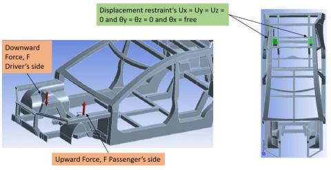
Figure 1. Boundary conditions to twist chassis models: applied torque in the front part and restraints at the rear
Before the simulation, the chassis needs to be drawn using Computer Aided Drawing (CAD), with the basic size adjusted to fit the designer team's description. Meanwhile, the thickness of the plates used are 1 mm and 1.2 mm. The chassis image obtained from CAD is exported to the Computer-Aided Engineering (CAE) software for finite element simulation uses the JIS G 3141 SPCD sheet metal produced by Krakatau Steel.
Table 1. Material properties of JIS G 3141
|
Physical properties |
Metric |
|
Density Hardness, Brinell Tensile Strength, Ultimate Tensile Strength, Yield Modulus of Elasticity Bulk Modulus Poissons Ratio |
7.872 g/cc 95 340 MPa 285 MPa 200 GPa 160 GPa 0.29 |
Table 1 shows that the properties material of JIS G 3141 is similar to AISI 1008 Steel, with Sy value of 285 MPa [25]. Meanwhile, the used meshing is the tetrahedron element with 83661 nodes and 42481 elements.
The vertical load needs to be given to the chassis' front and back to obtain the right torsional stiffness, as shown in Figure 1. The vertical deformation value is obtained from performed simulations and entered into Eqns. (1) - (3) to get the right Torsional Stiffness, as shown in Figure 2. The vertical load is also compared to the Torsional Stiffness of the cars in the marketplace. Therefore, the suitable plate thickness used as a chassis to build electric cars from scratch is determined as follows:
Equations and assumptions, from [13].
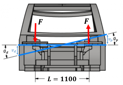
$K=\frac{\text { Torsion }}{\text { Twist angle }}=\frac{F . L}{0.5 .\left(\emptyset_{d}+\emptyset_{p}\right)}$ (1)
$\emptyset_{d}=\tan ^{-1}\left(\frac{v_{d}}{L / 2}\right)$ (2)
$\emptyset_{p}=\tan ^{-1}\left(\frac{v_{p}}{L / 2}\right)$ (3)
where, F: Vertical forces on the frame rails at a point in the vicinity of the front suspension pick-up points on the driver's and the passenger's side; L: Lateral distance between the driver and the passenger's load application points; $\emptyset_{d}$: Twist angle calculated from the vertical deflection of the frame rail on the driver's side; $\emptyset_{p}$: Twist angle calculated from the vertical deflection of the frame rail on the passenger's side.
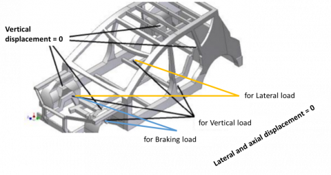
The vertical, lateral, and braking loadings are used to determine the chassis strength [26]. The vertical displacement suspension point for all types of loading is zero. Conversely, on lateral and axial displacement, arm points values are dependent on the type of loading, as shown in Figure 3.
Figure 2. Position of vertical force and twist angle in chassis used to determine torsional stiffness
Figure 3. Boundary conditions of displacement for the three types of loading conditions
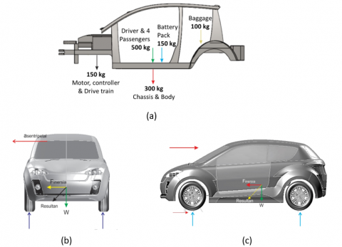
Figure 4 shows the loading conditions. In Figure 4 (a) the vertical load is derived from each component in the chassis that works on the weight point. While Figure 4 (b) shows the lateral load when turning at a speed of V = 30 km/h and a radius of R = 4.5 meters, with the emersion of centrifugal force and vertical load. Lastly, braking load is given when the car experiences a slowdown process of a = 9.6 m/s2; therefore, each component produces inertial force and a vertical load, as shown in Figure 4 (c).
The Von Mises stress analysis is used to determine the loading and sheet thickness of the simulation produced. Furthermore, the design is declared safe when the value of Von Mises stressed compared to the yield force is above 1.3.
Figure 4. Loading conditions for (a) vertical load, (b) lateral load, (c) braking load
The results of finite element simulation are shown in Figure 5 (a), with the vertical deflection due to twist load. Figure 5 (b) shows the maximum value of Von Mises Stress due to lateral load of sheet thickness of 1.2 mm, with the most critical position occurring in the battery compartment.
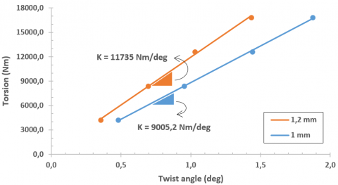
The vertical deflection is grouped, as shown in Table 2, until the twist angle value is obtained using Eq. (2) and (3). The chassis torsional stiffness (K) is the ratio of the change in the chassis' torsion to change the twist angle. Knowing the geometrical quantities and the value of the applied load can estimate the torsion. By using the twist angle in Table 2, we can calculate the chassis' torsional stiffness.
The torsion and twist angle values are inserted into Eq. (1) and plotted on the chart to obtain the torsional stiffness, as shown in Figure 6. The torsional stiffness of the chassis with a thickness 1.2 mm is more rigid compared to 1 mm. Stiff chassis feels more responsive in transient cornering, while a compliant chassis feels laggy. Also, a stiff chassis allows for the suspension to be turned more effectively.
The value of torsional stiffness for passenger cars in this study is in the range of 5000 - 20000 Nm/deg [22, 27-29]. This shows that JIS G 3141 material with a thickness of 1.2 mm produces a good torsional stiffness for chassis development from scratch design at 11735 Nm/deg.
Figure 5. Simulation results for sheet thickness 1.2 mm, (a) Vertical deflection with vertical load 15288 N, (b) maximum Von Mises stress of lateral load
Table 2. Vertical deflection and twist angle from finite element simulation
|
Vertical Force |
Torsion |
Vp |
Vd |
Twist angle |
|
|
(N) |
(N-m) |
(m) |
(m) |
(deg) |
|
|
1,2 mm |
3822 |
4204.2 |
0.003378 |
0.003428 |
0.354653 |
|
7644 |
8408.4 |
0.006560 |
0.006746 |
0.693417 |
|
|
11466 |
12612.6 |
0.009759 |
0.009990 |
1.029174 |
|
|
15288 |
16816.8 |
0.013726 |
0.013798 |
1.434372 |
|
|
1 mm |
3822 |
4204.2 |
0.004610 |
0.004609 |
0.480434 |
|
7644 |
8408.4 |
0.009140 |
0.009124 |
0.951801 |
|
|
11466 |
12612.6 |
0.013670 |
0.013970 |
1.440417 |
|
|
15288 |
16816.8 |
0.017948 |
0.017988 |
1.872750 |
Figure 6. Torsional stiffness of electric car chassis from finite element simulation
Figure 7. Summary Von Mises Stress of electric car chassis from finite element simulation
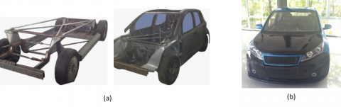
Figure 8. Chassis of electric-car, (a) fabrication process, (b) final prototype
Furthermore, the maximum Von Mises Stress simulation results are graphed with various loading conditions and sheet thickness. Figure 7 showed that the maximum value of Von Mises Stress under lateral conditions exceeds the material's yield strength at a thickness of 1 mm. Therefore, it is dangerous to be used in building an electric car chassis from scratch.
According to previous studies, the plate with a thickness of 1.2 mm also has a high value of Torsional Stiffness. Therefore, the results can be the basis for continuing the development of the chassis using JIS G 3141 with a thickness value of 1.2 mm. Figure 8 showed the development process of electric car chassis from scratch to final.
In conclusion, this research analyzes the steps used by the finite element simulations to build an electric car chassis from scratch using the JIS G 3141 material. The simulation results showed that the torsional stiffness value with a thickness of 1.2 mm produces safe strength, with a maximum Torsional stiffness of 11735 Nm/deg. This finite element simulation provides a solid basis for continuing the development of the electric car chassis from scratch for the next research platform.
[1] Top 10 Best Electric Cars 2020, Autocar, Apr. 09, 2020. https://www.autocar.co.uk/car-news/best-cars/top-10-best-electric-cars, accessed on Jun. 25, 2020.
[2] K. Hyatt. (2020). Here’s every electric vehicle on sale in the US for 2020 and its range. Roadshow, Apr. 17, 2020. https://www.cnet.com/roadshow/news/every-electric-car-ev-range-audi-chevy-tesla/, accessed on Jun. 25, 2020.
[3] “Tesla Sales Grew 47× In 7 Years,” CleanTechnica, Jan. 04, 2020. https://cleantechnica.com/2020/01/03/tesla-sales-grew-47x-in-7-years/ (accessed Jun. 25, 2020).
[4] Wagner, I. (2021). Tesla - Statistics & facts. Transportation & Logistics. https://www.statista.com/topics/2086/tesla/.
[5] Hadi, L., Sutantra, I.N. (2019). Mapping of operating modes, power flows and analysis of tractive force characteristics of series-parallel hybrid vehicle in certain driving cycle (Case study: Toyota Prius Hybrid). In AIP Conference Proceedings, 2187(1): 050007. https://doi.org/10.1063/1.5138337
[6] Nuryakin, C., Riyanto, R., Riyadi, S.A., Damayati, A., Pratama, A.P., Massie, N.W.G. (2019). Socioeconomic impacts and consumer preferences analysis of electrified vehicle in Indonesia. In 2019 6th International Conference on Electric Vehicular Technology (ICEVT), pp. 80-93. https://doi.org/10.1109/ICEVT48285.2019.8993989
[7] Setiawan, I.C. (2019). Policy simulation of electricity-based vehicle utilization in Indonesia (electrified vehicle-HEV, PHEV, BEV and FCEV). Automotive Experiences, 2(1): 1-8. https://doi.org/10.31603/ae.v2i1.2020
[8] Pangaribuan, K.A., Purwadi, A. (2013). Performance analysis on EV mode of the 2012 Toyota hybrid. Procedia Technology, 11: 1065-1073. https://doi.org/10.1016/j.protcy.2013.12.295
[9] Arora, S., Kapoor, A. (2018). Mechanical design and packaging of battery packs for electric vehicles. In Behaviour of Lithium-Ion Batteries in Electric Vehicles, pp. 175-200. https://doi.org/10.1007/978-3-319-69950-9_8
[10] Arora, S., Shen, W., Kapoor, A. (2016). Review of mechanical design and strategic placement technique of a robust battery pack for electric vehicles. Renewable and Sustainable Energy Reviews, 60: 1319-1331. https://doi.org/10.1016/j.rser.2016.03.013
[11] Brown, J.C., John Robertson, A., Serpento, S.T. (2001). Motor Vehicle Structures Concepts and Fundamentals. Elsevier Ltd.
[12] Gauchia, A., Diaz, V., Boada, M.J.L., Boada, B.L. (2010). Torsional stiffness and weight optimization of a real bus structure. International Journal of Automotive Technology, 11(1): 41-47. https://doi.org/10.1007/s12239-010-0006-4
[13] Thompson, L.L., Raju, S., Law, E.H. (1998). Design of a Winston cup chassis for torsional stiffness. SAE Transactions, 107(6): 2571-2584. https://www.jstor.org/stable/44741220
[14] Tanik, E., Parlaktaş, V. (2015). Design of a very light L7e electric vehicle prototype. International Journal of Automotive Technology, 16(6): 997-1005. https://doi.org/10.1007/s12239-015-0102-6
[15] Chiaberge, M. (2011). New Trends and Developments in Automotive Industry. BoD – Books on Demand.
[16] Tisza, M., Czinege, I. (2018). Comparative study of the application of steels and aluminium in lightweight production of automotive parts. International Journal of Lightweight Materials and Manufacture, 1(4): 229-238. https://doi.org/10.1016/j.ijlmm.2018.09.001
[17] Henriksson, F., Johansen, K. (2016). On material substitution in automotive BIWs–from steel to aluminum body sides. Procedia CIRP, 50: 683-688. https://doi.org/10.1016/j.procir.2016.05.028
[18] Steel, K. (2020). PT KRAKATAU STEEL (Persero) Tbk. https://www.krakatausteel.com/?page=content&cid=167, accessed on Jun. 25, 2020.
[19] Chen, D.Y., Wang, L.M., Wang, C.Z., Yuan, L.K., Zhang, T.Y., Zhang, Z.Z. (2015). Finite element based improvement of a light truck design to optimize crashworthiness. International Journal of Automotive Technology, 16(1): 39-49. https://doi.org/10.1007/s12239-015-0004-7
[20] Syaifudin, A., Kalista, B.M., Windharto, A. (2019). Analisis deformasi pada coupling element dari automatic mechanical coupler: studi kasus LRT Palembang. Journal Teknik Mesin Indonesia, 14(2): 58-63. https://doi.org/10.36289/jtmi.v14i2.132
[21] Candra, S., Batan, I., Pramono, A.S., Pramujati, B. (2013). Simulation of metal flow to investigate the application of antilock brake mechanic system in deep drawing process of cup. In Advanced Materials Research, 789: 367-372. https://doi.org/10.4028/www.scientific.net/AMR.789.367
[22] Podkowski, K., Małczuk, A., Stasiak, A., Pawlak, M. (2019). Testing of the torsional stiffness of the passenger car frame and its validation by means of finite element analysis. Archiwum Motoryzacji, 85(3). http://yadda.icm.edu.pl/baztech/element/bwmeta1.element.baztech-01213b29-5706-4116-8cef-3020e8e05e4c
[23] Sh'ri, D.A., Hassan, M.A., Zahari, Z.S., Harun, W.W. (2019). Finite element simulation of equal channel angular pressing: Effect of die angle and number of passes. International Journal of Automotive and Mechanical Engineering, 16(1): 6402-6414. https://doi.org/10.15282/ijame.16.1.2019.22.0484
[24] Fouzi, M.S.M., Jelani, K.M., Nazri, N.A., Sani, M.S.M. (2018). Finite element modelling and updating of welded thin-walled beam. International Journal of Automotive and Mechanical Engineering, 15(4): 5874-5889. https://doi.org/10.15282/ijame.15.4.2018.12.0449
[25] AISI 1008 Steel, cold drawn bar, 19-32 mm (0.75-1.25 in) round. http://www.matweb.com/search/DataSheet.aspx?MatGUID=e3df7e90a7d6404f8b5366fd1e6f9941&ckck=1, accessed on Jun. 25, 2020.
[26] Crolla, D. (2009). Automotive Engineering: Powertrain, Chassis System and Vehicle Body. Elsevier Science.
[27] Carr, “Car Body Torsional Rigidity – A Comprehensive List (Updated 11/17/2019) | YouWheel - Your Car Expert.” http://youwheel.com/home/2016/06/20/car-body-torsional-rigidity-a-comprehensive-list/, accessed on Jun. 14, 2020.
[28] Dixon, J.C. (1996). Tires, Suspension and Handling, Second Edition. SAE International.
[29] Sampo', E., Sorniotti, A., Crocombe, A. (2010). Chassis torsional stiffness: Analysis of the influence on vehicle dynamics. SAE Technical Paper 2010-01-0094. https://doi.org/10.4271/2010-01-0094