Tuan Anh Nguyen
© 2021 IIETA. This article is published by IIETA and is licensed under the CC BY 4.0 license (http://creativecommons.org/licenses/by/4.0/).
OPEN ACCESS
The phenomenon of the lateral instability of the vehicle when the steering is one of the extremely serious and dangerous problems. To improve safety and stability, vehicles often are equipped with stabilizer bars at the front and rear axles. However, the passive stabilizer bar cannot guarantee safe and stable performance in dangerous cases. Therefore, the active stabilizer bar is used to replace the passive stabilizer bar. The active stabilizer can automatically generate an anti-roll moment depending on the condition of the vehicle at each time. In dangerous cases, the anti-roll moment of the active stabilizer bar is much greater than the passive stabilizer bar. This research focused on the problem of establishing a spatial dynamics model in combination with a nonlinear double-track dynamic model to describe the state of oscillation of the vehicle when steering. The PID control method is used to control the hydraulic stabilizer bar. The results of the research indicated that when the vehicle was equipped with the hydraulic stabilizer bar, the values of the roll angle, the displacement of the un-sprung mass, the vertical force at the wheel, ... were significantly reduced.
active stabilizer bar, hydraulic stabilizer bar, anti-roll moment, dynamics vehicle, rollover
1.1 The unstable problem of the vehicle
The lateral stability of the vehicle is extremely important, directly affecting the safety of passengers and cargo. The cause of the lateral instability is the vehicle moving at high speed and the large steering angle. Vehicles encountering a state of lateral instability mean that the vehicle has a sideslip or rollover situation, in which the phenomenon of the rollover is extremely dangerous. Improving the lateral stability of the vehicle is the top target of the manufacturer. Many solutions have been proposed to improve this situation such as equipping control systems like Active Suspension (AS), Electronic Stability Program (ESP), Dynamic Cruise Control (DCC), Active Steering Control (ASC), or the use of Stabilizer Bars [1-6].
The stabilizer bar (anti-roll bar) can help the vehicle limits the lateral instability based on the generation of the anti-roll moment at the two wheels of each axle. Currently, there are 2 types of stabilizer bars commonly used in the vehicle, including:
+ Passive stabilizer bar (mechanical stabilizer bar): It is made from steel, durable, and cheap, applicable to most types of the vehicle. However, the ability to support instability is not high.
+ Active stabilizer bar (hydraulic/electronic stabilizer bar): It is equipped with a hydraulic motor/electric motor, capable of generating a greater anti-roll moment than the passive stabilizer bar. The price of the active stabilizer bars is quite high, usually applied to high-class vehicles or some trailer tractor trucks.
This research focuses on the control of the hydraulic stabilizer bars is equipped on vehicles.
1.2 Hydraulic stabilizer bar
The Hydraulic Stabilizer Bar (HSB) is an active stabilizer bar that is automatically controlled via an actuator (hydraulic motor).
The structure of the hydraulic stabilizer bar is shown in Figure 1, includes (1- Lever arm; 2- Bearing; 3- Chassis; 4- Oil line; 5- Hydraulic motor). The hydraulic motor of the stabilizer bar is driven by a high-pressure oil line through the opening and closing of the valve of the Electrohydraulic Servo Valve System (EHSV).
Figure 1. Hydraulic stabilizer bar (HSB)
Figure 2. Electrohydraulic servo valve system (EHSV)
The EHSV System is the spool valve as shown in Figure 2 Valve blocks can be classified according to the number of oil lines and the number of ports. There is about 3-4 valve. For 4-valve systems, 2, 3 or 4 oil lines can be arranged [7]. The EHSV valve block is controlled via the input voltage signal (12V or 24V).
1.3 Literature review
There are researches on the instability of the vehicle when steering. The results of these studies indicate that at high speeds and large steering angles, the vehicle easily falls into lateral instability (sideslip or rollover) [8-14]. Besides, studies on the use of the stabilizer bars to improve the safety and stability of the vehicle have been conducted. When the vehicle is equipped with a passive stabilizer bar (mechanical stabilizer bar), the roll angle of the vehicle and the vertical force difference at the wheels is reduced. However, this change is not much [15, 16]. Therefore, the passive stabilizer bar cannot meet the conditions of stability and safety when the vehicle is moving in some special cases (very high speed, large steering angle).
Studies on the replacement of the passive stabilizer bar by the active stabilizer bar have also been conducted in recent years. The papers [17-19] provides methods of controlling the hydraulic stabilizer bar on trucks and trailer tractor trucks. The hydraulic stabilizer bars used in these studies are in the form of hydraulic pistons. The force generated by the piston will act directly on the axle or wheel. Also, studies [20, 21] describe methods of controlling hydraulic stabilizers using hydraulic motors. There are many control methods used in the research of hydraulic stabilizer bars, such as PID, LQR, Fuzzy Logic, etc. [22-32]. The above methods have their advantages and suitable for practical conditions. In general, the results of the above papers show the superiority of replacing the passive stabilizer bar by the active stabilizer bar (hydraulic stabilizer bar). When the vehicle is equipped with a hydraulic stabilizer bar, the vehicle's instability problems have been significantly improved. However, the above studies have mostly established a lateral half dynamic model combined with a linear single-track dynamic model. Therefore, factors affecting vehicle have not been clearly described in the results. This research focuses on establishing the model of the spatial dynamics combined with the nonlinear double-track dynamics model. The PID control method is used to control the hydraulic stabilizer bar. The PID control method is a method of linear control for an object (SISO). In the industrial and automation fields, this method is commonly used, up to more than 90%. The PID control method has many advantages, such as simple design and operation, cheap, high reliability, ... Therefore, this method is suited for controlling the hydraulic stabilizer bar is researched in this paper.
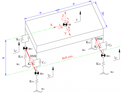
2.1 Spatial dynamics model
The equations describe the oscillation of the vehicle with 7 degrees of freedom in space as below (Figure 3):
$\begin{align} & m\ddot{z}={{F}_{C11}}+{{F}_{K11}}+{{F}_{C12}}+{{F}_{K12}} +{{F}_{C21}}+{{F}_{K21}}+{{F}_{C22}}+{{F}_{K22}} \\ \end{align}$ (1)
$\begin{align} & \left( {{I}_{x}}+m{{h}^{2}} \right)\ddot{\varphi }=\left( {{F}_{C11}}+{{F}_{K11}}-{{F}_{C12}}-{{F}_{K12}} \right){{t}_{w1}} +\left( {{F}_{C21}}+{{F}_{K21}}-{{F}_{C22}}-{{F}_{K22}} \right){{t}_{w2}}+\left( gsin\varphi +{{a}_{y}}cos\varphi \right)mh \\ \end{align}$ (2)
$\begin{align} & \left( {{I}_{y}}+m{{h}_{1}}^{2} \right)\ddot{\theta }=\left( {{F}_{C11}}+{{F}_{K11}}+{{F}_{C12}}+{{F}_{K12}} \right){{a}_{1}}- \left( {{F}_{C21}}+{{F}_{K21}}+{{F}_{C22}}+{{F}_{K22}} \right){{a}_{2}} \\ \end{align}$ (3)
${{m}_{11}}{{\ddot{\xi }}_{11}}={{F}_{KT11}}-{{F}_{C11}}-{{F}_{K11}}-{{F}_{SB1}}$ (4)
${{m}_{12}}{{\ddot{\xi }}_{12}}={{F}_{KT12}}-{{F}_{C12}}-{{F}_{K12}}+{{F}_{SB1}}$ (5)
${{m}_{21}}{{\ddot{\xi }}_{21}}={{F}_{KT21}}-{{F}_{C21}}-{{F}_{K21}}-{{F}_{SB2}}$ (6)
${{m}_{22}}{{\ddot{\xi }}_{22}}={{F}_{KT22}}-{{F}_{C22}}-{{F}_{K22}}+{{F}_{SB2}}$ (7)
Figure 3. Spatial dynamic model (7DOF)
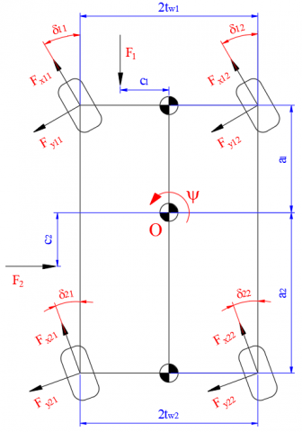
2.2 Nonlinear double-track dynamics model
The equations describe the motion of the vehicle (Figure 4) is as follows [33]:
$\begin{align} & M\left[ {{{\dot{v}}}_{x}}-\left( \dot{\alpha }+\dot{\psi } \right){{v}_{y}} \right] =\sum\limits_{i,j=1}^{2}{\left( {{F}_{xij}}cos{{\delta }_{ij}}-{{F}_{yij}}sin{{\delta }_{ij}} \right)-{{F}_{1}}} \\ \end{align}$ (8)
$\begin{align} & M\left[ {{{\dot{v}}}_{y}}+\left( \dot{\alpha }+\dot{\psi } \right){{v}_{x}} \right] =\sum\limits_{i,j=1}^{2}{\left( {{F}_{xij}}sin{{\delta }_{ij}}+{{F}_{yij}}cos{{\delta }_{ij}} \right)-{{F}_{2}}} \\ \end{align}$ (9)
${{I}_{Z}}\ddot{\psi }=\sum\limits_{i,j=1}^{2}{\left[ \begin{align} & {{\left( -1 \right)}^{j}}\left( {{F}_{xij}}cos{{\delta }_{ij}}-{{F}_{yij}}sin{{\delta }_{ij}} \right){{t}_{wi}}+ {{\left( -1 \right)}^{i+1}}\left( {{F}_{xij}}sin{{\delta }_{ij}}+{{F}_{yij}}cos{{\delta }_{ij}} \right){{a}_{i}} \\ & +{{F}_{i}}{{c}_{i}}-{{M}_{Zij}} \\ \end{align} \right]}$ (10)
Figure 4. Nonlinear double-track dynamic model (3DOF)
To achieve accurate results, this paper uses the Pacejka nonlinear tire model:
$F_{x}=D_{x} \sin \left(\begin{array}{l}C_{x} \arctan \\ {\left[\begin{array}{l}B_{x}\left(1-E_{x}\right)\left(s_{x}+S_{h x}\right)+ \\ E_{x} \arctan \left\{B_{x}\left(s_{x}+S_{h x}\right)\right\}\end{array}\right]}\end{array}\right)+S_{v x}$ (11)
$F_{y}=D_{y} \sin \left(\begin{array}{l}C_{y} \text { arctan } \\ {\left[\begin{array}{l}B_{y}\left(1-E_{y}\right)\left(\alpha+S_{h y}\right)+ \\ E_{y} \arctan \left\{B_{y}\left(\alpha+S_{h y}\right)\right\}\end{array}\right]}\end{array}\right]+S_{v y}$ (12)
$M_{z}=D_{z} \sin \left(\begin{array}{l}C_{z} \arctan \\ {\left[\begin{array}{l}B_{z}\left(1-E_{z}\right)\left(\alpha+S_{h z}\right)+ \\ E_{z} \arctan \left\{B_{z}\left(\alpha+S_{h z}\right)\right\}\end{array}\right]}\end{array}\right]+S_{v z}$ (13)
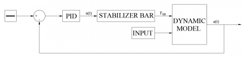
3.1 Establishing the control model
For the hydraulic stabilizer bar, actuators are controlled based on the input voltage signal. Let X is the valve displacement, Eq. (14) describes the dependence between the displacement of the valve and the input voltage u(t):
$\dot{X}+\frac{X}{\tau }-\frac{{{K}_{v}}}{\tau }u=0$ (14)
When the voltage is provided, the valve will open. At this time, hydraulic oil inside the system will follow the line to flow into the motor and exit through the return line. The movement of fluid flow will rotate the motor, producing torque at the motor output. Let qm is the rotation angle of the motor shaft and DP is the pressure difference inside the system. The equation describes the relationship between X, qm, and DP has the following form:
${{K}_{qi}}X-{{D}_{m}}{{\dot{\theta }}_{m}}-{{K}_{ce}}\Delta P-\frac{{{V}_{t}}}{4{{\beta }_{e}}}\Delta \dot{P}=0$ (15)
Assuming that MR is the resistant moment on the motor shaft, this moment is caused by the difference in the load on either side of the wheel (which causes the vehicle to rollover). The equation for the equilibrium of torque at the motor shaft is written as:
${{D}_{m}}\Delta P-{{J}_{m}}{{\ddot{\theta }}_{m}}-{{M}_{R}}=0$ (16)
This research uses the PID controller as shown in Figure 5 The feedback signal e(t) is the displacement of the un-sprung mass, the value of e(t) will be compared with the desired threshold. Through the PID controller, the voltage signal u(t) is sent to the actuator of the stabilizer bar. Therefore, the hydraulic motor will generate the torque, which corresponds to the force of the stabilizer bar acting on the wheels (FSB). The remaining Input values of the model are the parameters of the established model.
Figure 5. PID Controller schematic
3.2 Simulation conditions
The oscillation of the vehicle is simulated in 2 cases, for each case, there will be different velocity values:
+ Case 1: J-turn Steering (Figure 6).
+ Case 2: Fish-hook Steering (Figure 7).
The results of the simulation respectively to 3 conditions:
+ Condition 1: The vehicle isn't equipped with the stabilizer bar (NSB).
+ Condition 2: The vehicle is equipped with the mechanical stabilizer bar (MSB).
+ Condition 3: The vehicle is equipped with the hydraulic stabilizer bar (HSB).
Figure 6. J-turn steering
Figure 7. Fish-hook steering
The coefficients used in the above 3 equations are given in Table 1.
Table 1. Reference coefficients
|
Symbol |
Description |
Value |
Unit |
|
t |
Time constant of the servo-valve |
0.005 |
s |
|
Kv |
Servo valve gain |
0.025 |
m/A |
|
Kqi |
Valve flow gain coefficient |
0.02 |
m2/s |
|
Kce |
Total flow pressure coefficient |
4´10-11 |
m5/(Ns) |
|
Vt |
Total volume of trapped oil |
10-3 |
m3 |
|
$\beta_{\mathrm{e}}$ |
Effective bulk modulus of the oil |
6´106 |
N/m2 |
|
Jm |
Moment of inertia of the hydraulic motor |
2 |
kgm2 |
|
Dm |
Flow rate per revolution |
1.6´10-5 |
m3/rad |
The reference parameters of the vehicle are given in Table 2.
Table 2. Reference parameters
|
Symbol |
Description |
Value |
Unit |
|
a1 |
The distance from the center of gravity to front axle |
1.25 |
m |
|
a2 |
The distance from the center of gravity to rear axle |
1.65 |
m |
|
tw1 |
The half of track width of the front axle |
0.725 |
m |
|
tw2 |
The half of track width of the rear axle |
0.720 |
m |
|
m |
Sprung mass |
1650 |
kg |
|
mij |
Un-sprung mass |
50 |
kg |
|
h |
The distance from center of gravity to roll axis |
0.5 |
m |
|
Ix |
Moment of inertia of the x-axis |
650 |
kgm2 |
|
Iy |
Moment of inertia of the y-axis |
2500 |
kgm2 |
|
Iz |
Moment of inertia of the z-axis |
2500 |
kgm2 |
|
g |
Gravity acceleration |
9.81 |
m/s2 |
4.1 J-turn steering
At the value v1 = 60 (km/h)
When the vehicle moves at a speed v1 = 60 (km/h), the values of the roll angle of the vehicle j, displacement of the un-sprung mass xij, and vertical force Fzij are given as in Figure 8, Figure 9, and Figure 10.
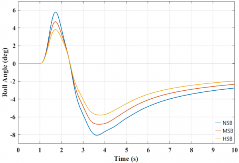
Figure 8. The roll angle of the vehicle
In this case, the value of the roll angle j was reduced from 5.55° (non-stabilizer bar) to 4.69° (mechanical stabilizer bar) and 3.98° (hydraulic stabilizer bar).
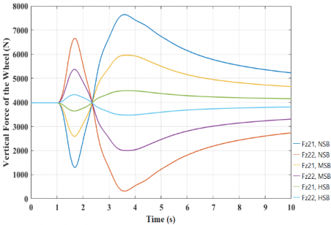
Normally, when the vehicle steers, the rear wheel tends to lift off the road more than the front wheel. Therefore, simulations of displacement of the un-sprung mass xij and vertical force Fzij are conducted at the rear wheel. The graph in Figure 9 shows a very large difference in the displacement of the un-sprung mass xij at v1 = 60 (km/h). These values are respectively 18.15 (mm), 9.97 (mm), and 1.86 (mm) corresponding to the above 3 conditions.
The value of the vertical force Fzij also varies greatly when the vehicle is equipped with the mechanical stabilizer bar and the hydraulic stabilizer bar (Figure 10). Therefore, the stabilizer bar can support the vehicle to move more stably and safely in dangerous conditions.
Figure 9. The displacement of the un-sprung mass
Figure 10. The vertical force at the wheel
At the value v2 = 90 (km/h)
Figure 11. The roll angle of the vehicle
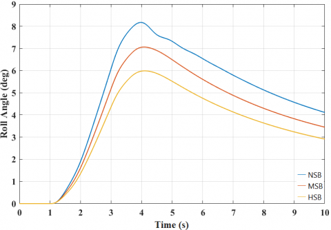
If the vehicle speed increases to v2 = 90 (km/h), the difference in simulation values changes greatly. Figure 11 shows the value of the roll angle of the vehicle j in 3 simulation conditions. These values significantly reduced from 8.23° to 7.08° and 6.01° respectively.
Figure 12. The displacement of the un-sprung mass
Figure 13. The vertical force at the wheel
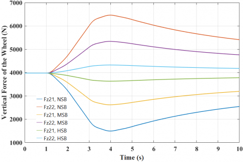
The value of the displacement of the un-sprung mass $\xi_{\mathrm{ij}}$ also varies significantly, about 28.12 (mm) and 3.74 (mm) in the case of the vehicle isn't equipped with the stabilizer bar and the vehicle is equipped with the hydraulic stabilizer bar (Figure 12). The graph of Figure 13 shows the vertical force difference at the wheel. When this value decreases to "0", the wheel will lift off the road surface, the phenomenon of the rollover may occur. If the vehicle isn't equipped with the stabilizer bar, the value of Fz22 will reach 305 (N). When the vehicle is equipped with the mechanical stabilizer bar, the value of Fz22 increases to 1990 (N), which is a safe level. However, if the mechanical stabilizer bar is replaced by the hydraulic stabilizer bar, this value reaches 3490 (N). Therefore, the vehicle that uses the hydraulic stabilizer bar can improve safety and stability when steering at high speeds.
4.2 Fish-hook steering
The case of the J-Turn steering is usually less dangerous than the case of Fish-hook steering. The results below describe the simulation values in case of dangerous steering.
At the value v1 = 60 (km/h)
In this case, the roll angle of the vehicle (Figure 14) reached great value. If the vehicle isn't equipped with the stabilizer bar, this value is about 8°. If the vehicle is equipped with the mechanical stabilizer bar or the hydraulic stabilizer bar, this value drops to 7.45° and 5.90°.
Figure 14. The roll angle of the vehicle
Figure 15. The displacement of the un-sprung mass
Figure 16. The vertical force of the wheel
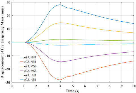
Besides, the value of the displacement of the un-sprung mass $\xi_{\mathrm{ij}}$ also changed quite a lot (Figure 15). These values are respectively 27.96 (mm), 14.35 (mm), and 3.06 (mm) corresponding to 3 simulated conditions.
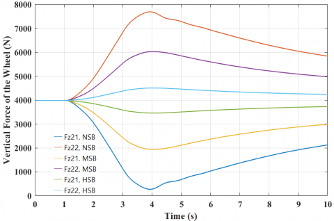
Graphs Figure 16 shows the change of the vertical force Fzij in the rear wheels. If the vehicle is not equipped with the stabilizer bar, the value of Fz22 reaches 385 (N), the phenomenon of wheel separation from the road surface can occur. If the vehicle is equipped with the mechanical stabilizer bar or the hydraulic stabilizer bar, this value can greatly increase, 2002 (N), and 3523 (N) respectively.
At the value v2 = 90 (km/h)
When the speed of the vehicle increases to 90 (km/h), the danger signs would have occurred if the vehicle isn't equipped with the stabilizer bar.
Figure 17. The roll angle of the vehicle
Figure 18. The displacement of the un-sprung mass
Figure 19. The vertical force of the wheel
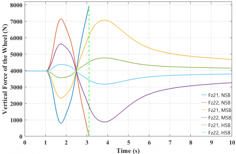
Graph Figure 17 shows the value of the roll angle of the vehicle j at v2 = 90 (km/h). At this time, if the vehicle isn't equipped with the stabilizer bar, the vehicle will be rollover at time t = 3.11 (s). If the vehicle is equipped with the stabilizer bar, it can move more safely and steadily. The value of the displacement of the un-sprung mass also tends to change similarly (Figure 18).
The change of vertical force at the wheel is clearly shown in Figure 19. At the same time (t = 3.11 s), the value of Fz22 was reduced to "0", the wheel was lifted off the road completely, the phenomenon of the rollover occurred [34]. If the vehicle is equipped with the mechanical stabilizer bar, this value is 905 (N). However, this is still a dangerous threshold, it does not guarantee stability and safety. If the vehicle uses the hydraulic stabilizer bar, the value of the vertical force Fz22 reaches 3225 (N), which is a safe limit for vehicles on the move.
The content of the paper focuses on researching the control model of the active stabilizer bar is equipped with the vehicle. This paper has established the vehicle's dynamics model to describe its oscillation. Besides, the active stabilizer bar control method has been introduced and applied in this research. The results of the simulation show that when the vehicle is equipped with the active stabilizer bar, parameters such as the roll angle of the vehicle body, displacement of the un-sprung mass have been significantly reduced.
In dangerous cases (Fish-hook steering, v = 90 km/h), if the vehicle isn't equipped with the stabilizer bar, the vehicle may be rollover (at time t = 3.11 s). When the vehicle is equipped with the mechanical stabilizer bar, this phenomenon may not occur. However, the vehicle is still not stable and safe. If the speed of the vehicle continues to increase, the vehicle will still be rollover despite using the mechanical stabilizer bar.
The solution to improve stability and safety in dangerous cases is using the hydraulic stabilizer bar. The hydraulic stabilizer bar can generate a much larger torque than the conventional mechanical stabilizer bar. Therefore, the phenomenon of rollover can be significantly improved. The vertical force difference of the wheels is very small, the wheels are still on the road. At the same time, the roll angle of the vehicle and the displacement of the un-sprung mass is also quite small. The results of this research have shown the outstanding advantages of the hydraulic stabilizer bar compared to the conventional mechanical stabilizer bar. The PID controller is used in this paper is completely suitable with the established model. However, this model needs to be verified by experiment. In the future, to improve the stability and safety of the vehicle when moving, there are a lot of integrated control methods can be applied based on the model established in this paper. The results of the paper will be the basis for other more complex studies.
|
ai |
The distance from the center of gravity to front/rear axle, m |
|
ay |
Lateral acceleration, m/s2 |
|
ci |
The distance from the center of gravity to the place of external force, m |
|
FCi |
Restrict force of the damper, N |
|
Fi |
External force, N |
|
FKij |
Elastic force of the spring, N |
|
FKTij |
Elastic force of the tire, N |
|
FSBi |
Force of the stabilizer bar, N |
|
Fxij |
Longitudinal force of the wheel, N |
|
Fyij |
Lateral force of the wheel, N |
|
Fzij |
Vertical force of the wheel, N |
|
h |
The distance from the center of gravity to roll axis, m |
|
Ix |
Moment of inertia of the x-axis, kgm2 |
|
Iy |
Moment of inertia of the y-axis, kgm2 |
|
Iz |
Moment of inertia of the z-axis, kgm2 |
|
m |
Sprung mass, kg |
|
M |
Total mass, kg |
|
mij |
Un-sprung mass, kg |
|
Mzij |
Moment of the wheel, Nm |
|
twi |
The half of the track width of the front/rear axle, m |
|
uij |
Bump on the road, m |
|
vx |
Longitudinal velocity, m/s |
|
vy |
Lateral velocity, m/s |
|
z |
Vertical displacements of the sprung mass, m |
|
Greek symbols |
|
|
$\theta$ |
Pitch angle, rad |
|
$\psi$ |
Yaw angle, rad |
|
$\varphi$ |
Roll angle, rad |
|
$\delta_{i j}$ |
Steering angle, rad |
|
$\xi_{i j}$ |
Vertical displacements of the un-sprung mass, m |
|
$\alpha$ |
Slip angle, rad |
[1] Khan, M.M., Awan, A.U., Liaquat, M. (2015). Improving vehicle handling and stability under uncertainties using probabilistic approach. Proceedings of the International Federation of Automatic Control, Zurich, pp. 242-247. http://dx.doi.org/10.1016/j.ifacol.2015.11.094
[2] Tuljapure, S.B., Kanna, L.S. (2013). Analysis on stabilizer bar. International Journal of Advanced Materials Manufacturing and Characterization, 3(1): 349-354. http://dx.doi.org/10.11127/ijammc.2013.02.064
[3] Nikhil, K., Daspute, D.H. (2018). Dynamic analysis of anti-roll bar. Materials Today, 5(5): 12490-12498. http://dx.doi.org/10.1016/j.matpr.2018.02.230
[4] Li, Z.X., Xu, R.Z., Jiang, H. (2016). Roll stiffness optimization for anti-roll bar in interconnected air suspension. Journal of Applied Science and Engineering, 19(3): 293-302. http://dx.doi.org/10.6180/jase.2016.19.3.07
[5] Bayrakceken, H., Tasgentiren, S., Aslantas, K. (2006). Fracture of an automobile Anti-roll Bar. Engineering Failure Analysis, 13(5): 732-738. http://dx.doi.org/10.1016/j.engfailanal.2005.04.002
[6] Nguyen, T.A., Hoang, T.B. (2019). Research on determining the limited roll angle of vehicle. Proceedings of the International Conference Engineering Research and Application, Thainguyen, Vietnam, pp. 613-619. http://dx.doi.org/10.1007/978-3-030-37497-6_70
[7] Rydberg, K.E. (2016). Hydraulic Servo Systems: Dynamic Properties and Control. Linkoping: Linkoping University Electronic Press.
[8] Moshchuk, N., Chen, S.K. (2019). Vehicle rollover detection index. Proceedings of the International Mechanical Engineering Congress and Exposition, Florida, USA, pp. 583-587. http://dx.doi.org/10.1115/IMECE2009-10142
[9] Rajamani, R., Piyabongkarn, D., Tsourapas, V., Lew, J.Y. (2011). Parameter and state estimation in vehicle roll dynamics. IEEE Transactions on Intelligent Transportation Systems, 12(4): 1558-1567. http://dx.doi.org/10.1109/TITS.2011.2164246
[10] Phanomchoeng, G., Rajamani, R. (2011). New rollover index for detection of tripped and un-tripped rollovers. Proceedings of the 50th IEEE Conference on Decision and Control and European Control Conference (CDC-ECC), Florida, USA, pp. 7440-7445. http://dx.doi.org/10.1109/CDC.2011.6160823
[11] Xiong, F., Lan, F., Chen, J., Zhou, Y. (2015). The study for anti-rollover performance based on fish-hook and j-turn simulation. Proceedings of the 3rd International Conference on Material and Manufacturing Engineering, Guangzhou, China, pp. 2084-2093. http://dx.doi.org/10.2991/ic3me-15.2015.401
[12] Parczewski, K., Wnek, H. (2017). The influence of vehicle body roll angle on the motion stability and maneuverability of the vehicle. Combustion Engines, 168(1): 133-139. http://dx.doi.org/10.19206/CE-2017-121
[13] Wu, X., Ge, X., Luo, S., Huang, H. (2010). Research on vehicle rollover and control. Proceedings of the 2010 2nd International Conference on Advanced Computer Control, Shenyang, China, pp. 510-514. http://dx.doi.org/10.1109/ICACC.2010.5486695
[14] Li, B., Bei, S. (2019). Research method of vehicle rollover mechanism under critical instability condition. Advances in Mechanical Engineering, 11(1): 1-11. http://dx.doi.org/10.1177/1687814018821218
[15] Nguyen, T.A., Hoang, T.B. (2019). Research on dynamic vehicle model equipped active stabilizer bar. Advances in Science, Technology, and Engineering Systems Journal, 4(4): 271-275. http://dx.doi.org/10.25046/aj040434
[16] Vu, V.T., Saname, O., Dugard, L., Gaspar, P. (2016). H∞ active anti-roll bar control to prevent rollover of heavy vehicles: A robustness analysis. Proceedings of the International Federation of Automatic Control, Istanbul, Turkey, pp. 99-104. http://dx.doi.org/10.1016/j.ifacol.2016.07.503
[17] Vu, V.T., Sename, O., Dugard, L., Gaspar, P. (2016). Active anti-roll bar control using electronic servo valve hydraulic damper on single unit heavy vehicle. Proceedings of the International Federation of Automatic Control, Istanbul, Turkey, pp. 418-425. http://dx.doi.org/10.1016/j.ifacol.2016.08.062
[18] Vu, V.T., Sename, O., Dugard, L., Gaspar, P. (2019). H∞ / LPV controller design for an active anti-roll bar system of heavy vehicles using parameter dependent weighting functions. Heliyon, 5(6): 1-11. http://dx.doi.org/10.1016/j.heliyon.2019.e01827
[19] Vu, V.T. (2017). Enhancing the roll stability of heavy vehicles by using an active anti-roll bar system. Ph.D. dissertation, Communication University Grenoble Alpes, France.
[20] Varga, B., Nemeth, B., Gaspar, P. (2015). Design of anti-roll bar systems based on hierarchical control. Journal of Mechanical Engineering, 61(6): 374-382. http://dx.doi.org/10.5545/sv-jme.2014.2224
[21] Varga, B., Nemeth, B., Gaspar, P. (2013). Control design of anti-roll bar actuator based on constrained LQ method. Proceedings of the 14th International Symposium on Computational Intelligence and Informatics, Budapest, Turkey, pp. 31-36. http://dx.doi.org/10.1109/CINTI.2013.6705219
[22] Zulkarnain, N., Zamzuri, H., Mazlan, S.A. (2014). Ride and handling analysis for an active Anti-roll Bar: Case study on composite nonlinear control strategy. International Journal of Automotive and Mechanical Engineering, 10(2): 2122-2143. http://dx.doi.org/10.15282/ijame.10.2014.28.0179
[23] Zulkarnain, N., Imaduddin, F., Zamzuri, H., Mazlan, S.A. (2012). Application of an active anti-roll bar system for enhancing vehicle ride and handling. Proceedings of the 2012 IEEE Colloquium on Humanities, Science, and Engineering, Kota Kinabalu, Malaysia, pp. 260-265. http://dx.doi.org/10.1109/CHUSER.2012.6504321
[24] Zulkarnain, N., Zamzuri, H., Mazlan, S.A. (2014). LQG control design for vehicle active anti-roll bar system. Applied Mechanics and Materials, 663: 146-151. http://dx.doi.org/10.4028/www.scientific.net/AMM.663.146
[25] Muniandy, V., Samin, P.M., Jamaluddin, H., Radman, R.A., Bakar, S.A.A. (2017). Double anti-roll bar hardware-in-loop experiment for active anti-roll control system. Journal of Vibroengineering, 19(4): 2886-2909. http://dx.doi.org/10.21595/jve.2016.17045
[26] Krid, M., Benamar, F. (2011). Design and control of an active anti-roll system for a fast rover. Proceedings of the 2011 IEEE International Conference on Intelligent Robots and Systems, California, USA, pp. 274-279. http://dx.doi.org/10.1109/IROS.2011.6094963
[27] Michael, D. (2013). Design and development of a composite automotive anti-roll bar. Master dissertation. University of Windsor, Canada.
[28] Mariappa, A.P.P. (2018). Design, and optimization of anti-roll bar. Master dissertation. Kaunas University of Technology, Litva.
[29] Agrawal, H., Gustafsson, J. (2017). Investigation of active anti-roll bars and development of control algorithm. Master dissertation. Chalmers University of Technology, Sweden.
[30] Zulkarnain, N., Hussain, A., Zamzuri, H., Mokri, S.S. (2019). Controller design for an active anti-roll bar system. Proceedings of the 14th IEEE Conference on Industrial Electronics and Applications, Xian, China, pp. 2213-2217. http://dx.doi.org/10.1109/ICIEA.2019.8834106
[31] Zulkarnain, N.B., Zamzuri, H., Mustafa, M.M., Mokri, S.S., Wahid, N., Ahmmad, S.N.Z., Jedi, A. (2018). Newly developed nonlinear vehicle model for an active anti-roll bar system. Bulletin of Electrical Engineering and Informatics, 7(4): 529-537. http://dx.doi.org/10.11591/eei.v7i4.1185
[32] Brisson, S.G., Bouazara, M., Richard, M.J. (2009). Design of an active anti-roll bar for off-road vehicles. Shock and Vibration, 16: 155-174. http://dx.doi.org/10.3233/SAV-2009-0459
[33] Nguyen, T.A. (2020). Establishing the dynamics model of the vehicle using the 4-wheels steering systems. Mathematical Modelling of Engineering Problems, 7(3): 436-440. https://doi.org/10.18280/mmep.070314
[34] Nguyen, T.A., Hoang, T.B. (2020). Determining the vertical force when steering. Advances in Systems Science and Applications, 20(4): 27-35. https://doi.org/10.25728/assa.2020.20.4.870