Arnab Bose | Prabhakar Sathujoda*
© 2020 IIETA. This article is published by IIETA and is licensed under the CC BY 4.0 license (http://creativecommons.org/licenses/by/4.0/).
OPEN ACCESS
The study aims to investigate the vibration characteristics of ceramic-based functionally graded materials (FGM) when subjected to dynamic conditions. Effect of thermal gradients on natural frequencies of rotating FG shafts has been investigated using three dimensional (3D) solid elements which is rarely found in literature. The FG material used in the work has metal and ceramic as its constituents. Three-dimensional finite element modelling and analysis of the FG shaft system has been carried out using ANSYS software to determine the natural frequencies with proper validations. The study involves modelling of the shaft using two different material laws; power-law and exponential law. Continuous variation of material properties is achieved using a Python code that discretizes the shaft radially and applies the position-dependent material properties. The shaft has been subjected to different thermal environments by applying temperature gradients accordingly. Thermal gradation is achieved using two different methods, nonlinear temperature distribution (NLTD) and exponential temperature distribution (ETD). Effects of material gradation on the fundamental frequencies of the shaft is presented. The variations due to different material laws and thermal gradients are also identified. The whirl frequencies have been determined for the rotating shaft system. The effect of material gradation laws and temperature gradients on separation of the frequencies at rotating speeds is determined. Attempts have been made to obtain suitable reasons for the behaviours based on the material properties. The obtained results show the influence of material gradation methods, power-law index, and temperature gradients on vibration characteristics of the ceramic-based FG shaft system. Furthermore, the reasons of the variations are also discussed in detail.
functionally graded material, non-linear temperature distribution, exponential temperature distribution, finite element method, whirl frequencies
Vibration characteristics of rotor systems have been a topic of interest among engineers and researchers for a long time. Material properties and dynamic characteristics are critical factors while designing any rotating machinery. Advancements in the development of new materials to improve structural performance have been a challenge. Rotor systems made of composites have several advantages when compared to metallic rotor shafts such as increased stiffness to weight ratio, higher specific strength, and specific stiffness. For these reasons, composite rotor shafts are preferred for certain applications in aerospace, automobile, sensor and energy conservation, biomedical fields. However, at higher temperatures, traditional composites have specific issues such as debonding, which occurs when the physical, chemical, and mechanical bonds holding the adhesive to the substrate breaks. Delamination which is the separation of laminated materials and residual stresses, are some more factors that restrict the usage of these traditional composites. Although ceramics exhibit significant resistance to temperature, they have limited application due to low toughness and brittle nature. Such problems can be overcome by the development of functionally graded materials (FGM) that have enhanced properties and applications. A typical FGM is an advanced composite, which is obtained by inhomogeneous mixing of different phases of materials. Metals and ceramics usually form the constituent elements used to manufacture FGM. The volume fraction of both these constituents is gradually varied based on different material laws, which result in smooth and gradual variation in mechanical properties. Rotor dynamics lays the foundation of the current work. Some of the essential works in this direction are presented in the following paragraph.
Dimentberg [1] studies were based on viscous and hysteretic internal damping of a rotating shaft and his works pointed out that viscous damping is destabilizing at speeds beyond the first critical, and hysteretic damping is destabilizing at all speeds. Ruhl and Booker [2] developed a finite element method (FEM) for modeling the rotor system by considering the effects of translational inertia and bending. Lund [3] described a method for calculating the threshold speed of instability and the critical speeds of a general, flexible rotor in fluid-film journal bearings. Zori and Nelson [4] study extend the linear finite element concept to provide a detailed evaluation of damped rotor stability. In this work, the effects of both internal viscous and hysteretic damping have been incorporated into the finite element model. Nelson and Mcvaugh [5] presented a procedure for dynamic modeling of rotor-bearing systems, which consist of rigid disks, distributed parameter finite rotor elements, and discrete bearings. Another work by Nelson [6] included the study of the effects of rotatory inertia, gyroscopic moments, axial load, and internal damping; but have not included shear deformation or axial torque effects. Ozgiiven and Ozkan [7] work considered rotary inertia, gyroscopic moment, axial load, internal viscous and hysteretic damping and transverse shear deformations all in the same model. Previous works [1-7] are based on shaft systems modeled using isotropic materials.
Early application of gradation laws for composites was proposed in works of Bever and Duwez [8], and Shen and Bever [9] in 1972, but the work had limited impact due to restrictions in the knowledge of FGM production techniques. The first practical application of FGMs was carried out by Japanese material scientists at National Aerospace Laboratory of Japan in 1984 to prepare advanced ultra-high temperature resistance structural materials for using not only in space structures, fusion reactors, and future space-plane system but also in various functional (optic and electronic) materials [10]. Sankar provided an elasticity solution for FG beams using exponential law [11]. Chakraborty et al. [12], based on the theory of first-order shear deformation (FOSD), proposed a two noded beam element for FGMs and applied it to static, thermal, and free vibrations problems. Using a multi-layered approach for FG circular hollow shaft, Shao [13] calculates the analytical solution for thermal and mechanical loads. Laminated FG beam under thermal-induced initial stresses was analyzed for free and forced vibrations by Xiang et al. [14]. Reddy and Chin [15] studied the dynamic thermoelastic response of functionally graded cylinders and plates using finite element modeling and considering the effect of thermomechanical coupling in the formulation. Shahba et al. [16] developed free vibration and stability analysis of axially FG homogeneous tapered Timoshenko beams based on the FE approach. Gayen and Roy [17] work deal with the study of vibration and stability analysis of a functionally graded spinning shaft system using a three-noded beam element based on the Timoshenko beam theory. Gayen et al. [18, 19] carried out free vibration analysis of functionally graded (FG) non-spinning simply supported shaft having a transverse surface crack and analyzed whirl frequencies and critical speed of the rotor system with transverse crack by FE formulation using two noded Timoshenko beam elements. Recently an attempt has been made by Arnab and Prabhakar [20] on three-dimensional solid modelling of FG rotor systems.
Although a lot of work has been carried out to understand the vibration characteristics of these ceramic-based composites FG materials, few studies have been performed on the FG shaft system. Also, most of the work in FG systems has been carried out using beam elements. As FGM are finding widespread use in complex systems, analysis using three-dimensional solid elements for accurate modeling of the problems is needed. Thus, the present work aims to study the dynamic characteristics of the ceramic-based FG shaft system, modeled using three-dimensional hex elements by considering two FG material and temperature distribution laws. Two different material gradation laws, namely power-law and exponential law, have been used. The effects of temperature gradients on the properties of the FG material have been studied. The analysis has been performed by varying the metal core temperature (Tm) which is rarely found in previous works on FG shafts. Efforts have been made to understand the impacts of the two temperature distribution methods NLTD and ETD on vibration characteristics of the FG materials.
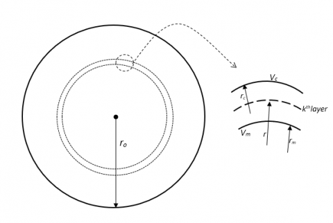
The actual microstructural shapes and gradation of FG material are not available. However, the volume fraction distribution within the FG material can be represented using different mathematical laws. The material properties are varied by varying the distribution of volume fraction with the spatial coordinates. Figure 1 has been taken from the works of Aboudi et al. [21] and shows the continuously graded microstructure of an FG material. For FG shafts, the properties vary radially. A radial variation of volume fraction [17] is shown in Figure 2. The inner core of the shaft purely composed of metal, and the volume fraction of metal decreases, and that of ceramics increases radially outwards. Thus, the outer layer is exclusively made of ceramic, which offers excellent temperature resistance properties. The position dependence is obtained by using the Voigt model, which gives a simple rule for composite materials. The material properties Pi for each layer is expressed as in Eq. (1).
Pi=PcVc+PmVm (1)
where, Pc and Pm are the material properties of ceramic and metal, respectively, and Vc and Vm refer to the volume fraction of ceramic and metal respectively. The sum of both the volume fractions is unity. Several different mathematical models have been developed over the years by researchers to predict the distribution accurately. Power law, exponential law, Sigmoid law and Mori-Tanka scheme are the laws commonly used for the gradation of FG materials. However, most of the previous works are based on the power-law gradation of FG shafts. In the present study power-law and exponential law gradations have been applied to the rotor systems. Modeling using these laws and their application has been discussed in detail in the subsections.
Figure 1. Continuously graded microstructure in cut section of the FG shaft
Apart from radial variation, the properties of FGMs also depend on temperature. In most applications of FG shafts, the outer ceramic is subjected to higher temperatures than the inner metalcore. This difference in gradation generates a radial variation of material properties in the shaft. The temperature-dependent properties have been proposed by Touloukian [22] as in Eq. (2), where P0, P1, P2 and P3 are different material-dependent temperature coefficients. These coefficients are shown in Table 1 and are taken from the work of Reddy et al. [15].
P(T) = P0 (P-1 T-1 + 1 + P1 T1 + P2 T2 + P3T3) (2)
Stainless Steel-Aluminium oxide (SS-Al2O3) is used to model the FG shaft in the present work and the temperature coefficients can be obtained from the works of Reddy et al. [15].
Figure 2. Radial variation of volume fraction
Table 1. Temperature coefficients for constituent materials
|
Material Properties |
C0 |
C-1 |
C1 |
C2 |
C3 |
|
|
Steel |
E |
201.04e9 |
0 |
3.08e-4 |
-6.534e-7 |
0 |
|
K |
15.379 |
0 |
-1.264e-3 |
2.09e-6 |
-3.7e-10 |
|
|
v |
0.3262 |
0 |
-2e-4 |
3.797e-7 |
0 |
|
|
Al2O3 |
E |
349.55e9 |
0 |
-3.85e-4 |
4.02e-7 |
-1.67e-10 |
|
K |
-14.08 |
-1123 |
-6.227e-3 |
0 |
0 |
|
|
v |
0.26 |
0 |
0 |
0 |
0 |
|
The thermomechanical responses of FGM can accurately be modelled by using different temperature distribution methods obtained from the literature. For an axis-symmetric solid cylinder, assuming no heat generation and solving the 1-D Fourier heat conduction equation with suitable boundary conditions as shown in Eq. (3) yields the radial temperature distribution profiles.
$\frac{d}{d r}\left[r K(r) \frac{d T}{d r}\right]=0$ (3)
2.1 Power law distribution with NLTD
The power law is the most commonly used law to achieve the FG material gradation. It is an established model and has been used extensively to model the behaviour of FG plates, shafts, etc. For a circular cross-section FG shaft or cylinder, the position-dependent material properties P(r) can be expressed as in ref. [15] by Eq. (4):
$P(r)=P m+(P c-P m) V o(r), V o(r)=\left(\frac{r-R i}{B \rho-B i}\right)^{k}, R i \leq r \leq R o, 0 \leq k \leq \infty$ (4)
where, P(r) denotes the radially varying material properties such as Young’s Modulus, Poisson’s ratio, Thermal conductivity (K), density, and coefficient of thermal expansion. Pm and Pc are temperature-dependent material properties at the ceramic rich and metal-rich region, respectively. These are obtained by solving Eq. (3) at respective metal and ceramic temperatures. Ro and Ri are the outer and inner radii of the cylinder, respectively. ' k' is the power-law index. The volume fraction of metal, at a mid-radius 'r 'of any layer is represented by Vo(r).
NLTD has been studied in several research works on FGMs and is used with power-law gradation. It is the solution to Eq. (3) subjected to mentioned boundary conditions and considering the first seven terms of the polynomial expansion [23] gives Eq. (5):
$T(r)=T m+(T c-T m)\left[\sum_{j=0}^{5}\left\{\frac{(-1)^{j}}{j k+1}\left(\frac{K c m}{K m}\right)^{j}\left(\frac{r-R i}{R o-R i}\right)^{j k+1}\right\}\right] /\left[\sum_{j=0}^{5} \frac{(-1)^{j}}{j k+1}\left(\frac{K c m}{K m}\right)^{j}\right]$ (5)
where, Kcm = Kc – Km. Kc and Km refer to the thermal conductivity of ceramic rich and metal-rich regions at a given temperature. Kc and Km are temperature dependent and are also calculated using Eq. (4) at respective metal and ceramic temperatures.
2.2 Modelling using exponential law gradation with ETD
Several researchers have used exponential law for FG plates, disks and shells, but works on FG shafts are very scarce. The position-dependent material properties using exponential law for a circular cross-section FG shaft can be given as [24] shown in Eq. (6):
$P(r)=\operatorname{Pm} \exp \{\lambda(r-R i)\}, \quad$ where $\lambda=\left(\frac{\ln \left(\frac{P c}{P m}\right)}{R o-R i}\right), \quad R i \leq r \leq R o$ (6)
P(r) denotes the position-dependent material properties. Pc and Pm are properties of the ceramic rich and metal-rich region, respectively. This law governs all the material property distributions except for Poissons’s ratio. Poissons’s ratio is kept constant under exponential law.
Exponential temperature distribution (ETD) is used to estimate the temperature distribution profile with exponential law. The ETD is obtained using the thermal conductivity equation for cylinders with appropriate boundary conditions. Eq. (7) can be used to obtain the temperature distribution along cross-section 0f the shaft [10].
$T(r)=A+B e^{-\lambda(r-R i)}, \quad R i \leq r \leq R o$ (7)
where,
$A=T m-\frac{(T c-T m)}{e^{-\lambda(R o-R i)-1}}, B=\frac{(T c-T m)}{e^{-\lambda(R o-R i)-1}}, \lambda=\left(\frac{\ln \left(\frac{K c}{K m}\right)}{R o-R i}\right)$
T(r) is the temperature value at radial distance 'r', and Tc and Tm are temperatures at the ceramic rich and metal-rich regions. Pm and Pc refer to the position-dependent material properties at the ceramic rich and metal-rich area, respectively. The following temperature distribution law can be used for the analysis of shafts, where exponential gradation is desired.
2.3 Modelling in present work
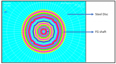
The FG rotor is composed of SS-Al2O3. The mechanical properties of the individual constituents of these FG materials have been shown in Table 2. The FG rotor is divided into twenty layers radially to estimate the continuous material distribution. The radial division is selected based on convergence study during validation with literature, however more number of layers can be assigned by the code based on computational ability. A Python code has been developed to generate ANSYS macros that contain the desired material distribution. The user can give input for the dimensions of the rotor, choice of material distribution law, temperature distribution and the size of each layer. Using this information, the material properties are assigned to each segment by calculating its value at the layer mid-radius. The output is generated in the form of macros, which can be imported in ANSYS to achieve the gradation. Figure 3 shows the layer-wise material variation present in the SS-Al2O3 FG shaft modelled using ANSYS.
Table 2. Mechanical properties of constituent materials of FGMs at different temperatures
|
$\Delta \mathbf{T}$ (K) |
Material Properties |
Stainless Steel |
Aluminium oxide (Al2O3) |
|
300 |
Young’s Modulus (GPa) |
210 |
390 |
|
Density (Kg/m3) |
7800 |
3960 |
|
|
Poisson’s Ratio |
0.3 |
0.26 |
|
|
600 |
Young’s Modulus (GPa) |
190.89 |
306.78 |
|
Density (Kg/m3) |
7800 |
3960 |
|
|
Poisson’s Ratio |
0.331 |
0.26 |
|
|
900 |
Young’s Modulus (GPa) |
150.34 |
299.72 |
|
Density (Kg/m3) |
7800 |
3960 |
|
|
Poisson’s Ratio |
0.367 |
0.26 |
|
|
1200 |
Young’s Modulus (GPa) |
86.16 |
289.57 |
|
Density (Kg/m3) |
7800 |
3960 |
|
|
Poisson’s Ratio |
0.426 |
0.26 |
Figure 3. Material gradation in SS-Al2O3 shaft modelled using ANSYS
However, for more accurate assignment of the density, each layer is assigned the layer average density. The density function is taken to vary as power-law or exponential law and is averaged over the inner radius to the outer radius of the layer. The equations Eq. (8) and Eq. (9) show the averaged density equations for power law and exponential law, respectively, where $\rho c$ and $\rho m$ are the densities of metal and ceramic used. These equations give a more uniform density variation than directly applying mid-radius density to the layer. Here, r1 and r2 refer to the internal and external radius of the selected layer.
$\rho \mathrm{avg}=\frac{\int_{r 1}^{r 2}\left[(\rho \mathrm{c}-\rho \mathrm{m})\left(\frac{r-R i}{R o-R i}\right)^{k}+\rho \mathrm{m}\right] d r}{\int_{r 1}^{r 2} d r}$ (8)
$\rho \operatorname{avg}=\frac{\int_{r_{1}}^{r_{2}}[(\rho m) \exp \{\lambda(r-R i)\}] d r}{\int_{r_{1}}^{r_{2}} d r},$ where $\lambda=\left(\frac{\ln \left(\frac{\rho c}{\rho m}\right)}{R o-R i}\right)$ (9)
ANSYS software has been used to carry out finite element modelling and analysis of the shaft system. The detailed description of the shaft system dimensions, modelling, meshing strategies and loads and boundary conditions are discussed in subsections 3.1 to 3.3.
3.1 Modelling in present work
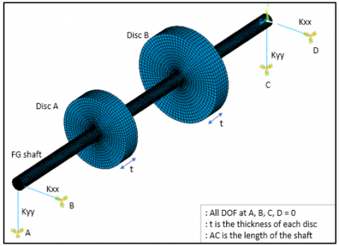
A double-disc rotor system shown in Figure 4 has been used to study its vibration characteristics. The rotor system geometry is adopted from the reference Friswell et al. [25]. The shaft has a length of 1.5 m and has a diameter of 0.05 m. The discs are mounted on a shaft at a distance of 0.5 m and 1 m from one end of the shaft. Disc A has a diameter of 0.28 m and is 0.07 m thick. Disc B is 0.07 m thick with a diameter of 0.35. The shaft has no internal damping effects and is supported on identical isotropic bearings at its ends. These bearings have a stiffness of 1MN/m in both x (Kxx) and y (Kyy) directions. The effects of damping and cross-coupling are not considered in these bearings
Figure 4. ANSYS model of the double-disc shaft on bearing support
3.2 Analytical model
The finite element modelling of the shaft has been carried out in ANSYS software using three dimensional solid elements. The detailed description of each element type used in the modelling can be obtained from the ANSYS manual [26]. SOLID-185 element is used to model the shafts and discs. SOLID-185 elements have eight nodes, and each node has three degrees of freedom, translational in x, y, and z directions. These elements are used to achieve a mapped meshing of the shaft and the discs. The shaft is discretised into twenty layers along the radial direction to apply the material gradation properties. Meshing produced no warning elements, and the connectivity of elements has been checked. The position-dependent material properties can now be applied to the elements based on the coordinates of their centroid.
The discs are entirely made of steel, while the rotor is functionally graded. To model the bearings, two noded COMBIN-14 elements are selected. This element has longitudinal spring damper characteristics and is a uniaxial tension-compression element having three degrees of freedom at each node, translational along x, y, z directions.
3.3 Modelling in present work
The rotor-disc system is supported on isotropic bearings at both ends. The COMBIN 14 elements are used to model the bearings which have one end attached to the face center of the shaft, and another end is fixed to the ground by fixing all the displacements at that node to zero. The natural frequency analysis of the system has been performed in two conditions. First, the rotor system is considered to be stationary, and in the next case, the rotor rotates with an angular velocity of 4000 rpm. The Coriolis effect has been applied in the stationary reference frame to the shaft system to calculate the gyroscopic damping matrix. The angular velocity is applied to the shaft system. The boundary conditions are shown in Figure 4.
In addition to the shaft system, a simply supported FG shaft has also been modelled using SOLID-185 elements for validation work. The simply supported condition is achieved by fixing displacements of all nodes at the end faces of the shaft, in the directions perpendicular to the shaft axis, i.e. along x and y-axis.
The equation of motion for the complete rotor-bearing system can be expressed as:
$M \ddot{p}(\mathrm{t})-\Omega \mathrm{G} \dot{p}(\mathrm{t})+K p(t)=f(t)$ (10)
where, M is the global mass matrix, including the rotary and translational masses of the shaft, G is the global gyroscopic matrix, K is the global stiffness matrix, including stiffness of the shaft and the bearing. p(t) is the global nodal displacement vector, and f(t) is the global external force vector. For the free vibration analysis, external and gravity forces are neglected.
Block Lanczos eigenvalue extraction method available in ANSYS has been used for obtaining the natural frequencies of the simply supported shaft. The modal analysis has been performed using the QR damped solver of ANSYS [26]. Following is the coordinate transformation (Eq. (11)) used to transform the complete eigenvalue problem into modal subspace:
$\{p(t)\}=[\phi]\{y\}$ (11)
$[\Phi]$ refers to the normalized eigenvector matrix for the mass matrix [M]
$\{\mathrm{y}\}$ is the vector of modal coordinates
Using transformation Eq. (11) in Eq. (10) for no external forces, the differential equation of motion in modal subspace can be written as given in Eq. (12).
$[I]\{\ddot{y}\}+[\phi]^{T}[C][\phi]\{\dot{y}\}+\left(\left[\Lambda^{2}\right]+\right.\left.\quad[\phi]^{T}[\text {Kunsym}][\phi]\right)\{y\}=\{0\}$ (12)
where, $\left[\Lambda^{2}\right]$ is a diagonal matrix containing the first n eigenfrequencies $\omega_{i}$.
Efforts have been made to validate the present work carefully with works from the literature. Due to the scarce availability of significant literature work on FGM shaft using 3-D solid elements, the present results have been compared with studies using beam elements for modelling. Validation at each stage has shown significant confirmation with literature. The step-wise validation includes validation of code, FG shaft model and steel double disc rotor model, which have been discussed in detail in the following sub-sections.
5.1 Code validation
The validation is carried out to determine the accuracy with which the material gradation is achieved. The code is for different cases of material property gradation. The material properties are calculated at the mid radius of each layer for different material laws, and its variation with the power-law coefficient is represented graphically.
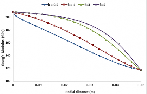
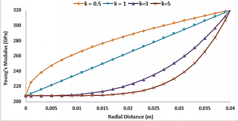
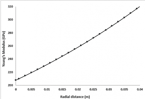
To validate the temperature dependent material gradation, an FG shaft consisting of SS-ZrO2 has been considered based on material data available in literature [15]. The radius (Ro) of the shaft is taken as 50mm, and the outer ceramic layer is kept at a temperature of 900K while the inner metal core is at room temperature. The variation of material properties such as Young’s Modulus, Poissons’s ratio and temperature distribution profile has been verified with works of Gayen et al. [19]. The plot of Young’s Modulus for different power-law coefficients obtained using the code is shown in Figure 5 Following this, the code has been used to generate a material distribution profile for a shaft with radius (Ro) 40 mm composed of SS-Al2O3, where both the outer ceramic surface and the inner core metal have been kept at room temperature. Figure 6. shows that the radial variations of the material properties obtained are in good agreement with the plots obtained from the works from the literature [18].
Figure 5. Young’s Modulus variation for different k values when Tm=300K and Tc= 900K for SS-ZrO2 FG shaft
Figure 6. Young’s Modulus variation for different k values when for Al2O3 FG shaft at room temperature
Figure 7. Young’s Modulus variation using exponential law for SS-Al2O3 FG shaft at room temperature
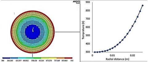
Figure 8. Temperature distribution profile using NLTD in SS-Al2O3 FG shaft ANSYS model
Further, the verification of material gradation generated using code has been carried out for exponential law. Due to the absence of significant literature results on shafts modelled using exponential law, graphical plots of the equations discussed in section 2.2 have been obtained. The exponential graded FG shaft is considered to be composed of SS-Al2O3 and having the same geometry as discussed in the previous section. The code calculates the temperature-dependent thermal conductivities, then obtains the radial variation of temperature following ETD. Following this, the temperature and position-dependent material properties are obtained. Poisson’s ratio is kept constant for the shaft by assuming the average value of the metal and ceramic Poisson’s ratio. Radial variation in Young’s modulus values is shown in Figure 7.
Figure 8 represents the radial variation of temperature achieved using NLTD for an FG shaft modelling using ANSYS. The power law coefficient is taken as 0.3 and the metal-core temperature (Tm) is 300K while the outer ceramic temperature (Tc) is 900K. The graphs obtained are the desired representation of the equation of exponential nature. The plots confirm that the code can be applied for exponential temperature distribution; thus, this can be extended further for studies on shafts with a circular cross-section.
5.2 Natural frequencies of simply supported FG shaft
To establish a confirmation between works on functional graded shaft available in the literature with the three-dimensional solid modelling carried out in present work natural frequencies of simply supported FG shaft, modelled using ANSYS have been compared with works of Gayen et al. [19].
The first two natural frequencies are presented for an FG shaft composed of SS and Al2O3, with a diameter (D) as 80mm and corresponding length (L) of 1 m. The power-law coefficient has been taken as 0.5. The shaft is kept at room temperature. For a layer thickness of 2mm, the natural frequencies obtained show significant confirmation with the literature, as shown in Table 3. The first and second natural frequencies have a variation of 0.027% and 1.4%, respectively with the literature results. Following this confirmation, the modelling technique has been for extended works on rotating FG shaft systems.
Table 3. Natural frequency (Hz) validation for simply supported FG shaft
|
Modes |
Present |
Gayen et al. [19] |
Difference (%) |
|
Simply supported FG (SS-Al2O3) shaft, k=0.5 |
|||
|
First |
255.99 |
255.92 |
+0.027 |
|
Second |
1003.5 |
1017.71 |
-1.4 |
5.3 Whirl frequencies of uniform steel rotor-bearing system
Analysis has been carried out for validation of the double-disc rotor model, as shown in Figure 4. The rotor system geometry, as discussed in section 3.1, is used in present work. The shaft system has been presented to be made of steel for validation purposes. The shaft ends are supported on identical isotropic bearings. The modelling of bearings and their properties are discussed in section 3.1 and 3.2. Whirl frequencies are recorded at stationary conditions and for a rotation speed of 4000 rpm. In Table 4 and compared with notable works on literature by Friswell et al. [25]. Results show significant agreement with literature. Frequencies occur in pairs at 0 revs/min; however, each pair separates when the shafts rotating speed is increased, due to the gyroscopic effects of shaft and discs. Further the shaft has been modelled using different FG materials following power and exponential law
Table 4. Whirl frequencies (Hz) at 4000 rpm for steel rotor disc system
|
Modes |
Present |
Friswell et al. [25] |
Difference (%) |
|
Steel double disc shaft system |
|||
|
1 BW |
13.2 |
13.10 |
+0.76 |
|
1 FW |
13.88 |
13.82 |
+0.43 |
|
2 BW |
38.4 |
38.14 |
+0.68 |
|
2 FW |
45.8 |
45.72 |
+0.17 |
A double disc FG rotor bearing system, shown in Figure 4 is composed of SS-Al2O3, is considered to investigate the natural frequencies and whirl effects. Modelling has been done involving both power and exponential law. The effect of material gradation on whirl frequencies has been studied. Campbell diagrams have been plotted to capture the backward and forward whirl frequencies. Attempts have been made to identify and present the trends in the variation of frequencies.
6.1 Effect of material gradation on natural frequencies at a constant temperature
Subsections 6.1.1 and 6.1.2 discuss effect of power law coefficients on natural frequency of FG shafts modelled using power law and exponential law respectively.
6.1.1 FG shaft system graded using power law without thermal gradient
The FG rotor bearing system shown in Figure 4 is considered. The radial variation of material properties has been achieved using power law gradation. The shaft is assumed to be at a constant temperature of 300K. Six power-law coefficients ranging from 0.3 to 10 are selected to investigate the effect on frequencies with a change in coefficients. Each coefficient generates a unique set of radially varying material properties. The first six whirl natural frequencies at 4000 rpm rotating speeds of the shaft has been presented in Table 5.
Table 5. Whirl frequencies (Hz) of SSAl2O3 FG shaft at 4000 rpm
|
Modes |
FGM comprising (Steel and Al2O3) |
||||||||
|
Power law |
Exp. law |
||||||||
|
|
k |
|
|||||||
|
|
0.3 |
0.5 |
1 |
3 |
5 |
10 |
|
||
|
1Bw |
16.46 |
16.3 |
16.09 |
15.54 |
15.2 |
14.8 |
16.23 |
||
|
1FW |
16.71 |
16.5 |
16.35 |
15.82 |
15.5 |
15.2 |
16.23 |
||
|
2Bw |
47.24 |
46.8 |
46.07 |
44.49 |
43.7 |
42.9 |
50.39 |
||
|
2FW |
55.88 |
55.3 |
54.35 |
52.35 |
51.4 |
50.4 |
50.39 |
||
|
3Bw |
135.5 |
134 |
131.8 |
125.5 |
121. |
117. |
130.7 |
||
|
3FW |
186.9 |
182. |
174.2 |
159.3 |
153 |
147 |
176.4 |
||
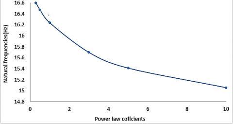
Figure 9. Natural frequency variation for SS-Al2O3 FG rotor system modelled using power law at room temperature
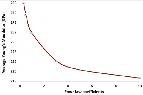
The natural frequencies of the shaft systems at stationary condition show a decreasing trend with an increase in the value of power-law coefficients. The decrease in frequencies occurs in a non-linear fashion. The variation of natural frequencies with power law index is shown in Figure 9. The curve clearly illustrates that the slope of the curve decreases gradually. This shows that the decrease in natural frequencies occur at a slower rate for a higher power-law coefficient. The reason for this behavior can be attributed to the variation of average Young’s modulus for the FG shaft with power law coefficients (Figure 10). The plot exhibits that at lower values of power law index there is a steep drop in average stiffness of the FG shaft, however as the power law coefficients increase the drop becomes gradual.
Figure 10. Variation in average Young’s modulus for SS-Al2O3 FG rotor system with power law index at room temperature
Figure 11. First BW/FW frequencies at 4000 rpm for SS-Al2O3 FG shaft without thermal
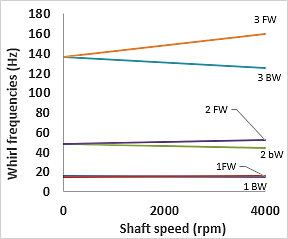
Figure 12. Campbell diagram for FG rotor system modelled using power law (k=0.3)
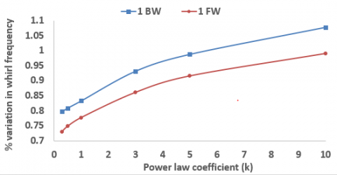
Another trend in whirl frequencies is observed at a shaft rotation speed of 4000rpm. The percentage of the separation in frequencies at 4000 rpm with respect to stationary shaft frequencies has been investigated. The percentage variation in whirl frequencies is calculated using Eq. (13). Where $\omega_{4000}$ and $\omega_{0}$ represent forward/backward whirl frequency at 4000 rpm and 0 rpm respectively.
$Percentage variation in whirl frequency=\frac{\omega_{4000}-\omega_{0}}{\omega_{0}} x 100 \%$ (13)
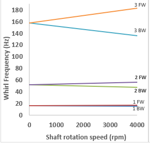
The trends of the percentage differences have been represented graphically shown in Figure 11 The separation of both first backward (1BW) and first forward whirl (1FW) frequencies have been examined. Both are found to increase with the rise in power-law coefficients. It can also be noted that the percentage difference of 1st FW frequency is less than 1st BW frequency at any k value. This behavior is due to the variation pattern of Young’s Modulus for the shaft system shown in Figure 10. Figure 12 shows the Campbell diagram for the SS-Al2O3 FG rotor system modelled using power law with power law coefficient as 0.3.
6.1.2 FG shaft system graded using exponential law without thermal gradient
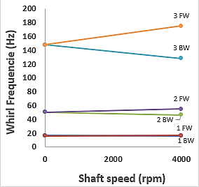
Results are generated similar to previous system, however the exponential gradation law is used to model the shaft system. The material properties such as Young’s modulus are varied using the exponential gradation but Poison’s ratio is taken as a constant. The average value of Poisson’s ratio of the metal and ceramic has been applied to the shafts. The whirl frequencies have been computed at the stationery condition and at a speed of 4000rpm. The first three forward and backward whirl frequencies have been shown in Table 5.
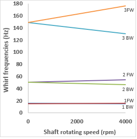
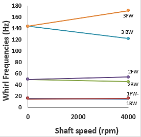
The results show that the natural frequencies obtained for SS-Al2O3 shaft frequency at power-law coefficient one corresponds to the frequencies obtained using exponential gradation. This nature can be expected as the material property distribution curve for exponential law Figure 7 are similar to the corresponding power law coefficient curve of material gradation, as shown in Figure 6. Due to gyroscopic effects of the shaft and the discs, separation of natural frequencies occurs at higher shaft speeds. Figure 13 represents the Campbell diagram obtained for the exponentially graded shaft system
Figure 13. Campbell diagram for FG rotor system modelled using exponential law
6.2 Effect of thermal gradient on whirl frequencies
To effects of thermal gradient on whirl frequencies of FG rotor systems are presented in this section. The SS-Al2O3 FG shaft as shown in Figure 4 is used for the analysis. Results have been presented for different thermal gradients and the reasons for the variations obtained have been investigated. The inner core metal temperature (Tm) and the outer ceramic temperature (Tc) of the shaft are varied to apply the effect of thermal gradation. The ceramic temperature is kept higher to replicate the general application conditions of FG material applications. The effects of booth NLTD and ETD have been discussed.
6.2.1 Shaft modelled using power law and NLTD
The whirl frequencies of the shaft system subjected to thermal gradients has been studied in this section. The shaft has been subjected to four different temperature gradients with different metal core (Tm) and outer ceramic temperatures (Tc). Table 6. shows the effect of temperature gradation (∆T) on first natural frequencies. The table also presents the effect of increasing metal core temperature (Tm) for the same temperature gradients on natural frequencies.
Table 6. Natural frequency comparison for different rotor system subjected to thermal gradients
|
Shaft type |
Tm=300K, Tc=300K, ∆T=0 |
Tm=600K, Tc=1200K∆T=600K |
Decrease (%) |
|
|
Power law graded FG shaft (k=0.3) |
16.59 |
16.25 |
+0.76 |
|
|
Exponentially graded FG shaft |
16.23 |
15.4 |
+0.43 |
|
|
Homogeneous Steel shaft |
13.10 |
11.12 |
+0.68 |
|
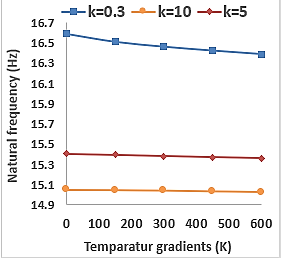
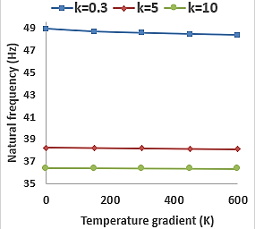
The trends obtained in the variation of these frequencies have been represented graphically in figures. In Figure 14, a reduction in natural frequencies occurs with an increase in temperature gradients for all metal core temperatures is observed. However, it is worth noting that this reduction is more prominent at lower k values. At higher k values, the reduction in natural frequencies is very less for an increase in a temperature gradient. To verify that the trend obtained is due to the FG shaft and does not depend on the effects due to the two discs, an FG shaft composed of SS-Al2O3 with same dimensions and boundary conditions but without the two discs has been modelled analysed. The inner metal core temperature (Tm) is kept at 300K. The trends in the variation of natural frequency for shafts made using different power law coefficients subjected to the same temperature gradients (∆T) have been represented graphically in Figure 15. Significant similarities in the trend can be observed between Figure 14 and Figure 15, validating that the characteristics of natural frequency variation is applicable to the FG shaft systems.
Figure 14. Natural frequency variation for FG shaft with disc
Figure 15. Natural frequency variation for FG shaft without disc
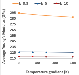
The reason for this behavior can be clearly seen in Figure 17, which represents the average elastic modulus of the FG shaft modelled using different k values with a change in thermal gradients. The Young’s modulus decreases with increase in temperature gradient for a shaft made by keeping power law coefficient as 0.3. However, the drop in average Young’s modulus of FG shaft having higher power-law coefficients (k=5 and k=10) is almost negligible. Thus, the lower change in elastic modulus corresponds to the small change in natural frequencies at higher power-law coefficients.
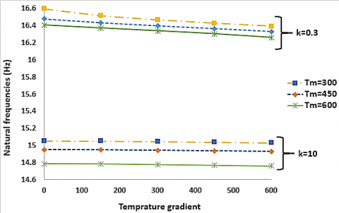
Figure 16. Variation of first natural frequencies with Tm for k = 0.3 and k = 10
Figure 17. Variation of average Young’s Modulus with temperature gradient for different power-law index (k)
Another significant observation is that at any power-law coefficient as the metal core temperature is increased, the natural frequencies keep decreasing. The reason for such trends is due to a reduction in Young’s modulus or stiffness of the shaft with increasing temperature. This variation in natural frequencies has been presented in Figure 16 for SS-Al2O3 shaft modelled using k=0.3. and k=10.
The effects of thermal gradient on whirl frequencies of the disc rotor systems have also been investigated. The shaft rotation speed is taken as 4000 rpm, and the separation of frequency pairs produces forward and backward whirl. The results show that the whirl frequencies also follow the general trend, i.e. their values decrease with the increase of temperature gradient. The splitting of both BW and FW frequency increase with the rise in temperature gradient for SS-Al2O3 shaft which is evident from the Campbell diagrams shown in Figure 18.
Figure 18. Campbell diagram- k=5, NLTD Tm=600K, Tc=900K
6.2.2 Shaft modelled using exponential law and ETD
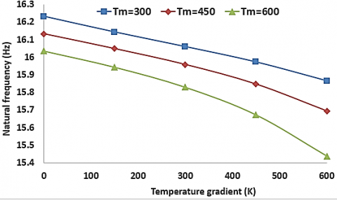
The effect of the thermal gradient on natural frequencies has been examined for shaft system modelled using exponential law. The temperature profile has been generated using the Exponential temperature distribution method. The trends obtained in the variation of these frequencies are shown in Figure 19. It can be noted that the natural frequencies decrease as expected, but the decrease is more significant when compared to shafts modelled using power law having same temperature gradients. Percentage decrease in the natural frequencies of SS-Al2O3 shaft modelled using power law for k value of 0.3 with metal-core temperature 300K is 1.22%. Whereas the percentage decrease is 2.25%. for exponentially graded shaft having the same geometry and with same metal-core temperature.
Further as shown in Figure 19, for a power law graded FG shaft, the rate of decrease in first natural frequencies decreases with a rise metal-core temperature (Tm). However, for an exponentially graded FG shaft, the rate of decrease in natural frequencies rises with the increase in metal core temperature (Tm).
Figure 19. Natural frequency variation for exponentially graded FG shaft under thermal gradient
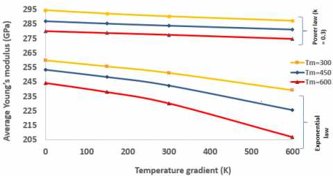
The reasons for the variations can be attributed to the variation of Young’s modulus of the shaft system with temperature. Figure 20 shows the variation of average Young’s modulus with increasing temperature gradients. The upper portion of the graph represents the FG (SS-Al2O3) shafts modelled using power law (k=0.3) and NLTD while the lower portion refers to shafts following exponential gradation and ETD. The plot clearly shows that average Young’s modulus decreases at decreasing rate with increasing temperature gradient when the power law is used to model but it falls at an increasing rate with an increase in temperature gradient for exponentially graded shafts. The difference in average elastic modulus becomes more significant with increase in temperature gradient for exponentially graded FG shafts.
Figure 20. Average Young’s modulus variation for exponentially graded FG shaft under thermal gradient
Figure 21. Campbell diagram (ETD, Tm=300K, Tc= 600K)
Figure 22. Campbell diagram (ETD, Tm=600K, Tc= 900K)
The first three FW and BW frequencies for the shaft system, rotating at a speed of 4000 rpm, subjected to different temperature gradients are analysed. The Campbell diagrams have been plotted for shaft systems subjected to thermal gradients shown in Figure 21 and Figure 22. The splitting of whirl frequencies increases with the increase in the temperature gradients and metallic core temperature. The reason for this behavior is due to the rate of variation of average Young’s modulus for the FG shaft at different temperature gradients. Table 6 depicts the first natural frequency of different rotor systems subjected to thermal gradients. The advantage of using FG shafts at higher temperature can be inferred from the results. FG shafts graded using power law and exponential law show small difference in frequencies at higher temperatures. However, for a homogenous stainless-steel shaft, the fall in natural frequencies is significant. The reason for this the abrupt decline in Young’s modulus of steel at higher temperatures (above 900K).
Three-dimensional finite element analysis has been carried out to investigate the vibration characteristics of ceramic based FG double-disc rotor systems. The FG shaft is composed of SS- Al2O3. Shafts are modelled following power law gradation with NLTD and exponential gradient with ETD. Shafts are modelled following power law gradation with NLTD and exponential gradient with ETD. Whirl frequencies are determined at different shaft speeds to understand the percentage change in backward and forward whirl frequencies.
Variations in natural frequencies has been studied for shafts subjected to different thermal gradations. Variations have been depicted and reasons for the variations have been discussed in detail. The following conclusions are made from discussed in detail. The following conclusions are mathe analysis.
Future works in this direction would include the effect of different bearing characteristics and to understand the effect cracks on the vibration characteristics of the FG materials.
[1] Dimentberg, F.M. (1961). Flexural Vibrations of Rotating Shafts. London: Butterworths.
[2] Ruhl, R., Booker, J.F. (1972). A finite element model for distributed parameter turbo rotor systems. Journal of Engineering for Industry, 94(1): 128-132. https://doi.org/10.1115/1.3428101
[3] Lund, J.W. (1974). Stability of damped critical speeds of a flexible rotor in fluid film bearings. Journal of Engineering for Industry, 96(2): 509-517. https://doi.org/10.1115/1.3438358
[4] Zorzi, E.S., Nelson, H.D. (1977). Finite element simulation of rotor-bearing systems with internal damping. Journal of Engineering for Power, 99(1): 71-76. https://doi.org/10.1115/1.3446254
[5] Nelson, H.D., Mcvaugh, J.M. (1976). The dynamics of rotor bearing systems using finite elements. Journal of Engineering for Industry, 98(2): 593-600. https://doi.org/10.1115/1.3438942
[6] Nelson, H.D. (1980). A finite rotating shaft element using Timoshenko beam theory. Journal of Mechanical Design, 102(4): 793–803. https://doi.org/10.1115/1.3254824
[7] Özgüven, H.N, Özkan, Z.L (1984). Whirl speeds and unbalance response of multibearing rotors using finite elements. Journal of Vibration, Acoustics, Stress, and Reliability in Design, 106(1): 72-79. https://doi.org/10.1115/1.3269158
[8] Bever, M.B., Duwez, P.E. (1972). Gradients in composite materials. Materials Science and Engineering, 10: 1-8. https://doi.org/10.1016/0025-5416(72)90059-6
[9] Shen, M., Bever, M.B. (1972). Gradients in polymeric materials. Journal of Materials Science, 7(7): 741–746. https://doi.org/10.1007/BF00549902
[10] Gayen, D, Tiwari, R., Chakraborty, D. (2019). Static and dynamic analyses of cracked on functionally graded structural components: A review. Composites Part B: Engineering, 173: 106982. https://doi.org/10.1016/j.compositesb.2019.106982
[11] Sankar, B.V. (2001). An elasticity solution for functionally graded beams. Composites Science and Technology, 61(5): 689-696. https://doi.org/10.1016/S0266-3538(01)00007-0
[12] Chakraborty, A., Gopalakrishnan, S., Reddy, J.N. (2003). A new beam finite element for the analysis of functionally graded materials. International Journal of Mechanical Sciences, 45(3): 519-539. https://doi.org/10.1016/S0020-7403(03)00058-4
[13] Shao, Z.S. (2005). Mechanical and thermal stresses of a functionally graded circular hollow cylinder with finite length. International Journal of Pressure Vessels and Piping, 82(3): 155-163. https://doi.org/10.1016/j.ijpvp.2004.09.007
[14] Xiang, H.J., Yang, J. (2008). Free and forced vibration of a laminated FGM Timoshenko beam of variable thickness under heat conduction. Composites Part B: Engineering, 39(2): 292-303. https://doi.org/10.1016/j.compositesb.2007.01.005
[15] Reddy, J.N., Chin, C.D. (1998). Thermoelastical analysis of functionally graded cylinders and plates. Journal of Thermal Stresses, 21(6): 593-626. https://doi.org/10.1080/01495739808956165
[16] Shahba, A., Attarnejad, R., Marvi, M.T., Hajilar, S. (2011). Free vibration and stability analysis of axially functionally graded tapered Timoshenko beams with classical and non-classical boundary conditions. Compos Part B: Engineering, 42(4): 801-808. https://doi.org/10.1016/j.compositesb.2011.01.017
[17] Gayen, D., Roy, T. (2014). Finite element based vibration analysis of functionally graded spinning shaft system. Journal of Mechanical Engineering Science, 228(18): 3306-3321. https://doi.org/10.1177/0954406214527923
[18] Gayen, D., Chakraborty, D. (2018). Free vibration analysis of functionally graded shaft system with a surface crack. Journal of Vibration Engineering & Technologies, 6: 483-494. https://doi.org/10.1007/s42417-018-0065-9
[19] Gayen, D., Chakraborty, D., Tiwari, R. (2016). Whirl frequencies and critical speeds of a rotor-bearing system with a cracked functionally graded shaft – Finite element analysis. European Journal of Mechanics - A/Solids, 61: 47-58. https://doi.org/10.1016/j.euromechsol.2016.09.003
[20] Arnab, B., Prabhakar, S. (2019). Natural frequency analysis of a functionally graded rotor system using the three-dimensional finite element method. Vibroengineering PROCEDIA, 29: 70-75. https://doi.org/10.21595/vp.2019.21099
[21] Aboudi, J., Pindera, M.J., Arnold, S.M. (1999). Higher-order theory for functionally graded material. Composites Part B: Engineering, 30(8): 777-832. https://doi.org/10.1016/S1359-8368(99)00053-0
[22] Touloukian, Y.S. (1967). Thermophysical Properties of High-Temperature Solid Materials. New York: McMillan.
[23] Kiani, Y., Eslami, M.R. (2010). Thermal buckling analysis of functionally graded material beams. International Journal of Mechanics and Materials in Design, 6(3): 229-238. https://doi.org/10.1007/s10999-010-9132-4
[24] Afsar, A.M., Go, J. (2010). Finite element analysis of thermoelastic field in a rotating FGM circular disk. Applied Mathematical Modelling, 34(11): 3309-3320. https://doi.org/10.1016/j.apm.2010.02.022
[25] Friswell, M.I., Penny, J.E.T., Garvey, S.D., Lees, A.W. (2010). Dynamics of Rotating Machines, Cambridge University Press, New York. https://doi.org/10.1017/CBO9780511780509
[26] ANSYS Theory Manual. https://ansyshelp.ansys.com/.