Younes Menni* | Ali J. Chamkha | Giulio Lorenzini | Boumédiène Benyoucef
OPEN ACCESS
A computational fluid dynamics based numerical simulation of thermal and thermo-hydraulic performance of a flat rectangular and V-shaped baffled channel of a solar air heater having various ribs, i.e., square, trapezoidal, triangular pointing upstream (called: triangular-upstream or I-type), triangular pointing downstream (called: triangular-downstream or II-type), and equilateral-triangular (called: III-type), on its absorber plate is carried out in the present work. Finite Volume Method (FVM), Semi Implicit Method for Pressure Linked Equations algorithm (SIMPLE), Quadratic Upstream Interpolation for Convective Kinetics numerical scheme (Quick), and Standard k-epsilon turbulence model (k-ε), by means of Commercial CFD software FLUENT are used in this recent simulation. The triangular-shape roughness geometry in II-type, at high values of Reynolds number, may be considered as the best operating regime when using the ribs for the lower surface of the upper hot wall to improve the heat transfer efficiency inside the channel.
Nusselt number, skin friction coefficient, thermal enhancement factor, ribs, obstacles, CFD
The topic is of paramount importance. Solar air channels are used in several sectors and in very diverse fields. The improvement of their performance has been and is still of major concern to theorists and practitioners. Tamna et al. [1] reports a study on heat transfer enhancement in a solar air heater channel fitted with multiple V-baffle vortex generators. Sriromreun et al. [2] conducted an experimental and numerical study to examine the heat transfer and flow friction characteristics in a channel of aspect ratio of 10 fitted with the in-phase and out-phase 45° Z-baffles in the turbulent regime from Re = 4400 to 20,400. Skullong et al. [3] presented an experimental study on turbulent flow and heat transfer characteristics in a solar air heater channel fitted with combined wavy-rib and groove turbulators. Saini and Saini [4] carried out an experimental study for enhancement of heat transfer coefficient of a solar air heater having roughened air duct provided with artificial roughness in the form of arc-shape parallel wire as roughness element. Tian and Zhao [5] reviewed the state of the art on solar thermal applications, with the focus on the two core subsystems: solar collectors and thermal energy storage subsystems. Alam and Kim [6] reported the comprehensive literature review on double pass solar air heaters (SAHs) with an aim to emphasize the various configurations, and heat transfer enhancement techniques used in double pass SAH. Kabeel et al. [7] presented a review of the literature dealing with improvement methods, design configurations and applications of different types of solar air heaters (SAHs). Oztop et al. [8] reviewed the previously conducted studies and applications in terms of design, performance assessment, heat transfer enhancement techniques, experimental and numerical works, thermal heat storage, effective- ness compassion and recent advances. Singh et al. [9] conducted experiments on rectangular duct having one broad wall roughened with discrete V-down rib and subjected to constant heat flux. Alam et al. [10] experimentally investigated the effect of geometrical parameters of the V-shaped perforated blocks on heat transfer and flow characteristics of rectangular duct. Kumar and Kim [11] reviewed the investigations carried out by various investigators to enhance the Nu and pressure drop by the use of ribs and baffles of different shapes, sizes, and orientations to produce artificial roughness. Ziyadanogullari et al. [12] experimentally investigated the effects on thermal efficiency of nanofluid and water as working fluids in flat-plate solar collector hot water solar energy systems. Sharafeldin and Grof [13] performed an experimental study to detect the effect of the WO3 nanoparticles on the performance of the evacuated tube solar collector. A comparison between three different volume fraction concentrations of the WO3 nanoparticles of 0.014 %, 0.028 %, and 0.042 % was held. Dehaj and Mohiabadi [14] investigated an evacuated heat pipe solar collector (HPSC) experimentally. The main aim was to study the efficiency of the HPSC. An experimental apparatus for testing solar heat pipe collectors was designed and built at Vali-e-Asr University.
This paper reports a computational fluid dynamics (CFD) based numerical simulation on the thermal and thermo-hydraulic performance of a solar air flat rectangular and V-upstream baffled channel fitted with variously-shaped ribs on its hot upper wall under turbulent condition.
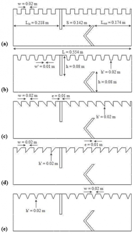
The thermal and thermo-hydraulic performance inside a solar air channel of rectangular section with variously-shaped ribs mounted on its top surface is studied and analyzed numerically. The physical model under consideration is shown in Figure 1. The top surface of the channel is put in a constant temperature condition, while the bottom one is thermally insulated. Two transverse obstacles, having different shapes, i.e. flat rectangular and V-shaped, are inserted into the channel and fixed to its upper and lower walls, in a staggered manner to force vortices to improve the mixing and consequently the heat transfer.
Figure 1. Configuration of various-shaped ribs arranged in a baffled channel: (a) square-shaped ribs, (b) trapezoidal-shaped ribs, (c) triangular-shaped ribs pointing upstream (or I-type triangular-shape roughness), (d) triangular-shaped ribs pointing downstream (or II-type triangular-shape roughness), and (e) equilateral-triangular shaped ribs (or III-type triangular-shape roughness)
The structural parameters, i.e., channel height (H) and length (L), inlet (Lint) and outlet (Lout) distances, baffle height (h), thickness (e), and separation distance (S), have been based on the numerical and experimental analysis of Demartini et al. [15].
Computational fluid dynamics based simulations are conducted for five hot top surface-attached rib shapes, namely square, trapezoidal, triangular pointing upstream (called: triangular-upstream or I-type), triangular pointing downstream (called: triangular-downstream or II-type), and equilateral-triangular (called: III-type). The dynamic thermo-energy behavior of air was presented for Reynolds numbers based on the hydraulic diameter of the channel ranging from 12,000 to 32,000. The specific geometry of this channel promotes turbulence and improves heat transfer. Several assumptions were considered:
- Flow and heat transfer are two-dimensional;
- Air flow is supposed to be turbulent;
- The physical properties of the fluid and solid are constant;
- The fluid is Newtonian and incompressible;
- Buoyancy induced effects, and radiation heat transfer mode are not considered.
- The fluid enters the channel with a constant temperature and uniform velocity profile.
The air as test fluid with constant properties at 300 K flows into the channel [16]. A uniform one-dimensional velocity profile (u = Uin, v = 0) is applied at the inlet of the channel [15,16]. Impermeable boundary and no-slip wall conditions are implemented over the channel walls as well as the obstacle and roughness surfaces. Note that the atmospheric pressure (Patm) is prescribed at the channel outlet [15].
For the thermal boundary conditions, the top wall of the channel is kept at constant temperature (Tw = 375 K) while the bottom wall is assumed to be adiabatic.
The steady state governing flow equations for the conservation of mass, momentum and energy used to study the fluid flow and heat transfer characteristics in the channel are presented in Ref [17].
The Finite Volume Method of Patankar [18], by means of Commercial CFD software FLUENT, is used in the present simulation. The standard k-epsilon model [19] is used to simulate the turbulence phenomenon. The SIMPLE (Semi-Implicit Pressure Linked Equation) algorithm of Patankar [18] is used for pressure velocity coupling. The QUICK (Quadratic Upstream Interpolation for Convective Kinematics) scheme in the form given by Leonard and Mokhtari [20] is selected to discretize the convective terms in the governing equations, while a Second-order upwind scheme [18] is used for the pressure terms. The numerical model was validated successfully (under similar flow and geometry conditions: air fluid, rectangular channel with staggered two baffle plates, Re = 8.73 × 10⁴, Uin = 7.8 m/s). See Ref. [21]).
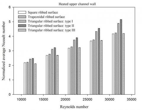
The calculations of the heat transfer rate are carried out over the hot upper wall of the channel, while the bottom surface is kept at ambient temperature. The results of the heat transfer are all expressed in terms of the normalized average Nusselt number (Nu/Nu0) along the length of the hot upper channel wall. The quantity Nu0 is the average Nusselt number for the turbulent forced-convection flow in a smooth air channel, for the same Reynolds number. The normalized mean Nusselt number (Nu/Nu0) is the parametric quantity used to determine the areas with the lowest heat transfer within the channel. Setting obstacles and ribs inside the channels is generally meant to improve the heat transfer rate as compared to the channels without obstacles and ribs. If the above mentioned number is smaller than 1, the heat transfer is poor. However, the heat transfer performance is good when that number is larger than 1. Simulation of the flow was carried out for the Reynolds number equal to 12,000, 17,000, 22,000, 27,000, and 32,000. The heat transfer rate is plotted as a function of the ribbed surface geometry (i.e., square, trapezoidal, and triangular ribbed surfaces), in Figure 2. When the Reynolds number rises from 12,000 to 32,000, the rate of heat transfer increases significantly for all ribbed surface cases, thus introducing large recirculation zones. In all instances, the flows inside the baffled channel roughened by variously shaped ribs on the hot upper surface gives more significant Nusselt number values than in a smooth rectangular channel, in the absence of fins, baffles, and ribs (Nu/Nu0 > 1) because high recirculation cells and a thin boundary layer are induced within the channel with obstacles and ribs, which results in higher temperature gradients.
Figure 2. Variation of normalized Nusselt number with Reynolds number for various ribs
The first obstacle, fin of flat rectangular shape, sends the flow towards the insulated bottom wall, but the second one (45° V-shaped baffle pointing upstream) guides it in the direction of the hot upper wall (ribbed surface), and this allows the fluid to pick up the entire thermal energy from the hot wall. The maximum value of the ratio Nu/Nu0 is found for triangular-configuration in II-type while the lowest value corresponds to square-configuration at the highest value of Reynolds number, Re = 32,000. This means that the recirculation flow created by the ribbed and baffled walls, with smaller recirculation lengths, is not sufficiently strong to provide a considerable mixing or turbulence intensity of the flow between the hot surface of the channel and the core; this case should be kept off. The results obtained are found to be consistent with those reported by several authors who confirm that some recirculation zones appear locally; this corresponds to a more significant heat transfer (see for example, Nasiruddin and Kamran Siddiqui [16]). Considering our study range, from Re=12,000 to Re=32,000, one can say that the average Nusselt number (Nu) gains for the hot top surface cases with square, trapezoidal, triangular (I-Type), triangular (II-type), and triangular (III-type) shaped ribs are within the intervals 218.981 - 416.828 %; 222.478 - 423.019 %; 243.424 - 489.126 %; 248.426 - 515.981 %; and 211.940 - 419.891 %, respectively, along the smooth air rectangular channel with no obstacles and ribs. The square, trapezoidal, I-type triangular, and III-type triangular shaped ribs show reductions of about 19.216 %, 18.016 %, 5.204 %, and 18.622 %, respectively, in heat transfer rate relative to that of the triangular-shaped rib in II-type, at the same value of Reynolds number, Re=32,000.
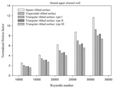
Figure 3. Variation of normalized friction factor with Reynolds number for various ribs
By and large, the increase in heat transfer is not enhanced by the rise of the coefficient of skin friction, as this would lead to a larger pressure decline. The evolution of the friction factor ratio (f/f0) at the hot upper channel surface with different types of ribs, for various values of the Reynolds number (Re), is shown in Figure 3. In the present situation, f0 is the friction factor in a smooth air channel, with the same Reynolds number. This same figure shows that the increase in the factors of friction loss is more significant than the one of the coefficients of heat transfer generated by the temperature field. This may suggest that the velocity and turbulence fields grow faster than the isotherms. The number of Reynolds has an impact on the normalized mean coefficient of skin friction; a correlation exists between the two variables. Indeed, increasing the Reynolds number results in a substantial growth in the fluid velocity; the losses due to skin friction are also very significant. For Reynolds numbers within the interval from 12,000 to 32,000, and square, trapezoidal, I-type triangular, II-triangular, and III-type triangular shaped ribs, the friction factor increases by about 2.550 - 11.663; 2.062 - 9.248; 1.838 - 8.015; 1.841 - 8.338; and 1.571 - 7.341 times, respectively, over the smooth rectangular cross section channel, in the absence of obstacles and ribs. The figure also shows that the geometry of the heated upper surface has a significant impact on the skin friction loss, for all the instances under consideration. The friction factor of triangular-shaped ribs was lower than that of square and trapezoidal-shaped ribs, which shows that the triangular-shaped rib is more advantageous than the other cases studied. Furthermore, the use of triangular-shaped ribs in III case gives lower friction loss than that in I and II cases around 9.168 % and 13.568 %, respectively, at the highest value of the Reynolds number, Re=32,000. However, using ribs in square geometry leads to a larger skin friction loss rate than that obtained in trapezoidal, I-type triangular, II-type triangular, and III-type triangular geometries. It is higher by about 20.712 %, 31.282 %, 28.513 %, and 37.054 % respectively, at the maximum Reynolds number, Re=32,000.
Figure 4. Variation of thermal enhancement factor with Reynolds number for various ribs
Figure 4 is plotted using the thermal performance factor (TEF) given by Eq. (7) in Ref. [21]. Different rib configurations (i.e., square, trapezoidal, and triangular-shaped) simulated in this investigation are assessed and compared. In the figure, the TEF value tends to increase with augmenting the Re number for all ribs types. It is found that the TEF values vary between 1.610 - 1.860; 1.765 - 2.033; 1.995 - 2.470; 2.036 - 2.567; and 1.827 2.175, for using the square, trapezoidal, I-type triangular, II-type triangular, and III-type triangular shaped ribs, respectively, depending on the Re values. Accordingly, the enhancement factors, of the baffled channel with ribs of various types, in simple (square-shaped) or modern (trapezoidal and triangular-shaped) configurations, turn out to be above the unity for all cases; they are between 1.610, in the case of a roughened channel provided with square-shape roughness geometry for the lowest value of the Reynolds number (12,000), and 2.567 in the case of a roughened channel fitted with II-type triangular-shape roughness geometry for the maximum value of the Reynolds number (32,000), suggesting better thermal performance as compared to the smooth air rectangular cross section channel, in the absence of obstacles and ribs. The use of the rib leads to extremely considerable increase in the thermal enhancement factor in comparison with the baffled channel [21], in the absence of ribs. The increases in TEF values for using square, trapezoidal, I-type triangular, II-type triangular, and III-type triangular shaped ribs, respectively, are about 101.464 %, 110.891 %, 134.697 %, 139.971 %, and 118.626 % over the baffled channel with no rib, at the same upper value of the Reynolds number, Re = 32,000. The TEF values for both the triangular pointing upstream (or I-type) and the equilateral-triangular (or III-type), at Re=32,000, are around 3.768 %, and 15.249 % lower than that for the triangular pointing downstream (or II-type). Therefore, the triangular-shape roughness geometry in case II (triangular-shaped rib pointing downstream), at the highest value of the Reynolds number, Re = 32,000, may be considered as the best operating regime when using the ribs for the lower surface of the hot wall to improve the heat transfer phenomenon inside this recent channel.
The most important conclusions that can be drawn from this study are as follows:
The heat transfer results obtained are found to be consistent with those reported by several authors who confirm that some recirculation zones appear locally; this corresponds to a more significant heat transfer (see for example, Nasiruddin and Kamran Siddiqui [16]).
Over the Re range investigated, 12,000 - 32,000, the average Nusselt number (Nu) gains for the hot top surface cases with square, trapezoidal, triangular (I-Type), triangular (II-type), and triangular (III-type) shaped ribs are within the intervals 218.981 - 416.828 %; 222.478 - 423.019 %; 243.424 - 489.126 %; 248.426 - 515.981 %; and 211.940 - 419.891 %, respectively, along the smooth air rectangular channel with no obstacles and ribs.
The square, trapezoidal, I-type triangular, and III-type triangular shaped ribs show reductions of about 19.216 %, 18.016 %, 5.204 %, and 18.622 %, respectively, in heat transfer rate relative to that of the triangular-shaped rib in II-type, at the same value of Reynolds number, Re = 32,000.
For all rib cases studied, the increase in the factors of friction loss is more significant than the one of the coefficients of heat transfer generated by the temperature field. This may suggest that the velocity and turbulence fields grow faster than the isotherms.
For Reynolds numbers within the interval from 12,000 to 32,000, and square, trapezoidal, I-type triangular, II-triangular, and III-type triangular shaped ribs, the friction factor increases by about 2.550 - 11.663; 2.062 - 9.248; 1.838 - 8.015; 1.841 - 8.338; and 1.571 - 7.341 times, respectively, over the smooth rectangular cross section channel, in the absence of obstacles and ribs.
The friction factor of triangular-shaped ribs was lower than that of square and trapezoidal-shaped ribs. Therefore, the triangular-shaped rib is more advantageous.
The use of triangular-shaped ribs in III case gives lower friction factor than that in I and II cases around 9.168 % and 13.568 %, respectively, at the highest value of the Reynolds number, Re = 32,000.
The increases in TEF values for using square, trapezoidal, I-type triangular, II-type triangular, and III-type triangular shaped ribs, respectively, are about 101.464 %, 110.891 %, 134.697 %, 139.971 %, and 118.626 % over the baffled channel with no rib, at the same upper value of the Reynolds number, Re = 32,000.
The triangular-shape roughness geometry in case II (triangular-shaped rib pointing downstream), at the highest value of the Reynolds number, Re = 32,000, may be considered as the best operating regime when using the ribs for the lower surface of the hot wall to improve the heat transfer phenomenon inside this recent channel.
[1] Tamna S, Skullong S, Thianpong C, Promvonge P. (2014). Heat transfer behaviors in a solar air heater channel with multiple V-baffle vortex generators. Solar Energy 110: 720-735. http://dx.doi.org/10.1016/j.solener.2014.10.020
[2] Sriromreun P, Thianpong C, Promvonge P. (2012). Experimental and numerical study on heat transfer enhancement in a channel with Z-shaped baffles. International Communications in Heat and Mass Transfer 39: 945-952. https://doi.org/10.1016/j.icheatmasstransfer.2012.05.016
[3] Skullong S, Kwankaomeng S, Thianpong C, Promvonge P. (2014). Thermal performance of turbulent flow in a solar air heater channel with rib-groove turbulators. International Communications in Heat and Mass Transfer 50: 34-43. http://dx.doi.org/10.1016/j.icheatmasstransfer.2013.11.001
[4] Saini SK, Saini RP. (2008). Development of correlations for Nusselt number and friction factor for solar air heater with roughened duct having arc-shaped wire as artificial roughness. Solar Energy 82: 1118-1130. https://doi.org/10.1016/j.solener.2008.05.010
[5] Tian Y, Zhao CY. (2013). A review of solar collectors and thermal energy storage in solar thermal applications. Applied Energy 104: 538-553. http://dx.doi.org/10.1016/j.apenergy.2012.11.051
[6] Alam T, Kim M-H. (2017). Performance improvement of double-pass solar air heater - A state of art of review. Renewable and Sustainable Energy Reviews 79: 779-793. http://dx.doi.org/10.1016/j.rser.2017.05.087
[7] Kabeel AE, Hamed MH, Omara ZM, Kandeal AW. (2016). Solar air heaters: design configurations, improvement methods and applications - A detailed review. Renewable and Sustainable Energy Reviews 70: 1189-1206. http://dx.doi.org/10.1016/j.rser.2016.12.021
[8] Oztop HF, Bayrak F, Hepbasli A. (2013). Energetic and exergetic aspects of solar air heating (solar collector) systems. Renewable and Sustainable Energy Reviews 21: 59-83. http://dx.doi.org/10.1016/j.rser.2012.12.019
[9] Singh S, Chander S, Saini JS. (2011). Heat transfer and friction factor correlations of solar air heater ducts artificially roughened with discrete V-down ribs. Energy 36: 5053-5064. http://dx.doi.org/10.1016/j.energy.2011.05.052
[10] Alam T, Saini RP, Saini JS. (2014). Experimental investigation on heat transfer enhancement due to V-shaped perforated blocks in a rectangular duct of solar air heater. Energy Conversion and Management 81: 374-383. http://dx.doi.org/10.1016/j.enconman.2014.02.044
[11] Kumar A, Kim MH. (2015). Convective heat transfer enhancement in solar air channels. Applied Thermal Engineering 89: 239-261. http://dx.doi.org/10.1016/j.applthermaleng.2015.06.015
[12] Ziyadanogullari NB, Yucel HL, Yildiz C. (2018). Thermal performance enhancement of flat plate solar collectors by means of three different nanofluids. Thermal Science and Engineering Progress. https://doi.org/10.1016/j.tsep.2018.07.005
[13] Sharafeldin MA, Grof G. (2019). Efficiency of evacuated tube solar collector using WO3/Water nanofluid. Renewable Energy 134: 453-460. https://doi.org/10.1016/j.renene.2018.11.010
[14] Dehaj MS, Mohiabadi MZ. (2019). Experimental investigation of heat pipe solar collector using MgO nanofluids. Solar Energy Materials and Solar Cells 191: 91-99. https://doi.org/10.1016/j.solmat.2018.10.025
[15] Demartini LC, Vielmo HA, Möller SV. (2004). Numeric and experimental analysis of the turbulent flow through a channel with baffle plates. Journal of the Brazilian Society of Mechanical Sciences and Engineering 26(2): 153-159. https://doi.org/10.1590/S1678-58782004000200006
[16] Nasiruddin, Kamran Siddiqui MK. (2007). Heat transfer augmentation in a heat exchanger tube using a baffle. International Journal of Heat and Fluid Flow 28(2): 318-328. https://doi.org/10.1016/j.ijheatfluidflow.2006.03.020
[17] Sahel D, Ameur H, Benzeguir R, Kamla Y. Enhancement of heat transfer in a rectangular channel with perforated baffles. Applied Thermal Engineering, http://dx.doi.org/10.1016/j.applthermaleng.2016.02.136
[18] Patankar SV. (1980). Numerical heat transfer and fluid flow. McGraw-Hill, New York, NY.
[19] Launder BE, Spalding DB. (1974). The numerical computation of turbulent flow. Computer Methods in Applied Mechanics and Engineering 3(2): 269-289. http://doi.org/10.1016/0045-7825(74)90029-2
[20] Leonard BP, Mokhtari S. (1990). Ultra-sharp nonoscillatory convection schemes for high-speed steady multidimensional flow. NASA TM1-2568, NASA Lewis Research Center.
[21] Menni Y, Azzi A, Chamkha AJ, Harmand S. (2018). Effect of wall-mounted V-baffle position in a turbulent flow through a channel: Analysis of best configuration for optimal heat transfer. International Journal of Numerical Methods for Heat & Fluid Flow. https://doi.org/10.1108/HFF-06-2018-0270