Srikanth Ravipati* | Venkatesan Mani | SrinivasaRao Yarlagadda
© 2021 IIETA. This article is published by IIETA and is licensed under the CC BY 4.0 license (http://creativecommons.org/licenses/by/4.0/).
OPEN ACCESS
The present society suffers with the problem of the greenhouse effect due to the emission of huge amount of carbon dioxide. And almost 70% of emission of carbon dioxide will be due to the usage of automotive vehicles. It is required to reduce the utilization of automotive vehicles to protect the life of earth for the coming years. This manuscript presents the design of electric vehicle with the utilization of renewable energy source like solar energy with the combination of fuel cell energy. It involves the design of maximum power point tracking system with intelligent fuzzy controller to track the maximum power for various weather conditions. The proposed electric vehicle drives the brush less DC motor whose speed has been monitored with the sensor less speed control technique. The speed control technique has been realized with two types of controller’s namely proportional intelligent controller and radial basis function neural network. Also the speed control technique has been analysed with the performance comparison of the two controllers in terms of speed, torque generated and also errors of speed and current to improve the performance of speed by 5% with the help of MATLAB/Simulink.
Electric Vehicle, Proportional Integral Controller, Radial Basis Function Neural Network, Sensor Less BLDC motor.
Different environmental issues have led to the necessity of transformation from internal combustion-based vehicles to electric vehicles as it is known that conventional vehicle are the major cause for reducing the life of earth due to air pollution. Also the increase in price of fossil fuels is also one of the factors for opting the renewable energy sources. The solar energy (M. H. Rahman et al., 2019) is ahead among the numerous types of renewable sources in the aspect of reduced noise pollution, production of clean energy. Also, in addition to renewable energy source, fuel cell (W. Obaid et al., 2019) is also most advantageous source of generating electricity with the production of water as a byproduct. But the main problem of renewable energy source (O. Khurshid et al., 2019) is unable to track the maximum power for variable atmospheric and load conditions. Maximum power point tracking (R. Patil et al., 2017) is a technique of adjusting duty cycle of the converter such that maximum power can be tracked from the energy sources and also load voltage can be attained. There have been numerous tracking algorithms like incremental conductance, perturb-observe method, fractional open circuit voltage and fractional short circuit current which are very cost effective to implement and also simple in structure. The incremental conductance (S. K. Saha et al., 2018) is dependent up on the fact that slope of PV system power curve will be zero at MPP, positive on the left of MPP and negative on the right of MPP.
It tracks the maximum power more accurately in various climatic conditions and possesses the property of fewer oscillations around the maximum power point. But it suffers from the disadvantages of complexity in implementation and requirement of two sensors for implementation. Fractional open circuit voltage can be used for tracking the maximum power with open circuiting the load side and obtaining the maximum voltage with the measurement of open circuit voltage with continuous samples collection. It is easy to implement, but true peak point can never be obtained (R.Kumar et al., 2018). Perturb and observe method is based on the fact that if PV system operates to the left of peak point, output power will be increased with the increase in the voltage and if PV system operates to the right of peak point, output power will be decreased with the increase in the voltage. It is also easy to implement with good degree of tracking also improves static,dynamic performance of system.
The intelligent fuzzy controller has been chosen with MPPT controllers (S. Samal et al., 2018) as it possess several advantages like cost effective to implement, covering wide range of operating conditions, robust operation, increased reliability and higher precision with huge number of membership functions. The controlled output from the MPPT based distributed renewable system will be directed to brush less DC motor through inverter for driving the vehicle. The conventional DC motors can be used for driving the vehicle which is highly efficient, but the main drawback of the motors is requirement of commutator and brushes whose maintenance is very high. To avoid the problems with the commutator and brushes like sparking, brush less DC motor (K. Sreeram et al., 2018) has been chosen which will be driven by DC voltage with the current commutation controlled by switches. The current in phases of motor is rectangular in shape and synchronized with the back EMF, generating constant torque at constant speed. This motor will be controlled with inverter requiring sensor for sensing rotor position (K. M. Reshma et al., 2018) for starting and also for providing certain commutation sequence. The controlling of the inverter will be done in two ways namely sensor mode and sensor less mode. Sensor less control realizes the zero- crossing detection to determine position of the rotor. In this control, only two windings (K. Kroics et al., 2017) are excited with the third winding floated. To determine the zero- crossing time of EMF, voltage of the floating winding with respect to neutral point has to be determined. From the motor, using zero crossing detection (M. Štulrajter et al., 2017) the sensed position will be decoded and then sent to hall signal controller. This sensor less control involves certain advantages like elimination of sensors reducing the cost, reduced ripples in the torque, and increase in the capability. Also, to improve the performance of motor, the sensor less speed controller has been realized with conventional PI controller and radial basis function neural network. Radial basis function network is an artificial neural network (S. Chen et al., 2017) utilizing radial basis functions as activation functions. These neural networks possess several applications like pattern classification, prediction, function approximation and controlling. These neural networks differ from the conventional neural networks (T. Ho et al., 2017) in terms of universal approximation and faster training speed. It is a type of feed forward neural network comprising of an input layer, hidden layer and output layer with input layer encompasses of inputs, hidden layer with RBF activation function.
It approximates input-output mapping (D. Sorn et al., 2018) with linear combinations of radially symmetrical functions. These networks are analogous to the category of multi layer perceptron with larger input dimensions. Also these networks possess certain properties like simple in structure, easier to train and tolerance to input disturbance. So a radial basis function neural network has been chosen with three layers for controlling the speed of the motor with internal current controller.
The manuscript is organized as follows; Section I presents introduction to the proposed MPPT based hybrid electric vehicle with sensor less control of BLDC motor, Section II deals with the block drawing enlightment of proposed P&O-Fuzzy based MPPT and PI/RBFN based sensor less control of BLDC motor, Section III deals with the P&O-Fuzzy based MPPT tracking, Section IV deals with the PI/RBFN based sensor less control of BLDC motor, Section V deals with the simulation of the proposed vehicle and results. Section VI deals with the conclusions drawn from the proposed work.
The block diagram for the proposed sensor less speed control based electric vehicle is given in Figure 1. It comprises of solar panel, fuel cell, high gain interleaved boost converter,p&o- fuzzy controller based maximum power point tracking system, sensor less speed control strategy with PI controller and artificial neural network, three phase inverter and Brushless DC Motor. The integrated output from the solar with fuel cell system is directed to the high gain interleaved boost converter with the falling of irradiance on to solar panel and in flow of hydrogen into fuel cell. The high gain interleaved boost converter converts low voltage from the integrated system into high rated voltage with lower duty cycle attaining gate pulse from the MPPT controller.
Figure 1. Block diagram of proposed sensor less speed control based hybrid vehicle
2.1 PV panel and fuel cell explanation
When the sun rays fall on the solar cell, electrons flow occurs within the solar cell and the equivalent model of the solar cell is shown in Figure 2 consists of current source, diode and series resistance and parallel resistance and the open circuit voltage, short circuit current can be collected at the output terminal of the solar cell.
Figure 2. Equivalent circuit of solar cell
The equation for the current coming out from the solar cell can be given as
$I=I_{p h}-I_{D}-I_{s h}$ (1)
Where the current flowing through the diode can be given as
$I_{D}=I_{0}\left[e^{q\left(\frac{V+I R_{S}}{A K T}\right)}-1\right]$ (2)
The current flowing through the shunt resistance can be given as
$I_{s h}=\frac{V+I R_{S}}{R_{S h}}$ (3)
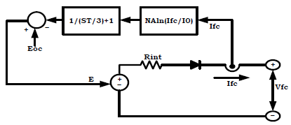
A fuel cell is a device which has the capability of producing electrical energy (W. Obaid et al., 2019) when hydrogen fuel is passed through one end of the fuel cell and when number of fuel cells is connected in series, parallel connection; it leads to fuel cell stack. The equivalent circuit of fuel cell is shown in Figure 3 consisting of voltage source diode and resistance.
The following are the equations (W. Obaid et al., 2019) explaining the operation of fuel cell The cell voltage of the fuel cell can be given as
$V_{f}=E-V_{a}-V_{b}-V_{c}$ (4)
The open circuit thermodynamic voltage can be given as
$\begin{aligned} E=1.229-0.00085(&T-298.15)+0.00004308 T\left(\ln \left(P_{H 2}\right)\right.\left.+0.5 \ln \left(P_{O 2}\right)\right) \end{aligned}$ (5)
The activation voltage which is a combination of anode and cathode voltage can be given as
$V_{a}=-\left[A_{1}+A_{2} T+A_{3} T \ln \left(C O_{2}\right)+A_{4} T \ln \left(I_{f c}\right)\right]$ (6)
The ohmic voltage can be given as
$V_{b}=\left(I_{f c} R_{a}+I_{f c} R_{b}\right)$ (7)
The concentration voltage can be given as
$V_{c}=-\frac{R T}{n F} \ln \left(1-\frac{J}{J_{m}}\right)$ (8)
Figure 3. Equivalent Circuit of Fuel Cell
The expression for the open circuit voltage can be given as
$E_{o c}=E_{n} K_{c}$ (9)
The current that can be collected through the fuel cell can be given as
$I_{0}=\frac{Z F K\left(P H_{2}+P O_{2}\right)}{R_{i n} h} e^{-\Delta G / R_{i n} T}$ (10)
Where $T$ is temperature, $R_{\text {in }}$ is internal resistance.
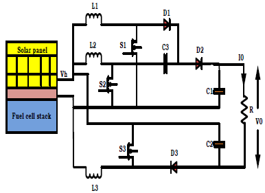
2.2 High gain interleaved boost converter
The high gain interleaved boost converter consists of three switches, three diodes for freewheeling operation, three filter inductors for three phases and three filter capacitors for three phases. The converter is assumed to be operated in continuous conduction mode with (K. Jyotheeswara Reddy et al., 2018) switching operation using 1800 phase shift. The expression for the capacitor at input side can be given as
$C_{3}=\frac{V_{0}}{R \Delta V f_{S}}$ (11)
The expression for the capacitors at output side can be given as
$C_{1}=C_{2}=\frac{D V_{0}}{R \Delta V f_{S}}$ (12)
The expression for the filter inductances can be given as
$L_{1}=L_{2}=L_{3}=\frac{D V_{h}}{\Delta I f_{s}}$ (13)
The expression for duty ratio can be specified as
$D=\frac{V_{0}-2 V_{h}}{V_{0}+V_{h}}$ (14)
Figure 4. Circuit diagram of high gain interleaved boost converter
2.3 BLDC motor
Brushless DC motor possesses simple structure with low cost when compared to AC motors there by utilizing in speed control techniques. They have advantages of superior speed torque characteristics with higher efficiency, increased dynamic performance when compared to brushed motors delivering greater torque.
2.3.1 Equivalent circuit of BLDC motor
The BLDC motor can be modeled as a 3 phase 4 pole machine with stator fed by three phase inverter. The expression for the voltages across the windings of the motor can be given as
$\left[\begin{array}{c}V_{a} \\ V_{b} \\ V_{c}\end{array}\right]=\left[\begin{array}{ccc}R_{s} & 0 & 0 \\ 0 & R_{s} & 0 \\ 0 & 0 & R_{s}\end{array}\right]\left[\begin{array}{l}i_{a} \\ i_{b} \\ i_{c}\end{array}\right]+\frac{d}{d t}\left[\begin{array}{ccc}L_{s} & 0 & 0 \\ 0 & L_{s} & 0 \\ 0 & 0 & L_{s}\end{array}\right]\left[\begin{array}{l}i_{a} \\ i_{b} \\ i_{c}\end{array}\right]+\left[\begin{array}{l}e_{a} \\ e_{b} \\ e_{c}\end{array}\right]$ (15)
Figure 5. Equivalent circuit of BLDC motor
The expression for the electromotive force can be given as
$\sin \theta_{e}$
$E=\frac{k}{p}\left[\begin{array}{c}\sin \left(\theta_{e}-\frac{2 \pi}{3}\right) \\ \sin \left(\theta_{e}-\frac{4 \pi}{3}\right)\end{array}\right] \frac{d \theta_{e}}{d t}$ (16)
The expression for the rotor angle can be given as
$\theta_{e}=\frac{p}{2 \theta_{m}}$ (17)
The expression for electromagnetic torque can be given as
$T_{e}=\frac{\left(e_{a} i_{a}+e_{b} i_{b}+e_{c} i_{c}\right)}{w}$ (18)
The expression for mechanical torque that can be transferred to the shaft of the motor can be given as
$T_{e}-T_{l}=J \frac{d w}{d t}+B w$ (19)
2.4 Sensor less control of BLDC motor
BLDC motors are driven by the DC voltage obtained from the inverter with current commutation being controlled by power semiconductor devices. In general the instants of commutation will be determined by sensor at the rotor position but the proposed control technique eliminates the use of sensors. So to obtain the speed and to control the switching states, sensor less control (K. M. Reshma et al., 2018) is proposed which works with the help of zero crossing detection. The proposed Sensor less control uses two loop with outer speed loop and inner current loop. The outer speed loop utilizes zero crossing detection for attaining the speed of the motor.
Then the actual speed obtained from the ZCD will be compared (M. Murali et al., 2018) with the reference speed and then fed to the controller finding the reference current. The actual current of the motor will be compared with the reference current (S. M. Allam et al., 2019) in the inner current loop generating processed error with the controller. Then the processed error will be used for generating gate signals for the inverter.
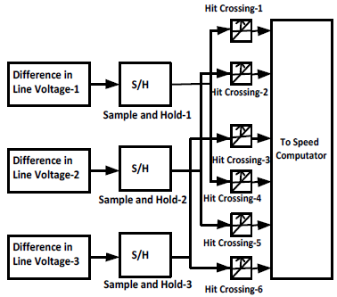
2.4.1 Zero crossing detection
Zero crossing detection determines the position of the rotor eliminating the use of rotor with two windings excited and third winding in floated condition. To attain the zero crossing time of back Emf, terminal voltage to neutral point of the floating winding will be determined. The output line voltages from the inverter will be fed to the line to line voltage difference block which determines the difference of line voltages of the three phases and then the differences being sent to sample and hold circuit. The sample and hold circuit samples the line voltage differences of the three phase and the samples will be sent to zero crossing detection block. The ZCD block determines the zero crossings of the samples during negative and positive zero crossings.
Figure 6. Internal circuit of zero crossing detection
The phase to neutral voltages can be expressed as
$V_{a n}=i_{a} R_{s}+L_{s} \frac{d i_{a}}{d t}+e_{a n}$ (20)
$V_{b n}=i_{b} R_{s}+L_{s} \frac{d i_{b}}{d t}+e_{b n}$ (21)
$V_{c n}=i_{c} R_{s}+L_{s} \frac{d i_{c}}{d t}+e_{c n}$ (22)
2.4.2 Phase current of BLDC motor
The expression for the line voltage between phase ‘a’ and phase ‘b’ can be given as
$V_{a b}=V_{a n}-V_{b n}$ (23)
$V_{a b}=R_{s}\left(i_{a}-i_{b}\right)+L_{s} \frac{d\left(i_{a}-i_{b}\right)}{d t}+e_{a n}-e_{b n}$ (24)
The expression for the line voltage between phase ‘b’ and phase ‘c’ can be given as
$V_{b c}=V_{b n}-V_{c n}$ (25)
$V_{b c}=R_{s}\left(i_{b}-i_{c}\right)+L_{s} \frac{d\left(i_{b}-i_{c}\right)}{d t}+e_{b n}-e_{c n}$ (26)
The expression for the line voltage between phase ‘c’ and phase ‘a’ can be given as
$V_{c a}=V_{c n}-V_{a n}$ (27)
$V_{c a}=R_{s}\left(i_{c}-i_{a}\right)+L_{s} \frac{d\left(i_{c}-i_{a}\right)}{d t}+e_{c n}-e_{a n}$ (28)
The expression for difference in the line voltage can be given as
$V_{a b b c}=V_{a b}-V_{b c}$ (29)
$V_{a b b c}=\left(i_{a}-2 i_{b}+i_{c}\right) R_{s}+\frac{L_{s} d\left(i_{a}-2 i_{b}+i_{c}\right)}{d t}+e_{a n}-2 e_{b n}+e_{c n}$ (30)
Considering the condition of floated terminal such that phase B is in open so that
$i_{a}=-i_{c}$ (31)
$i_{b}=0$ (32)
Then the difference in line voltage can be rewritten as
$V_{a b b c}=e_{a n}-2 e_{b n}+e_{c n}$ (33)
$V_{a b b c}=-2 e_{b n}$ (34)
From the equations (20-34), it can be shown that phase B changes from one polarity to other polarity enabling zero crossing. Similarly all the other phases change their polarity enabling zero crossing.
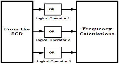
2.4.3 Speed computation
From the zero crossing detectors, the decoding will be done with logical operations there by attaining three decoding signals.
Figure 7. Internal circuit of speed computation
From the decoding signals using time period, frequency of the signal will be calculated. Using synchronous speed concept with number of poles and obtained frequency, speed will be determined.
2.4.4 Speed regulator
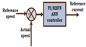
The actual speed of the motor calculated from the zero- crossing detection will be compared with the reference speed. The error will be fed to controller which processes the error and determines the reference current.
Error = Ref speed - Actual speed
Figure 8. Block diagram of speed regulator
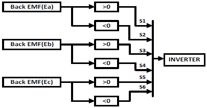
2.4.5 Current regulator
The three signals obtained from the EMF computation block will used for generating gate pulses for six switches of the inverter. The phase ‘a’ signal will be compared with zero generating gate signals for switches S1, S2. Then the phase ‘b’ signal will be compared with zero generating gate signals for switches S3, S4. Similarly phase ‘c’ signal will be compared with zero generating gate signals for switches S5, S6. There by achieving three levels at the output of the inverter with three phases.
Figure 10. PWM generation
3.1 Perturb and observe MPPT
As the source of the solar system is sun which varies for 24 hours and so the output of the solar system is also not constant. Also, there will be only one maximum power at the rated irradiance and it is required to attain maximum power to attain maximum efficiency of the system.
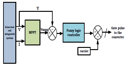
This can be only achieved with the help of tracking system known as maximum power point tracking system which operates the solar system at the maximum operating point (S.K. Saha et al., 2019). The block diagram for the maximum power point tracking system with fuzzy logic controller based distributed generation system is shown in Figure 11.
Figure 11. Block Diagram of the MPPT technique
The DC output voltage and current obtained from the solar-fuel cell integrated system will be directed to the maximum power point tracking system producing maximum power point voltage as the output of the maximum power point tracking system with certain perturbation. The maximum power point voltage will be compared with the actual output of the hybrid system which generates the error. The error between the maximum power point voltage (S. Samal et al., 2018) and actual output of the hybrid system will be then sent to the fuzzy logic controller generating the processed error. The processed error from the controller will be compared with the carrier waveform producing gate pulse for the switch of the high gain interleaved boost converter.
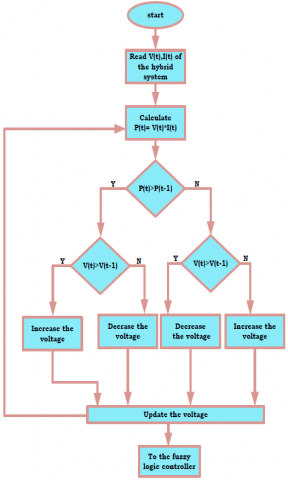
Figure 12. Flow Chart of the MPPT technique
The flow chart for the maximum power point tracking system is shown in Figure 12.
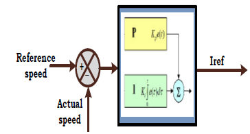
4.1 PI controller based speed controller
The comparison of reference speed with the actual speed generates error which will be directed to PI controller.
The equation for the output response from the controller can be given as
$y(t)=K_{p} e(t)+K_{i} \int e(t) d t$ (35)
Figure 13. Block diagram of PID controller
4.2 RBF ANN based speed controller
4.2.1 Radial basis function neural network
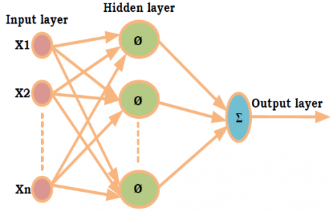
Radial basis function neural network is a type of feed forward neural network using Gaussian activation functions. They find applications in function and pattern approximations due to their excellent approximation capabilities, faster training algorithms and simpler network structure. It consists of an input layer with input neurons, hidden layer with non-linear activation functions and output layer computing outputs. The hidden layer uses a group of basis function units which performs the non linear transformation from input layer to hidden layer. So the passage of information from input layer to hidden layer is nonlinear and hidden layer to output layer if linear.
Figure 14. Connection diagram of RBF ANN
The expression for the output of jth neuron in the hidden layer can be given as
$Y_{j}=K\left(\frac{\left\|x-u_{j}\right\|}{\sigma_{j}^{2}}\right)$ (36)
Where the constant K is symmetrical function which changes from center of the neurons to zeroth position rapidly. The above expression indicates that $Y_{j}$ has a desired value only if the distance $\| x-u_{j}||$ is smaller than $\sigma_{j}$.
The output from the mth neuron in the output layer can be given as
$Z_{i}=\sum W_{i j} Y_{j}$ (37)
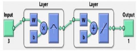
4.2.2 Flowchart and training of RBFN network
Radial basis function neural network undoes training at both the hidden layer and also at (D. Sorn et al., 2018) output layer. In general the hidden layer undergoes unsupervised learning and the output layer undergoes supervised learning with the respective target output.
Figure 15. Internal circuit of RBFN network
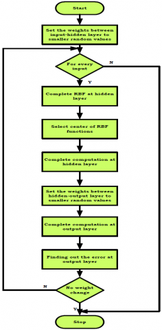
The flowchart for the training of radial basis function neural network is shown in below figure.
Figure 16. Flowchart of RBF network
The step involves in training the radial basis function neural network (X. Meng et al., 2017) is given below.
1) All the weights between the input layer and hidden layer will be initialized at smaller random values.
2) Apply inputs at the input layer and perform radial basis function computation at the hidden layer.
3) Select the centers for radial basis function form the set of input variables. Compute the computation at the output of hidden layer using the below expression.
$Y_{j}=K\left(\frac{\left\|x-u_{j}\right\|}{\sigma_{j}^{2}}\right)$
4) All the weights between the hidden layer and output layer will be initialized at smaller random values and the outputs from the hidden layer will be fed to output layer as inputs.
5) Compute the computation at the output of output layer using the below expression.
$Z_{i}=\sum W_{i j} Y_{j}$
Calculate the error between obtained output at the output layer and the target output value. Then based up on the error value, change the weights using back propagation algorithm and repeat the process until error becomes zero.
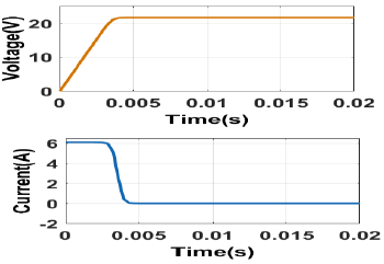
When solar irradiance passes through the solar panel, energy gets generated out of the solar panel and the Figure 17 shows the voltage and current generated by the solar panel at an irradiance of 1000w/m2.
Figure 17. Potential and Current of Solar Panel
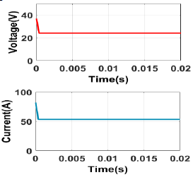
When fuel passes through the fuel stack, energy gets generated out of the fuel cell stack and the Figure18 shows the voltage and current generated by the fuel cell stack at an operating temperature of $55^{\circ} \mathrm{C}$.
Figure 18. Potential and Current of Fuel cell Stack
The output energy form the solar panel and fuel cell stack will be integrated and the output of the hybrid system is shown in Figure 19 generating voltage of around 48V.
Figure 19. Potential of Integrated System
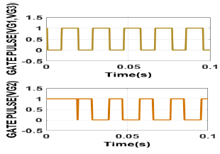
Three switches have been used in the proposed high gain interleaved boost converter such that the switches operates with the respective gate pulses attaining form the fuzzy controller based MPPT controller and the Figure 20 shows the gate pulses of the three switches.
Figure 20. Gate Pulses to HGIBC
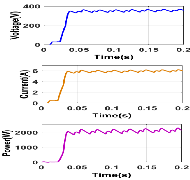
The integrated output of the solar fuel cell hybrid system has been directed to high gain interleaved boost converter and whose switches are controlled with fuzzy controller fed MPPT controller and the Figure 21 shows the voltage, current and power generated by the converter.
Figure 21. HGIBC output potential, current and energy with Fuzzy-P&O MPPT controller
5.1 with PI controller
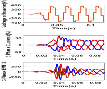
The BLDC motor has been controlled with the sensor less speed control and also the sensor less speed control has been implemented with PI controller and also with Fuzzy controller and the Figure 22 shows the voltage generated by the inverter with PI controller based speed control strategy.
Figure 22. Voltage of Inverter, Currents, EMF’s of BLDC Motor
The three-phase voltage generated by the inverter has been directed to brush less DC motor whose three phase currents and three phase EMF’s are shown in Figure 22
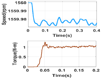
As the motor is being controlled by the sensor less control with controlling speed and torque using PI controller and the Figure 23 shows the speed and torque generated by the BLDC motor driven by PI controller based speed control technique.
Figure 23. Speed and Torque of BLDC Motor
5.2 with ANN controller
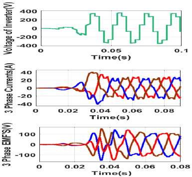
The BLDC motor has been controlled with the sensor less speed control and also the sensor less speed control has been implemented with Fuzzy controller and the Figure 24 shows the voltage generated by the inverter with fuzzy controller based speed control strategy.
Figure 24. Voltage of Inverter, Currents, EMF’s of BLDC Motor
As the motor is being controlled by the sensor less control with controlling speed and torque using fuzzy controller and the Figure 25 shows the speed and torque generated by the BLDC motor driven by fuzzy controller based speed control technique.
Figure 25. Speed and Torque of BLDC Motor
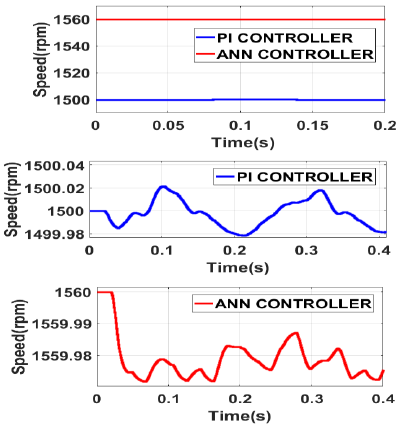
The proposed integrated system with controllers based speed controlling of BLDC has been implemented with PI and ANN controllers whose combined performance has been given with constant load torque where ANN gives better performance than PI controller in terms of speed and also in terms of torque.
5.3 With combined PI & ANN controller
Figure 26. Speed Response of BLDC Motor with PI & ANN Controllers applied constant Load Torque
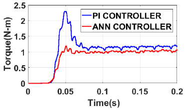
The Figure 27 shows the torque generated by the PI controller and ANN controller where the ANN controller shows the better performance than PI controller in terms of magnitude and also ripple content.
Figure 27. Torque Response of BLDC Motor with PI & ANN Controllers applied constant Load Torque
The proposed integrated system with controllers based speed controlling of BLDC has been implemented with PI and ANN controllers whose combined performance has been given with variable load torque where ANN gives better performance than PI controller in terms of speed and also in terms of torque.
Figure 28. Speed Response of BLDC Motor with PI & ANN Controllers applied Variable Load Torque
Figure 29 shows the torque generated by the PI controller and ANN controller where the ANN controller shows the better performance than PI controller in terms of magnitude and also ripple content and also PI controller provides larger peak overshoot with larger rise time.
Figure 29. Torque Response of BLDC Motor with PI &ANN Controllers applied Variable Load Torque
The proposed integrated system with controllers-based speed controlling of BLDC has been implemented with PI and ANN controllers whose combined performance has been given with zero load torque where ANN gives better performance than PI controller in terms of speed and also in terms of torque.
Figure 30. Speed Response of BLDC Motor with PI & ANN Controllers applied No Load Torque
Figure 31. Torque Response of BLDC Motor with PI &ANN Controllers applied No Load Torque
Figure 31 shows the torque generated by the PI controller and ANN controller where the ANN controller shows the better performance than PI controller in terms of magnitude and also ripple content and also PI controller provides larger peak overshoot with larger rise time.
Table 1. Output values generated by P&O-Fuzzy controller based MPPT technique
|
Parameter |
With P&O- Fuzzy based MPPT |
|
DC voltage |
370V |
|
DC current |
6.25A |
|
DC power |
2300W |
Table 1 gives the DC voltage, current and power generated by the P&O-Fuzzy controller based MPPT technique.
Table 2 shows the comparison of the proposed system with PI controller and with ANN controller with no load torque and from the table it can be concluded that the speed controller with ANN controller shows the better performance in terms of response time, overshoot, ripple content of the torque.
Table 2. Comparison table between PI controller and ANN controller-based speed control technique with no load
|
Performan ce |
Parameter |
PI controller |
ANN controller |
|
Dynamic |
Response time (ms) |
0.1 |
0.05 |
|
Overshoo t (%) |
80% |
2% |
|
|
Static |
Ripple (N-m) |
0.15 |
0.1 |
|
Efficienc y |
Output speed average value (rpm) |
1500.01 |
1559.9 |
|
Output torque average value (N-m) |
1.18 |
1.05 |
Table 3. Comparison table between PI controller and ANN controller-based speed control technique with constant load torque
|
performance |
Parameter |
PI controller |
ANN controller |
|
Dynamic |
Response time (ms) |
0.077 |
0.075 |
|
Overshoot (%) |
30% |
10% |
|
|
Static |
Ripple (N-m) |
0.11 |
0.175 |
|
Efficiency |
Output speed average value (rpm) |
1500.02 |
1559.99 |
|
Output torque average value (N-m) |
1.13 |
1.21 |
Table 3 shows the comparison of the proposed system with PI controller and with ANN controller with constant load torque and from the table it can be concluded that the speed controller with ANN controller shows the better performance in terms of response time, overshoot, ripple content of the torque.
Table 4. Comparison table between PI controller and ANN controller-based speed control technique with variable load torque
|
Performance |
Parameter |
PI controller |
ANN controller |
|
Dynamic |
Response time (ms) |
0.073 |
0.055 |
|
Overshoot (%) |
20% |
6% |
|
|
Static |
Ripple (N-m) |
0.12 |
0.176 |
|
Efficiency |
Output speed average value (rpm) |
1500.02 |
1559.99 |
|
Output torque average value (N-m) |
1.14 |
1.25 |
Table 4 shows the comparison of the proposed system with PI controller and with ANN controller with variable load torque and from the table it can be concluded that the speed controller with ANN controller shows the better performance in terms of response time, overshoot, ripple content of the torque.
Table 5. Comparison table between proposed sensor less speed control and conventional methods
|
Perfor mance |
Propo sed |
[R.S rika nth, et.al |
[Oscar- David Ramíre z- Cárden as 2020]., et.al |
[J.E.Mur alidhar 2014]., et al |
[Sant anu Mond al 2015]., et al |
|
Torque ripples (N-m) |
0.055 |
0.1 |
0.14 |
0.16 |
1.12 |
|
Speed ripples (rpm) |
0.176 |
10 |
12 |
13 |
9 |
Table 5 gives the comparison between proposed sensor less speed control technique and other existing speed control techniques where the proposed method gives better performance by 25% in terms of speed ripples and torques.
The design of electric vehicle with the utilization of renewable energy source like solar energy with the combination of fuel cell energy has been presented in this manuscript. The proposed electric vehicle drives the brush less DC motor whose speed has been monitored with the sensor less speed control technique with two types of controller's namely proportional intelligent controller and radial basis function neural network in terms of speed, torque generated, ripple content and overshoot with three test cases considering variable torque, no load torque and constant torque conditions. The RBFN shows better performance than PI controller by 30% in case of no torque condition. In case of variable load torque condition also RBFN gives 18% better performance than PI controller. The RBFN ANN shows the better performance than the PI controller by 10% in case of variable load condition and the entire analysis has been carried out using MATLAB/Simulink
[1] Rahman, M. H., Barua, K., Anis-Uz-Zaman, M., Razak, M. A., & Islam, N. (2019, March). Simulation of a Solar Power System with Fuel Cell backup Source for Hybrid Power System Application. In 2019 International Conference on Energy and Power Engineering (ICEPE) (pp. 1-4). IEEE.
[2] Obaid, W., Hamid, A. K., & Ghenai, C. (2019, April). Wind-Fuel-Cell-Solar Hybrid Electric Boat Power Design with MPPT System. In 2019 8th International Conference on Modeling Simulation and Applied Optimization (ICMSAO) (pp. 1-5). IEEE.
[3] Khurshid, O., Saher, S., & Qamar, A. (2019, July). Power Generation by Hybrid Approach Solar PV/battery Power/hydrogen Generation/fuel Cell. In 2019 International Conference on Electrical, Communication, and Computer Engineering (ICECCE) (pp. 1-4). IEEE.
[4] Patil, R. (2017, August). Fuzzy based MPPT technique for PV system. In 2017 International Conference on Energy, Communication, Data Analytics and Soft Computing (ICECDS) (pp. 1455-1459). IEEE.
[5] Saha, S. K. (2018, July). Optimization Technique Based Fuzzy Logic Controller for MPPT of Solar PV System. In 2018 International Conference on Emerging Trends and Innovations In Engineering And Technological Research (ICETIETR) (pp. 1-5). IEEE.
[6] Kumar, R., Kumar, B., & Swaroop, D. (2018, September). Fuzzy Logic based Improved P&O MPPT Technique for Partial Shading Conditions. In 2018 International Conference on Computing, Power and Communication Technologies (GUCON) (pp. 775-779). IEEE.
[7] Samal, S., Barik, P. K., & Sahu, S. K. (2018, March). Extraction of maximum power from a solar PV system using fuzzy controller based MPPT technique. In 2018 Technologies for Smart-City Energy Security and Power (ICSESP) (pp. 1-6). IEEE.
[8] Reddy, K. J., & Sudhakar, N. (2018). High voltage gain interleaved boost converter with neural network based MPPT controller for fuel cell based electric vehicle applications. IEEE Access, 6, 3899-3908.
[9] Sreeram, K. (2018, March). Design of fuzzy logic controller for speed control of sensorless BLDC motor drive. In 2018 International Conference on Control, Power, Communication and Computing Technologies (ICCPCCT) (pp. 18-24). IEEE.
[10] Reshma, K. M., & Isha, T. B. (2018, March). A Back-EMF Based Sensorless Speed Control of Four Switch BLDC Motor Drive. In 2018 International Conference on Control, Power, Communication and Computing Technologies (ICCPCCT) (pp. 283-287). IEEE.
[11] Kroics, K., Zakis, J., & Sirmelis, U. (2017, October). Implementation of the back EMF zero crossing detection for BLDC motor. In 2017 IEEE 58th International Scientific Conference on Power and Electrical Engineering of Riga Technical University (RTUCON) (pp. 1-4). IEEE.
[12] Štulrajter, M., Makyšsn, P., & Rafajdus, P. (2017, September). Sensorless control of high speed BLDC. In 2017 IEEE International Symposium on Sensorless Control for Electrical Drives (SLED) (pp. 225-230). IEEE.
[13] Murali, M., & Sreekanth, P. K. (2018, March). A Novel Method for the Torque and Current Ripple Minimization of BLDC Motor Using Phase Voltage Method. In 2018 International Conference on Control, Power, Communication and Computing Technologies (ICCPCCT) (pp. 273-277). IEEE.
[14] Syamsiana, I. N., Wang, M. S., & Sumari, A. D. W. (2019, October). A Study on Sensorless Trapezoidal BLDC Motors Based on Back-EMF Zero Crossing Detection Method. In 2019 2nd International Conference on Applied Engineering (ICAE) (pp. 1-6). IEEE.
[15] Allam, S. M. (2019, December). Performance Analysis and Enhancement of a PV Fed Sensorless BLDC-Motor for an Efficient Water-Pumping System. In 2019 21st International Middle East Power Systems Conference (MEPCON) (pp. 776-783). IEEE.
[16] Chen, S. C., & Kuo, C. Y. (2017, May). Design and implement of the recurrent radial basis function neural network control for brushless DC motor. In 2017 International Conference on Applied System Innovation (ICASI) (pp. 562-565). IEEE.
[17] Ho, T. Y., Chen, Y. J., Chen, P. H., & Hu, P. C. (2017, May). The design of a motor drive based on neural network. In 2017 International Conference on Applied System Innovation (ICASI) (pp. 337-340). IEEE.
[18] Darong, S. O. R. N., & Chen, Y. (2018, May). Design optimization of Permanent Magnet Brushless Direct Current Motor using Radial Basis Function Neural Network. In 2018 IEEE 7th Data Driven Control and Learning Systems Conference (DDCLS) (pp. 38-43). IEEE.
[19] Srikanth, R., Venkatesan, M., & Subba Rao, M. (2020). Design and performance evaluation of PID, Fuzzy logic and ANN controllers based MPPTs for hybrid electric vehicle applications. International Journal of Ambient Energy, 1-15.
[20] Chen, X., Li, H., Sun, M., & Liu, G. (2018, October). Sensorless commutation error compensation of high speed brushless DC motor based on RBF neural network method. In IECON 2018-44th Annual Conference of the IEEE Industrial Electronics Society (pp. 683-688). IEEE.
[21] Xu, H., Xu, L., Chen, S., Liu, J., Cheng, G., Liang, X., & Mao, W. (2020, October). Brushless DC motor Control System Based on RBF Neural Network. In 2020 IEEE International Conference on Mechatronics and Automation (ICMA) (pp. 1704-1709). IEEE.
[22] Meng, X., Rozycki, P., Qiao, J. F., & Wilamowski, B. M. (2017). Nonlinear system modeling using RBF networks for industrial application. IEEE transactions on industrial informatics, 14(3), 931-940.
[23] Muralidhar, J. E., & Aranasi, P. V. (2014, March). Torque ripple minimization & closed loop speed control of BLDC motor with hysteresis current controller. In 2014 2nd International Conference on Devices, Circuits and Systems (ICDCS) (pp. 1-7). IEEE.
[24] Mondal, S., Mitra, A., Chowdhury, D., & Chattopadhyay, M. (2015, February). A new approach of sensorless control methodology for achieving ideal characteristics of brushless DC motor using MATLAB/Simulink. In Proceedings of the 2015 Third International Conference on Computer, Communication, Control and Information Technology (C3IT) (pp. 1-4). IEEE.
[25] Ramírez-Cárdenas, O. D., & Trujillo-Romero, F. (2020). Sensorless speed tracking of a brushless DC motor using a neural network. Mathematical and Computational Applications, 25(3), 57.