Antony Prabu D.* | Subbaiah K.
© 2021 IIETA. This article is published by IIETA and is licensed under the CC BY 4.0 license (http://creativecommons.org/licenses/by/4.0/).
OPEN ACCESS
The present work reports about the effect of cast scandium doped ER5356 filler rod in Tungsten Inert Gas welding of dissimilar Aluminium Magnesium alloys. The grain refinement effect on weld microstructure by transition metal scandium was investigated with optical and scanning electron microscope. Additionally, XRD analysis, tensile strength (global and component joint) and microhardness were tested on weld samples. The microstructural examination in weld fusion zone observed fine grain size and suppressed dendrite arm spacing. The formation of Al3Sc precipitate in weld fusion zone due to scandium inclusion in filler was identified and resulted in improving the weld strength significantly. The higher joint efficiency of 92.5% was achieved in the global joint of weld samples. The failure location of global joint tensile samples identified the weld fusion zone is stronger than AA5052 base material. Further weld strength was evaluated with component joint by micro tensile test, which results in 70MPa enhancement in UTS values and validating the accurate weld strength. However, the elongation of the tensile test sample reduced marginally for the weld. The fracture mechanism of the weld joint observes decrease in ductility. The significant increase in hardness of the weld fusion zone was evident due to doping of scandium compared to the other zones of the weld.
Al-Mg alloys, Mechanical properties, Microstructures, Scandium, TIG Welding
Aluminium alloys are among the lightweight material which has excellent properties and high strength to weight ratio resulting as better alternative for replacing heavy materials [1]. Among the different Al alloys available, AA5052-H32 [2] and AA5083-H111 [3] are used in various industries such as marine, aerospace, desalination plants and automotives as plates, structural parts, fuel tanks, welded structures etc which demands for good weldability and mechanical properties. Hence an attempt is made to fabricate these two different Al Mg alloys. AA5083 being a high strength alloy comparatively costlier than AA5052-H32 being medium strength alloy. Therefore, joining of these alloys has become vital depending on the industrial needs where AA5083 can be replaced with AA5052 when the requirement is for less strength and cost reduction. Among different joining methods available, TIG welding is a low-cost option which requires less human effort. When joining materials with TIG welding, loss of strength and inferior mechanical properties than the parent material are expected [4]. Selection of suitable filler material plays a significant role in altering the physical, chemical, and metallurgical properties in fabricating strong welds. From previous works, it is found that ER5356 filler is suitable for TIG welding similar and dissimilar grades of 5xxx and 6xxx Al alloys resulting in better mechanical properties and strength to the weld [5]. Further to improve the strength of the TIG weld joint, grain refinement of the weld is focused. The Al-Mg alloys derive its strength from solid solution strengthening, precipitation strengthening and grain size strengthening [6-7].
An effective method to improve the strength of Al alloys and Al welds is by addition of Scandium (Sc), a potential grain refiner. Scandium addition on Al alloys was patented by Willey in 1971 [8]. Addition of Sc to Al alloys results in formation of coherent strengthening particles and acts as a potential grain refiner. The Sc efficiently combines with Al and forms Al3Sc precipitate which can significantly improve the strength [9-10]. Similar result was documented recently for Erbium alloying, a grain refiner from the works of Y. Wang et.al [24]. Aluminium 5052 alloy when doped with scandium result in formation of Al3Sc precipitate which is responsible for the precipitate strengthening of the alloy [11]. Similarly, AA5083 alloy doped with Sc improves the mechanical properties due to reduction of dendritic arm spacing [12].
Even though scandium is considered as most effective in enhancing the welding properties of Al-Mg alloys, when related to the cost involved with association of Sc, instead of alloying Sc with base Al-alloy, it can be added in the filler rod to minimize the consumption and improve the weld strength [5]. Many researchers have reported that filler material influence the properties of the welded joint and their microstructures. When 0.5wt% Sc modified filler rod used for TIG welding AA6061 alloy, it resulted in best pitting corrosion resistance and better properties [13]. When aluminium 7000 series was welded with Sc added filler, it shows significant grain refinement and good mechanical properties [14]. Appreciable enhancement of TIG weld FZ mechanical properties were observed due to Sc doping 2319 filler to TIG weld Al-6.5%Cu alloy [15]. AA6082 was TIG welded with Sc modified Al-4Si and Al-5Mg fillers resulted in improved joint strength [16]. TIG welding of AA5083 with Sc modified ER4043 filler rod with different compositions of Sc results in grain refinement at FZ in due course improving the mechanical characteristics of weld [17]. From the literature’s reviews and up to authors knowledge, it is observed that TIG welding with scandium doped ER5356 filler rod for the combination of dissimilar AA5052-H32 and AA5083-H111 alloys were not tried so far. An attempt has been made to document the effect of 0.5wt%Sc addition to ER5356 filler rod for welding the above-mentioned alloy combination. Grain refinement at the weld fusion zone and enhancement of mechanical property due to addition of scandium with ER5356 filler rod were correlated. Optical microstructures, scanning electron microstructures, micro hardness graph, fractography, X-Ray diffraction (XRD) and joint efficiency of weld are studied.
The base materials used are AA5052-H32 (5mm thick) (Mg 2.48%, Fe 0.388%, Si 0.092%, Mn 0.071%, Cu 0.092%, Cr 0.193%, Ti 0.03%, Zn 0.008%, Al balance (weight fraction) and AA5083-H111 (5mm thick) (Mg 4.254%, Fe 0.259%, Si 0.980%, Cu 0.346%, Cr 0.113%, Zn 0.103%, Ti 0.019%, Zr 0.002%, Al balance (weight fraction). The mechanical properties of the BM are presented in Table 1.
Table 1. Base Material property
$\begin{array}{|c|c|c|c|}\hline \text { Base Material, (BM) } & \text { UTS, MPa } & \text { YS, MPa } & \text { (% EI) } \\\hline \text { AA5052-H32 } & 231.00 & 192 & 22.00 \\\hline \text { AA5083-H111 } & 321.2 & 260 & 22.16 \\\hline\end{array}$
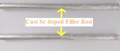
The modified Sc doped cast filler rod (0.5wt% Sc) is fabricated by adding specific proportion of master alloy (Al-2 wt%Sc) to ER5356 filler rod whose chemical composition is (Mg 4.5-5.5%, Fe 0.4%, Si 0.25%, Ti 0.06-0.2%, Mn and Cr 0.05-0.2%, Zn and Cu 0.1%, and Al balance (weight fraction)). The filler rod is casted by melting the constituents in electrical resistance furnace and solidified into cylindrical rods of 10 mm diameter and 200 mm length as shown in Fig 1. The cast rods are machined to 2.4 mm diameter for feasibility during welding process.
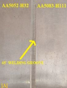
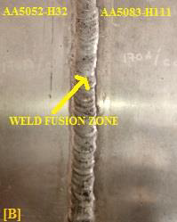
The constant current TIG welding was performed to make dissimilar single side butt joint by placing AA5052-H32 and AA5083-H111 together. Since TIG welding is symmetric process in nature, plates can be arranged on any side. Base materials are machined to 45̊ groove on one corner as shown in Fig 2a. Prior to welding, the BM and filler rods were thoroughly cleaned. Full penetration weld in plates were successfully produced. The welding parameters and filler material selection strongly influences the mechanical behavior of the welded joints. In this work, the input process parameter chosen for TIG welding are 16V voltage, 170Amps current, 150mm/min weld travel speed, 2.4mm filler diameter and 11lit/min shielding gas flow rate. To prevent the defects in the welded samples, pure argon shielding gas is selected.
Figure 1. Fabricated Cast Scandium doped filler Rod.
The standard experimental procedure is followed to identify the mechanical and micro structural characterization of welded joints. The optical and scanning electron microstructure characterizations are utilized, to identify defects formed in welded joints. ASTM E293-11 standard was used for metallurgical characterization.
Before testing, the samples are polished using emery sheet and disc polishing method, followed by Keller’s etchant process. The microstructural characterization is performed to identify the behavior of grain structure in different locations of welded samples. The mechanical characterization such as hardness and tensile test are evaluated. The ASTM E384-11e1 standard was executed for vicker's micro-hardness test. The experiment process is performed under 1 kg load and 15 sec dwell time during hardness testing. For tensile test sample ASTM E8M global joint and component part joint standards were followed. The input variables for tensile test experiments are 40kN axial load and 0.2mm/min strain rate. X-Ray Diffraction analysis (XRD) is used to identify the presence of Al3Sc precipitate.
(a) Before welding
(b) After welding
Figure 2. Specimen images
3.1 Macrostructure and Optical Microstructures
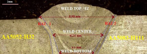
The weld macrostructure image is shown in Fig 3 confirms the full penetration has achieved. The FZ and heat affectedzone (HAZ) on either side shows no evidence of cracking. Improper usage of weld consumables and excess heat input during welding can lead to cracking in weld FZ. Since there are no crack defects in the weld, the parameters used are satisfactory to obtain defect-free welds.
The images of the weld fabricated reveals consistent bead structure with good interface. The boundaries of the weld have smooth transition on either side of the BM. The HAZ of 5052 is broader than the HAZ of AA5083. The coarsening of grains are distinct at weld FZ compared to both BM. Acceptable bead height, bead width and full depth of penetration are visible. The bead widths of weld FZ at different locations are shown in Fig 3.
Figure 3. Macrostructure of weld joint
Figure 4. Optical microstructure of Base Materials. a. AA5052-H32; b. AA5083-H111
Fig 4a and b shows the OM of AA5052-H32 processed to strain hardened condition and AA5083-H111 processed to sensitized and stabilized conditions respectively.
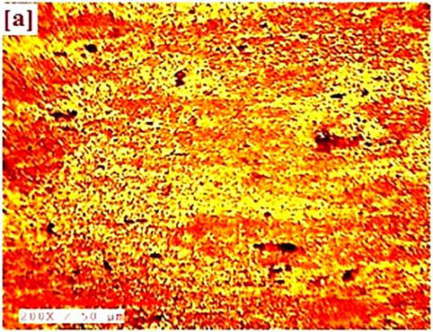
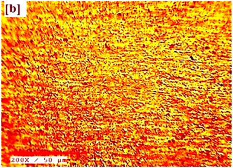
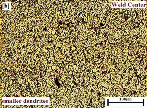
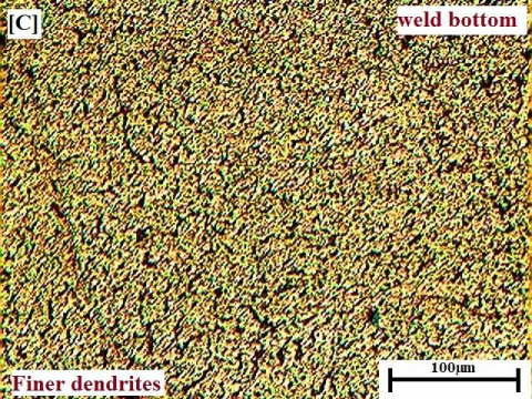
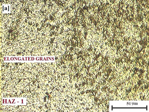
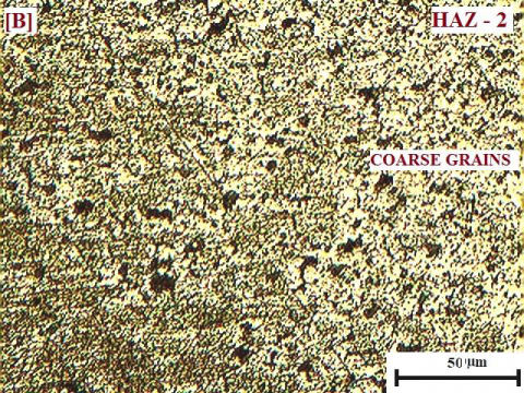
The microstructures of FZ locating weld top, weld center, and weld bottom region are shown in Fig 5a, Fig 5b, and Fig 5c respectively. The HAZs on either side of the weld are shown in Fig 6a and 6b. At HAZ–1 and HAZ-2 the grain coarsening is clearly visible. From the grain size visualized in the BMs compared to FZ of weld, significant reduction is observed, and grains are densely nucleated. The suppression of dendrite arm spacing was also recognized on weld FZ.
Figure 5. Optical microstructure of FZ. a. Weld top; b. Weld center; c. Weld bottom
The average dendrite sizes in three different locations of FZ in weld top, center and bottom were measured about 8μm, 5μm and 4μm respectively. The minor variation in average grain size is due to change in rate of heating and cooling during welding. Weld top region experiences fast heating and rapid cooling which results in formation of coarse dendrites. Whereas FZ bottom region experiences slow heating and cooling results in forming fine dendrites. Generally, in TIG welding, coarse dendrites are formed in FZ which is associated to poor mechanical properties.
Figure 6. Optical microstructure of HAZ. a. HAZ-1; b. HAZ -2
From the optical microstructure images of FZ it is evident that the addition of scandium in filler effected the refinement of the grains, throughout the weld region. Therefore, grain refinement has supported the superior mechanical properties of the joint. Similar results have been made by earlier researchers with enhanced properties due to fine dendrites formation related to Sc addition in Al-Mg alloy [12, 17].
3.2 SEM microstructures
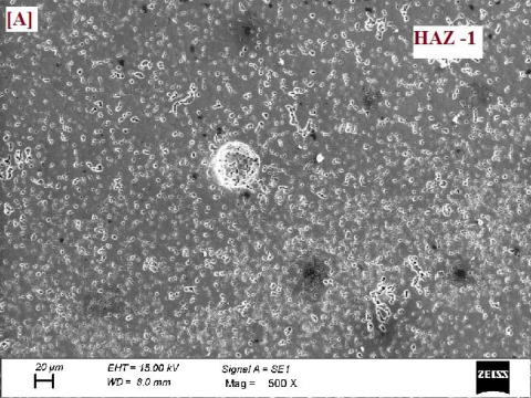
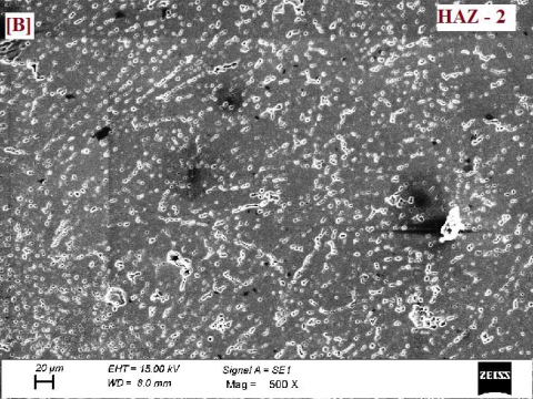
The SEM microstructures of AA5052-H32 shows partially recrystallized microstructure due to insufficient stabilizing process followed by cold rolling can be seen in Fig 7a. The SEM image of AA5083-H111 is shown in Fig 7b with strain hardening characteristics resulting in arranged and elongated grains in rolling direction. The Al3Mg2 precipitates are visible in grain boundaries. Mn and Fe rich particles are also visible in microstructures. The HAZ-1 and HAZ-2 are shown in Fig 8a and Fig 8b respectively. The FZ of weld visualizes relatively very fine grains and discontinues eutectic due to addition of grain refiner scandium which is shown in Fig 9. Similar grain refinement behavior is reported due to addition of Sc in ER4043 filler rod and TIG welding AA6061 alloy [13]. The weld microstructure at the weld FZ shown in Fig 9 is like Chinese script and the distribution is uniform. These fine dendrites are responsible for higher mechanical properties of the weld joint. A similar SEM image structure is reported from the works of Srinivasa Rao Mallipudi et al [18].
Figure 7. SEM microstructures of BM. a. AA5052-H32; b. AA5083-H111
Figure 8. SEM microstructures of a. HAZ-1; b. HAZ-2
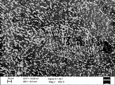
Figure 9. SEM microstructure of TIG weld FZ fabricated by Sc doped filler rod
3.3 XRD analysis pattern at the weld FZ
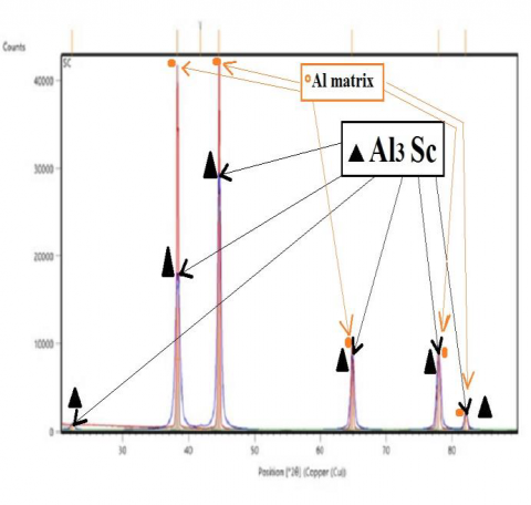
The intermetallic formed in weld FZ are shown in Fig 10. The presence of Al3Sc particles was identified using XRD phase analysis, confirming the reason for enhancement of mechanical properties. Similar results were identified for AA6061 alloy TIG welds with modified ER 4043/0.5wt%Sc filler [13].
Figure 10. XRD pattern of weld 2
3.4 Chemical composition at weld FZ and influence of magnesium
The chemical compositions of alloying in weld FZ are shown in Table 2. The magnesium present at the weld FZ results in solid solution strengthening and precipitate strengthening effect from the formation of Al3Mg2 [6]. The ferrous and manganese will form intermetallic such as Al6 (Fe, Mn) and Mg2Si, which may help in enhancing mechanical properties of the weld [3]. With the presence of scandium in weld FZ, formation of Al3Sc precipitate was identified using XRD analysis as shown in Fig 10. Identical results were found from the work of Ramanaiah et al (2012) [13].
Table 2. Chemical Composition of the weld FZ (% by weight)
$\begin{array}{|c|c|c|c|c|c|c|c|c|c|}\hline \text { Process } & \mathbf{M g} & \mathbf{M n} & \mathbf{F e} & \mathbf{S i} & \mathbf{T i} & \mathbf{C r} & \mathbf{C u} & \mathbf{S c} & \mathbf{A l} \\\hline\begin{array}{c}\text { TIG } \\\text { weld }\end{array} & 4.27 & 0.12 & 0.19 & 0.19 & 0.03 & 0.09 & 0.36 & 0.5 & \mathbf{B a l} \\\hline\end{array}$
3.5 Tensile properties
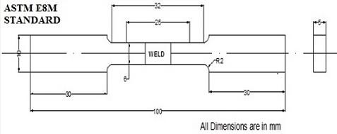
The dimensions of specimens (large sample) with ASTM E8M standard are mentioned in Fig 11. The tensile samples of Scandium doped filler weld failed at AA5052-H32 side and the TIG weld joint with ER5356 filler (commercial filler) failed at the weld FZ. The weld area is intact for Sc doped weld and confirms the weld is stronger more than weaker BM.
Table 3. Tensile properties of Global joint (large sample) of TIG weld samples
|
Process |
FILLER ROD |
UTS, MPa |
% EI |
Fracture location |
|
TIG |
Commercial filler (ER5356 filler) |
192.5 |
20 |
Weld |
|
Scandium doped filler |
214.5 |
16.75 |
AA5052-H32 |
The joint efficiency of Sc doped weld is 92.86% with reference to weaker BM. The reduction in ductility of weld with respect to the weaker BM is 23.86%. The fracture pattern of global joint samples shows formation of necking outside the FZ indicating the failure mode is ductile. Such similar result was reported in cast Al–Mg alloy with 0.17wt%Sc [19]. The enhanced joint efficiency is due to the finer dendrites formed by doping scandium to the weld FZ. Similar observations were made on AA5083 alloy, with addition of Sc shortening the dendrite arm spacing and resulting in enhanced UTS [12].
Figure 11. Tensile sample with ASTM E8M standard (Global joint)
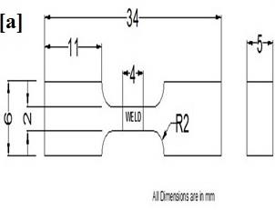
Considering the tensile failure occurring outside the weld FZ at weaker BM, the need to evaluate the strength of the weld FZ using component part joint (small sample) was required and the samples are shown in Fig 12.
Figure 12. Tensile sample of component part joint
The samples are machined from the weld fusion zone. Similar inspection method used for testing large sample is also followed for small sample. The weld strength of Al-Mg-Sc alloy joined with FSW process was determined from smaller specimen, by Lapasset et al in 2003 [20]. The values of component part joints strength are listed in Table 4.
Table 4. Tensile properties of Component part joint (small sample) for Sc doped TIG weld
$\begin{array}{|c|c|c|c|c|}\hline \text { Process } & \text { FILLER ROD } & \begin{array}{c}\text { UTS, } \\\text { MPa }\end{array} & \begin{array}{c}\% \\\text { EI }\end{array} & \begin{array}{c}\text { Fracture } \\\text { location }\end{array} \\\hline \text { TIG } & \begin{array}{c}\text { Scandium doped } \\\text { filler }\end{array} & 304.3 & 12.66 & \begin{array}{c}\text { Weld metal } \\\text { (FZ) }\end{array} \\\hline\end{array}$
The tested samples of component part joints are shown in Fig 12. An UTS value of 304.3MPa was recorded proving the exact strength of the weld FZ. The enhancement of weld strength was 132.6% with an improvement of 73MPa was reported. According to Hall- Petch equation, fine grains and dendrites results in improvement of UTS. The presence of scandium at weld FZ results in grain refinement and leads to the formation of Al3Sc, which additionally improves the strength of the weld. The fracture pattern of the component part joint sample was shear failure, exactly at the center of the weld with failure intersection angle of 45̊. Identical fracture pattern was reported, to evaluate weld FZ in which weld nugget of cast Al-Mg-Sc alloy was completely intact [21]. Therefore, Sc refines the grain size in the weld FZ, which results in strengthening of the joint based on Hall-Petch effect [22-23].
3.6 Hardness survey
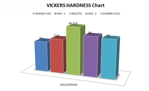
The hardness measurement was taken along the cross section in transverse direction parallel to the weld surface and BM is shown in Fig. 13. The average BM hardness was also plotted in this graph. The average hardness of weld FZ was identified as 99.32 Hv1. From the hardness survey, noticeable increase in hardness was found particularly at the weld FZ region with maximum value of 104Hv1. The hardness values at AA5052-H32 side of weld are similar to the corresponding base material hardness. Whereas at the AA5083-H111 side of the weld, hardness value is higher i.e., 90Hv1 compared to the corresponding base material. The increase of hardness in FZ is due to grain refinement caused by Sc and formation of Al3Sc precipitates. Similar hardness increment had been reported earlier, with addition of 0.5wt% Sc to AA5083 TIG weld joints [17]. The intermetallic formed at weld FZ attributes the increased hardness. From previous work of TIG welding AA5083-H111 with ER5356 filler rod, the hardness in FZ was governed by the formation of intermetallic compounds such as Al6(Fe, Mn), Mg2Si [3]. Additionally, Al3Sc plays a major role of hardness enhancement in the weld FZ. Also, fine dendrites formed at weld FZ enhance the hardness. Commonly the fracture locations are governed by hardness, so the lowest hardness region is most vulnerable to fracture. Hence the joint failed at AA5052-H32 side because of its minimum hardness (64Hv1) in the region.
Figure 13. Comparison of Hardness at different zones of the weld
3.7 Fractographic studies
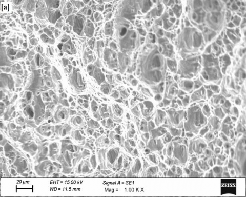
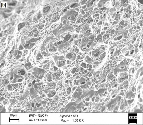
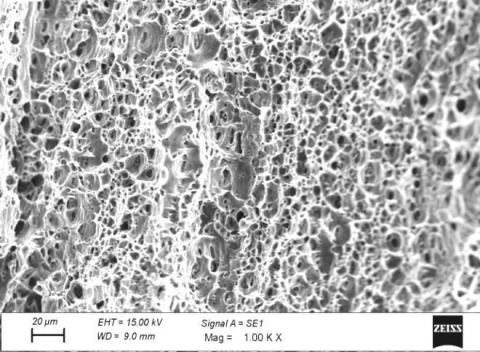
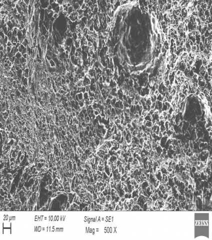
The SEM fractography of base metals are shown in Fig 14a and Fig 14b, subjected to tensile test clearly indicates large dimples, with cavities of different size resulting in ductile mode of failure which is common in Al alloys. The SEM fractography of the weld joint is shown in Fig 15. In fracture surface it is visible that dimples are finer; hence the mode of failure is ductile. There was no evidence of any defects, and the fracture was ductile. Hence the base material characteristics are retained, which shows the fracture is at the base material with lowest hardness. Similar observations were made earlier in AA5083 alloy TIG weld with Sc added filler [17]. The fractography of the weld prepared with ER5356 filler is observed in Fig 16 clearly shows the failure location at the FZ with weld defects.
Figure 14. Fractographs of BM a AA5052-H32; b AA5083-H111
Figure 15. Fractographs of Sc doped weld
Figure 16. Fractographs of weld with commercial filler (ER5356)
The Aluminium alloys AA5052-H32 and AA5083-H111 were successfully joined using TIG welding with 0.5%wt. Sc added ER5356 filler rod. The influence of scandium on the microstructures and mechanical behavior were investigated. The main conclusions discussed are as follows:
The results obtained by optical microstructures and scanning electron microstructures shows formation of fine dendrites and significant reduction of grain size at weld fusion zone, due to addition of Sc and associated with enhanced mechanical properties. The UTS for weld joint is 304.3 MPa, whereas the 5052 alloy has 231.MPa, so 32% enrichment in UTS due to addition of scandium to the weld. This leads to superior TIG weld fusion zone behavior than 5052 alloy. The increment of tensile strength in the weld is due to strengthening mechanisms, such as grain refinement, solid solution strengthening by Mg and precipitate strengthening by Al3Sc intermetallic. The average hardness increase of 67% was notable at weld fusion zone when compared to 5052 base material. The formation of Al3Sc particles and grain refinement supports the improved hardness at the weld fusion zone. The superior average hardness of 104 Hv1 was recorded in the weld FZ.
[1] Manladan, S.M., Yusof, F., Ramesh, S. (2017), “A review on resistance spot welding of aluminum alloys”, Int J Adv Manuf Technol, 90, 605–634. http://doi.org/
[2] Mustafa, U., Chandra, M. & Paulraj, S. (2018), “Influence of Filler Wire Diameter on Mechanical and Corrosion Properties of AA5083-H111 Al–Mg Alloy Sheets Welded Using an AC Square Wave GTAW Process”. Trans Indian Inst Met., 71, 1975–1983.
[3] Koteswara Rao, Sajja & Reddy, G. & Rao, K. & Rao, P Srinivasa Rao & Kamaraj, M. & Kalvala, Prasad. (2004), “Gas tungsten arc welded AA 2219 alloy using scandium containing fillers - Mechanical and corrosion behavior”. Transactions of the Indian Institute of Metals, 57. 451-459.
[4] Luijendijk, T,(2000), “Welding of dissimilar aluminium alloys. Journal of Materials Processing Technology”. J MATER PROCESS TECHNOL, 103. 29-35.
[5] Kendig, K.L. & Miracle, Dan, (2020), “Strengthening mechanisms of an Al-Mg-Sc-Zr alloy”, Acta Materialia, 50. 4165-4175.
[6] C.B. Fuller, M.W. Mahoney, (2006), “The effect of friction stir processing on 5083-H321/ 5356 Al arc welds: microstructural and mechanical analysis”, Metall. Mater. Trans. A, 37a 3605–3615.
[7] Willey, L.A, (1971). United States Patent No. 3,619,181.
[8] Sawtell, R.R., Jensen, C.L,(1990), “Mechanical properties and microstructures of Al-Mg-Sc alloys” . Metall and Mat Trans A, 21, 421–430.
[9] Filatov YuA, Yelagin VI, Zakahrov VV, (2000), “New Al–Mg–Sc alloys”, Mater Sci Eng A , 280:97–10.
[10] Ahmad, Z., Jabbar, A.A.B., Abdullahi, K., Abbas, M , (2011), “Effect of scandium doping on the corrosion resistance and mechanical behavior of Al-3Mg alloy in neutral chloride solutions”, Mater. Sci. Appl. 2, 244–258.
[11] A. Tadashi, S. Nobutaka, M. Yasuhiro, (2000), “The effect of scandium on the as-homogenized microstructure of 5083 alloy for extrusion”, Mater. Sci. Eng. A, 280, pp. 139-145.
[12] Ramanaiah, N., Prasad Rao, K, (2013), “Effect of modified AA4043 filler on corrosion behavior of AA6061 alloy GTA welds”, Int J Adv Manuf Technol, 64, 1545–1554.
[13] Norman A, Birley S, Pragnell P, (2003), “Development of New High strength Al-Sc Filler Wires for Fusion Welding 7000 series Aluminium Aerospace Alloys”, Sci. Technol. Weld. Joining, Vol 8 No4. pp 235-345.
[14] Babu, N. & Talari, Mahesh & Pan, D. & Wei, J, (2012), “High-temperature mechanical properties investigation of Al-6.5 % Cu gas tungsten arc welds made with scandium modified 2319 filler”. The International Journal of Advanced Manufacturing Technology, 65.
[15] Babu, N. & Talari, Mahesh & Pan, D. & Sun, Z. & Wei, J. & Katakam, Sivaprasad, (2012),“Microstructural characterization and grain refinement of AA6082 gas tungsten arc welds by scandium modified fillers”. Materials Chemistry and Physics. 137. 543–551.
[16] Babu, N. & Bhikanrao, Patil & Katakam, Sivaprasad. (2013), “Enhanced Mechanical Properties of AA5083
GTA Weldments with Current Pulsing and Addition of Scandium”. Materials Science Forum. 765. 716-720.
[17] Mallipudi, S., Nallu, R, (2019), “Effect of Scandium and Zirconium Additions on Mechanical Properties of Al–Mg–Mn Alloy”. Trans Indian Inst Met, 72, 227–238.
[18] Lathabai. S, and Lloyd, P.G. (2002), “The effect of scandium on the microstructure, mechanical properties and weldability of a cast Al-Mg alloy”. Acta Materialia, Volume 50, Issue 17, Pages 4275-4292.
[19] Lapasset, G., Girard, Y., Campagnac, M.H., Bolvin, D, (2003), “Investigation of the microstructure and properties of a Friction stir welded Al-Mg-Sc alloy”. Mater. Sci. Forum. 426–432, 2987– 2992.
[20] Subbaiah, K. & Manivasagam, Geetha & M, Govindaraju & Koteswara Rao, Sajja. (2013). “Tensile properties and microstructure of Friction Stir welded cast Al-Mg-Sc aluminum alloy”. Materials Science and Technology Conference and Exhibition, MS and T 2013. 3. 2126-2132.
[21] Hall EO. (1951). Proc Phys Soc B 64:747–752 3.
[22] Petch NJ. (1953). J Iron Steel Inst 174:25–28.
[23] Wang, Yichang & Wu, Xiaodong & Cao, Lingfei & Tong, Xin & Couper, Malcolm & Liu, Qing.(2020) “Effect of trace Er on the microstructure and properties of Al–Zn–Mg–Cu–Zr alloys during heat treatments”. Materials Science and Engineering: A. 792. 139807.