Mohamad Iqhmannabil Karim | Azrul Azim Abdullah Hashim | Nor Maniha Abdul Ghani*
© 2022 IIETA. This article is published by IIETA and is licensed under the CC BY 4.0 license (http://creativecommons.org/licenses/by/4.0/).
OPEN ACCESS
Flexible manipulator is widely used in the implementation of industial robotic due to its advantages such as low weight, low power consumption, higher load capacity, high-speed operation, small actuators and low production costs. However, the position and speed of flexible manipulator system are very difficult to control due to the tip vibration that result in degradation of performance. Modelling and control of a double-link flexible robot manipulator are presented in this study. Controlling the movement of a double-link manipulator, on the other hand, has proven to be a challenging task, especially when a flexible framework is used. Moreover, most double-link flexible manipulator system models are not developed based on real hardware. Hence, this project aims to develop a Solidworks design for double link flexible robotics manipulator (DLFRM) as well as a real hardware prototype. The control position performance of DLFRM was analyzed, and the controllers were tested on a hardware prototype. This project started with a simulation of both controllers, which are PID and FLC. The simulation was designed in Solidworks and exported to Simulink and then converted as Simscape. Then, the hardware for each controller was validated using the control parameter in the simulation. The joints for the robot manipulator were designed in Solidwork and built using 3D printing.
Double Link, Fuzzy Logic Control, PID Control, Simscape, Solidworks
Robotic manipulators constitute a significant component in the manufacturing industry. They are used for many reasons, including speed, accuracy, and repeatability [1]. A robotic manipulator arm is a programmable electronic and multipurpose mechanical device that performs a wide range of function by manipulating materials, components, objects, or tools through predetermined movements. Formerly, robotic manipulator designs were huge and heavy, resulting in the inflexible arm and stiff joint designs. As a result, their use is restricted to light weights, and their movement is limited. Hence, the traditional design is unfavorable in today’s sectors since it is inefficient in terms of speed, productivity, and power consumption. Furthermore, lighter construction has become a prerequisite for every engineering system. Hence, to overcome the problem, a flexible manipulator was composed.
There are numerous control systems available to control the manipulators. According to previous studies, the most common method to control the flexible manipulator is the PID control, which is used to regulate the motion of the flexible manipulators and also to track the set-points [2]. Another method to control the flexible manipulator has also been implemented in another study, FLC. In controlling nonlinear systems, the approach of Fuzzy logic has been well recognized with its systematic capability to include human linguistic knowledge in the controller design [3].
Most model of double link flexible manipulator system is not developed based on real hardware. The model is developed merely based on simulation. The mathematical dynamics are sometimes neglected, and there are nonlinearities, thus not representing the real system. According to a previous paper, the flexibility of the flexible manipulator model will be compromised if all nonlinear components are disregarded [4]. The flexible manipulator is considerably challenging to control and operate compared to their rigid counterparts due to their flexibility. This issue has become particularly prevalent in the field of space and industrial robots with light and flexible linkages. The flexible manipulators, however, lead to vibration on the robot controllers. The flexible manipulator system results in low accuracy and low precision of the system. Hence, the low accuracy of the system may affect the effectiveness of the robot controller. Flexible manipulators can be difficult to manipulate in order to obtain and maintain precise positioning.
There are various methods were proposed to compare the techniques for the control system of flexible manipulator system in terms of the rise time, settling time, and overshoot. According to work done in [4-6], a controller was created by utilizing the set-point & suitable tuning of the P, I, & D values so that the tracking is done with the least amount of error, as can be seen from the output simulated results.
Fuzzy logic was implemented and showed a better result in flexible manipulators [7]. In the study, using the FLC method to control the flexible manipulator, fast trajectory tracking and precise position were obtained. It also showed that the FLC was able to suppress the vibration in a shorter time, which was 2 seconds. The performance analysis of PID PD and Fuzzy Controller for position control of 3-DOF robot manipulator was presented [8]. According to their findings, PID and PD controllers outperformed FLC based on the rise and settling times. However, in terms of overshoot and steady-state error, the FLC showed a better performance in Link 1. Meanwhile, the steady-state errors in Link 2 and 3 were approximately the same.
Based on the study [8, 9-15], when compared to fuzzy logic controllers, PID controllers gave responses with shorter delays and rising times, but they also have very long settling times because of their oscillating transient nature. The system performance is damaged by its strong oscillations, which have a very high peak overshoot. The suggested fuzzy logic controller may eliminate these harmful oscillations efficiently, which also offered smooth operation throughout the transient period.
Therefore, in this study, a control system using PID controller and FLC was developed. The double link flexible manipulator system was designed in Solidwork. The system could follow the spatial trajectory with minimal overshoot and can lessen the vibration in each link. Subsequently, the results of the PID controller and FLC was analyzed based on their response parameters.
This study presents different control techniques for flexible manipulators of double links system. Specifically, the system model was designed using Solidwork for 3D models and exported to Simulink Matlab. It was then producing a closed loop system to regulate the angular detection and vibration of flexible manipulator in a simulation environment. Two controllers were tested and compared for flexible manipulators position performance. There were linear PID to represent a linear controller and nonlinear controller was represented by the FLC. The study also aimed to use Auto-Tune for PID and a different rule of functions for FLC that allow rotary motion in detecting the desired trajectory with the least amount of vibration. After completing with the simulation, it was proceeded to the implementation of the hardware to validate the control algorithm and analyze the performances of the system.
Herewith, the remainder of the paper is arranged as follows: Simscape Matlab is presented in Section 2 and Section 3 contains Hardware Verification. Result and Analysis are described in Section 4 while Section 5 provides the Conclusion.
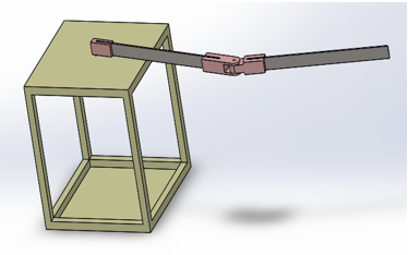
The controller was designed in Solidworks software for two -links flexible manipulator. Hence, the developed design was connected to the base of the two-link flexible manipulator using 2 degrees-of-freedom. Figure 1 shows the design for a double link robot manipulator. After the design step was completed, the design was evaluated to make sure that the moveable parts would be able to make a move. Next, after ensuring all the parts were in a good state, the design was exported to the Simscape toolbox in Simulink Matlab to proceed with the setup of the controller.
Figure 1. Double link robot manipulator
Simscape is a tool inside the Simulink that enables to design physical part of the system. It also compatible with a wide range of platforms. As a result, other design can easily be exported to the environments without the need to reconstruct the design. Simscape aids in the development of control systems as well as the testing of system-level performance. It uses block diagram approach hence make it easier to develop the system without using mathematical approach. The tools in Simscape is shown in Figure 2.
Figure 2. Simscape tools
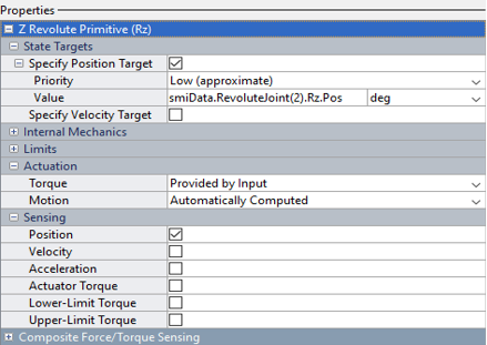
Then, after the design was successfully exported to the Simscape, the revolute joint needed to be set up. The setting of the revolute joint was to allow the link to follow the input signal given. The input for the revolute joint includes the actuation torque, which allows the signal to indicate the amount of torque applied to the joint primitive’s base and the follower frames. The output setting is the position of link to ensure the output follows the desired link position. The setting as shown in Figure 3 to compute the desired output.
Figure 3. Input Output Setting in Simscape
2.1 PID controller
Figure 4. Simulink block diagram for PID
It is known that PID is a conventional method and linear controller that has been tested in many flexible manipulators. For PID, the controller was set up using the Simulink controller. The components used were the signal builder, gain, PID controller and scope, as seen in Figure 4. The signal builder was used to provide an input trajectory signal for the system to follow. Gain was used to move the link based on the gain value. The value of the gain can be an equated value of the degree angle. PID controller was used to control the movement of both links. The output of the system will be given by the scope. Each of the joints consists of this component to ensure the links can move individually in the closed-loop system.
The PID controllers’ tuning makes things easier by selecting the appropriate tuning settings based on the study of the controlled process’s behavior. The tuning process was implemented using the auto-tuning method. The process of auto-tuning used the transfer function as illustrated by the Eq.1. The time response and transient behavior were tuned until the graph reference can track the slop.
$C(S)=K_P+\frac{K_1}{s}+s K_D$ (1)
where, $K_P$= Proportional gain, $K_1$= Integral gain and $K_D$= Derivative gain and often called as controller parameters.
2.2 Fuzzy logic controller
PID controller do not always work well and allow no flexibility of structure, a fuzzy logic controller could be tested and compared for this flexible manipulator system as a nonlinear controller. Block diagram for FLC is as same as PID controller except FLC using the Fuzzy toolbox. The toolbox helps to describe complicated system behaviors with basic logic rules, which you can subsequently be implemented in a fuzzy inference system. It can be used independently as a fuzzy inference engine. However, Simulink’s fuzzy inference blocks may be utilized to simulate the fuzzy systems as part of a larger model of the overall dynamic system. Figure 5 shows the block diagram for FLC that has been created in Simulink.
Figure 5. Simulink block diagram for FLC
After exporting the design from Solidwork, the signal builder was added to the system to provide the input of the PID controller design. Next, after the signal builder, Fuzzy logic is implemented as the controller for the system. In Fuzzy logic, a few things need to be modified, such as membership function and fuzzy sets.
Table 1 lists the fuzzy controller rule base, and 25 rule bases were developed as shown below, where NB is negative big, NS is negative small, Z is zero, PS is positive small, and PB is positive big.
Table 1. Rule notation for simulation
|
error Error dot |
NB |
NS |
Z |
PS |
PB |
|
NB |
NB |
NB |
NS |
NS |
Z |
|
NS |
NB |
NS |
NS |
NS |
Z |
|
Z |
NS |
NS |
Z |
PS |
PS |
|
PS |
NS |
Z |
PS |
PS |
PB |
|
PB |
Z |
PS |
PS |
PB |
PB |
After the simulation parts were completed, the hardware for each controller was developed. The joints for the robot manipulator were designed in Solidwork and were built using 3D printing. The hardware for each controller used Arduino to operate.
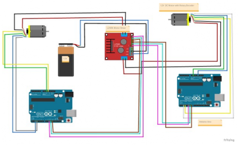
Figure 6 shows the circuit diagram on the connection of the DC motor, motor driver, power supply and Arduino Uno. The use of two Arduino Uno was due to the interruption pin limitation. Arduino Uno only has 2 interrupted pins. The dc motor has hall effect sensor attached to itself which when the rotating shaft produce two forms of square pulse, the square pulse uses to determine the direction of the dc motor. The interrupt pin is important to trigger which pulse to be executed. If pulse A was triggered, the direction of the DC motor will be on the positive side. While if Pulse B was triggered, the direction will be on the negative direction. Since two dc motor produces four square pulses, thus it is required to use two Arduino Uno.
Figure 6. Circuit Diagram
Figure 7. Design model
The design was developed in Solidwork before being implemented in a prototype. The joints for Link 1 and Link 2 were created using 3D printing. The design was set up as illustrated in Figure 7.
3.1 PID controller
The theory of PID was implemented in the system. The value of PID was used in the system. The value was extracted from the simulation data. However, the value will not be similar to the simulation due to the filter being coefficient in the simulation. Hence, the value needed to be used for the system is based on the try and error method until the system is stable enough to get the desired trajectory.
3.2 Fuzzy Logic Controller
The implementation of fuzzy logic to the prototype using Arduino was crucial to ensure that the Arduino software had the fuzzy library. Therefore, the Single Input Single Output was used in implementing the prototype. Table 2 lists the fuzzy controller rule base where NB is a negative big, NS is a negative small, Z is zero, PS is a positive small, and PB is a positive big.
Table 2. Rule notation for hardware
|
Input |
Output |
|
NB |
NB |
|
NS |
NS |
|
Z |
Z |
|
PS |
PS |
|
PB |
PB |
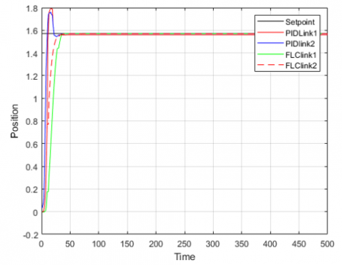
The simulation was conducted with a variety of controllers. PID and Fuzzy Controllers were developed, and simulations were presented in order to compare the controller’s performance as shown in Figure 8 and the respective performance is compared for Link1 and Link 2. The comparison will consist of overshoot, settling time, rise time and steady-state error. Figure 9 shows the performance using real hardware prototype.
Figure 8. Comparison for Simulation Performance of PID and FCL for link1 and link2
Figure 9. Comparison for Hardware Performance of PID and FCL for Link1 and Link2
4.1 Simulation
Table 3 indicates that FLC outperforms PID in terms of overshoot and steady-state error. However, in terms of the rise time and settling time, PID has a better performance. In Link 1 and Link 2 in PID, the comparison between the two links indicates an overshoot is higher in Link 1 because Link 1 needs to support the weight of both Link 1 and Link 2. Consequently, the rise time of Link 1 is higher than Link 2.
In Figure 9, the comparison was done by each flexible link 1 and link 2 attach to the dc motor. As for link 1 performance, it produced slightly better performance for PID as compared to FLC in terms of overshoot, rise time and settling time. Obviously as for link 2, the performance for both controllers showed high overshoot as there was another dc motor installed at the end of link 1. Again, PID link 2 was performed better than FLC link 2 in terms of overshoot, rise time and settling time. As shown in Figure 8 and Figure 9, overall result in the simulation and hardware performances show that PID outperformed FLC.
Table 3. Comparison of PID and FLC in simulation platform
|
Response parameter |
Link 1 |
Link 2 |
||
|
PID |
FLC |
PID |
FLC |
|
|
Overshoot (%) |
14.07 |
0 |
11.9817 |
0 |
|
Rise Time (s) |
0.1655 |
0.6863 |
0.1562 |
0.5361 |
|
Settling Time (s) |
0.8450 |
1.3503 |
0.8455 |
1.0799 |
|
Steady-state error |
0.011 |
-0.005 |
0.0018 |
-0.0005 |
4.2 Hardware
Table 4. Comparison of PID and FLC in hardware platform
|
Response parameter |
Link 1 |
Link 2 |
||
|
PID |
FLC |
PID |
FLC |
|
|
Overshoot (%) |
14.07 |
0 |
11.9817 |
0 |
|
Rise Time (s) |
0.1655 |
0.6863 |
0.1562 |
0.5361 |
|
Settling Time (s) |
0.8450 |
1.3503 |
0.8455 |
1.0799 |
|
Steady-state error |
0.011 |
-0.005 |
0.0018 |
-0.0005 |
Based on Table 4, the performance is compared in terms of the overshoot and steady-state error using the hardware prototype. Again, the PID outperforms the FLC. This is due to different rules applied to the system, which uses single input and single output in the hardware. As a result, PID has a better performance in terms of the rise and settling times.
Generally, the project’s effectiveness is based on its difficulty of application. The advantage of using Solidworks to design the double link flexible manipulator instead of designing directly in the Simulink is to allow the complex model to be designed efficiently in a shorter period. Hence, the results obtained are matched to the expected results. The results show that the implementation of the controller allows the system to follow the trajectory. However, due to the vibration that occurs, the system shows an overshoot at the trajectory lines. Fuzzy controllers are more stable, have less overshoot, and respond faster. Based on the results obtained from the hardware, the results from the simulation can become a reference to the hardware. The results are almost similar to each other’s systems. As a result, the proposed fuzzy logic-based controller can be implemented to eliminate overshoot and improve the steady-state error. As a result, in simulation, PID has better performance for both links in reducing settling time and rise time which is 0.5053s, 0.5308s for link1 and 0.2344s, 0.3799s for link 2. However, FLC outperforms PID controllers for both links in reducing overshoot and steady-state error, which are 14.07%, 0.005 for Link 1 and 11.9817%, 0.0005 for Link 2. On the other hand, FLC outperformed PID controller for both links in reducing rise time and steady-state error, namely 0.44s, 0 for Link1 and 0.1531s,1 for Link 2. As for FLC, although the result is not very good compare to PID but it responds well in the Flexible manipulators system, it requires excellent expertise in designing FLC. Currently the design for FLC is limited to single input and single output (SISO) system. As for future job recommendation, it requires Multi Input Multi Output (MIMO) system for better and accurate output performance for Fuzzy Logic Controller.
[1] Hussein, S., Saleh, M. (2014). A fuzzy logic controller for two-link functional manipulator. International Journal of Computer Networks and Communications, 6(6): 109-118. http://dx.doi.org/10.5121/ijcnc.2014.6608
[2] What is a Robotic Manipulator? - Robots Done Right. [Online]. Available: https://robotsdoneright.com/Articles/what-is-a-robotic- manipulator.html. Accessed on Feb. 04, 2022.
[3] Marzuki, Z.M., Mardiyah, N.A. (2017). Two-Link flexible manipulator control using sliding mode control based linear matrix inequality. International Conference on Recent Trends in Physics 2016 (ICRTP2016), 755: 13-14. http://dx.doi.org/10.1088/1757-899X/190/1/012008
[4] Milind, J.S., Arunkumar, G., Manjunath, T.C. (2018). PID control of a double link (2-link) flexible robotic manipulator (2-DOF) in the 3 DE space. In 2018 4th International Conference for Convergence in Technology (I2CT), pp. 1-7, http://dx.doi.org/10.1109/I2CT42659.2018.9058215
[5] Bhagwan, A., Soni, J.S., Kumar, A. (2015). A review on: PID controller. Ijrmee, 3: 17.
[6] Argo, B.D., Hendrawan, Y., Al Riza, D.F., Laksono, A.N.J. (2015). Optimization of PID controller parameters on flow rate control system using multiple effect evaporator particle swarm optimization. International Journal on Advanced Science, Engineering and Information Technology, 5(2): 62-68. http://dx.doi.org/10.18517/IJASEIT.5.2.491
[7] Akyüz, I.H., Bingül, Z., Kizir, S. (2012). Cascade fuzzy logic control of a single-link flexible-joint manipulator. Turkish Journal of Electrical Engineering and Computer Sciences, 20(5): 713-726. http://dx.doi.org/10.3906/elk- 1101-1056
[8] Kabir, U., Hamza, M.F., Haruna, A., Shehu, G.S. (2019). Performance analysis of PID, PD and fuzzy controllers for position control of 3- DOF robot manipulator. arXiv, 8(1): 8-25.
[9] Annisa, J., Darus, I.Z.M., Tokhi, M.O., Mohamaddan, S. (2018). Implementation of PID based controller tuned by evolutionary algorithm for double link flexible robotic manipulator. In 2018 International Conference on Computational Approach in Smart Systems Design and Applications (ICASSDA), pp. 5-9. http://dx.doi.org/10.1109/ICASSDA.2018.8477615
[10] Jamali, A., Darus, I.Z.M., Tokhi,M.O., Abidin, A.S.Z. (2018). Utilizing P-Type ILA in tuning hybrid PID controller for double link flexible robotic manipulator. In 2018 2nd Int. Conf. Smart Sensors Appl. ICSSA 2018, pp. 141-146. http://dx.doi.org/10.1109/ICSSA.2018.8535973
[11] Li, Y.N., Meng, D.S., Liu, H.D., Wang, X.Q., Bin, L. (2017). Modeling and control of a two-link flexible space manipulator using the wave-based method. 2017 29th Chinese Control and Decision Conference (CCDC), pp. 512-519. http://dx.doi.org/10.1109/CCDC.2017.7978148
[12] Vaishnav, S.R., Khan, Z.J. (2013). Design and simulation of PMSM drive for EPS applications using MATLAB. Circuits, Power and Computing Technologies (ICCPCT), In 2013 International Conference on Circuits, Power and Computing Technologies (ICCPCT), 8: 27-44. http://dx.doi.org/10.1109/ICCPCT.2013.6528942
[13] Kharidege, A., Ding, J.B., Zhang, Y.J. (2016). Performance study of PID and fuzzy controllers for position control of 6 DOF arm manipulator with various defuzzification strategies. In 2016 3rd International Conference on Mechanics and Mechatronics Research (ICMMR 2016), 77: 3-8. https://doi.org/10.1051/matecconf/20167701011
[14] Kala, H., Deepakraj, D., Gopalakrishnan, P., Vengadesan, P., Iyyar, M.K. (2014). Performance evaluation of fuzzy logic and PID controller for liquid level process. International Journal of Innovative Research in Electrical, Electronics, Instrumentation and Control Engineering, 2(3): 2321-5526.
[15] Mohammed, A.A., El-Nagar, A.M., Elsheikh, E.A., El-Bardini, M. (2022). Embedded adaptive 2-DOF PID controller for robot manipulator using a supervisory fuzzy logic system, Menoufia Journal of Electronic Engineering Research, 31(1): 55-62. https://dx.doi.org/10.21608/mjeer.2022.218822