Nacer Bouderres* | Djallel Kerdoun | Abdelhak Djellad | Sofiane Chiheb | Azzeddine Dekhane
© 2022 IIETA. This article is published by IIETA and is licensed under the CC BY 4.0 license (http://creativecommons.org/licenses/by/4.0/).
OPEN ACCESS
With the increasing integration of renewable energies into power grids, their control and power quality are becoming the main focus of many research efforts. In a grid-connected photovoltaic system, the control strategy is necessary to efficiently use the solar energy as well as to ensure high power quality. This paper presents a study on the robustness of a Fractional Order PI controller based on the Particle Swarm Optimization algorithm (PSO-FOPI) in a grid-connected PV system. The controller used was integrated into the inverter to apply voltage-oriented control (VOC). Fractional order controllers have an additional degree of freedom, so that a wider range of parameters is available to provide better control. Parameter optimization of the FOPI and classical PI controllers are performed using the PSO algorithm. The performance of the FOPI controller is compared with that of the classical PI controller. A complete study of the behavior of the grid connected PV system is tested using MATLAB/Simulink. The simulation results show the performance and efficiency of the PSO-FOPI controller compared to the classical PI controller in terms of rapidity, stability and precision, as well as the THD reduction of the current injected to the grid for any variation of solar irradiance.
PV, converter, MPPT, control, VOC, FOPI, PSO, THD
Nowadays, a great demand on electricity has been observed in the world due to the depletion of fossil fuels [1]. Which have a negative impact on the nature, such as air pollution, environmental destruction and non-renewable character [2]. To confront all these problems, the renewable energies present an alternative source which reduce environmental pollution, with free source and the possibility of its integration for providing electricity to rural, urban and remote areas [3]. Solar energy is one of these alternatives widely used in two modes: stand-alone and grid connected systems [4]. With the variation of photovoltaic voltage, a permanent adaptation of the load voltage with the panel one is required [5]. This adaptation can be achieved by inserting a DC/DC converter controlled by a MPPT mechanism. This system ensures the recuperation of maximum power generated by the PV panels. The mechanisms of MPPT are classified according to the algorithms used to adapt the DC voltage. In literature, the main algorithms used to control MPPT circuits are: Perturb and Observe (P&O), Incremental Conductance (IC), hill climbing and artificial intelligence (Fuzzy logic, neural networks, genetic algorithms, …) [6-8].
For grid connected systems, a DC/AC converter is used. Such converter requires a robust control to respect power quality conditions such as lower harmonic content [9]. A reversibility of this converter is required in some installations [10]. Many strategies have been proposed to control inverters of PV systems connected to power grids. They can be classified according to the parameter used in control loops: current or power [11, 12]. Indirect control technique of active and reactive power has been developed initially with the field orientation control (FOC) for induction motor: basically, the voltage vector is oriented with respect to the current one, known as voltage-oriented control (VOC) [13]. In other control, active and reactive power are calculated through input current and voltage measurements of PWM converters, with use of hysteresis comparators and switching table an instantaneous power control is done, which known as direct power control (DPC) [14]. DPC provide a good dynamic behavior due to the hysteresis controllers, on the other hand it doesn’t achieve a constant switching frequency and needs high sampling rate which are considered the principal disadvantages of DPC [15]. VOC and DPC are applied as bases of other controls using virtual flux for voltage estimation namely: Virtual Flux-based VOC (VFOC) and Virtual Flow-based DPC (VFDPC) methods [16, 17]. Ouchen et al. have proposed a direct power control strategy based on vector modulation (DPC-SVM) [18].
A PI/PID controller is added to track the loop reference. A stable and dynamic response are obtained with a fine-tuning of the controller parameters [19]. The quality and robustness of the control are improved by the high performance of controller [20]. The integration order in classical PID controller has been changed to fractional one to open a new generation of controllers known by Fractional Order PID (FOPID) [21]. A better specification response and flexibility of adjustment for the controlled system are remarked with the use of FOPID controller. Tunning FOPID parameters increases the robustness of controlled system and improve its response with regard to classical PID controlled one [22]. A detailed comparison between classical PID controllers and FOPID ones has been presented by Jain and Saravanakumar [23]. Kakkar et al. [9] have used the FOPID for manage the flux-oriented virtual control of PWM rectifier connected to power grid. Their simulation results have shown that fractional order is less sensitive to load and parameter variations, on the other hand injected power quality has been improved when comparing to the obtained using classical PID controller. A fractional filter has been proposed and added to FOPID controlling automatic voltage regulator (AVR) system to improve the response, the AVR system performance has been significantly improved due to the use of the fractional filter SCA-FOPIDFF controller [24]. A satisfactory response of the converter requires a tunning of controller parameters whatever its type: PID or FOPID. In literature, many algorithms have been proposed for tunning controller parameters such as Genetic Algorithm (GA) [25], Cuckoo Search Algorithm (CS) [26], Chaotic Ant Swarm Algorithm (CAS) [27], grey wolf optimization (GWO) [28], Water Cycle Algorithm (WCA) [9], sine cosine algorithm (SCA) [29], Gradient-Based Optimization (GBO) [21] and Particle Swarm Optimization (PSO) [30]. Among the cited algorithms, PSO has been chosen for the control of our converter. Inspired by dynamics of animals moving in compact groups, PSO build a solution to the proposed problem by simulating the swarm communications. In presence of continuous variables, PSO algorithm present an effective solution for optimization problem [30, 31].
Our present paper simulates a photovoltaic system connected to the grid through inverter controlled using current loops. The PWM is controlled by the voltage-oriented control (VOC) technique. A comparison between classical PI and FOPI controllers has been done. The novelty of our paper consists in the use of PSO algorithm to tune classical PI and FOPI parameters.
This paper is divided into five sections. The second section presents the main components of the system. The model of the inverter and proposed control with a FOPI controller is illustrated in section III. Our obtained results are shown and discussed in section IV. Finally, a conclusion shows the main remarks and perspectives.
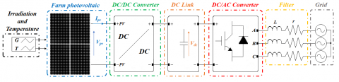
The Figure 1 illustrates the totality of our complete system and all of the used converters until reaching the power grid: A PV composed of several strings are supplying a DC/DC converter. This later adapting the output voltage to the one required by DC link. The energy at the DC link is converted to AC form by an inverter (DC/AC converter). The energy injected to the power grid pass through a filter. For further details, each part implemented into this system will be clearly presented in the next subsections.
Figure 1. Structure of the complete system
2.1 PV model
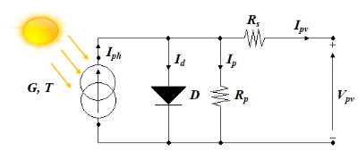
The PV panels contains a series of cells, each one can be modelled by a circuit composed of current source, a diode and some resistances [32] as shown in Figure 2.
Figure 2. PV cell model
The cell generated current is given by the following equation [32]:
$\begin{aligned} \mathrm{I}_{\mathrm{pv}}=\mathrm{I}_{\mathrm{ph}}-\mathrm{I}_{\mathrm{s}} \times\left[\exp \left(\frac{\mathrm{q} \times\left(\mathrm{V}+\mathrm{R}_{\mathrm{s}} \times \mathrm{I}\right)}{\mathrm{A} \times \mathrm{K} \times \mathrm{T}_{\mathrm{c}}}\right)-1\right]- &\left(\frac{\mathrm{V}_{\mathrm{pv}+\mathrm{R}_{\mathrm{s}} \times \mathrm{I}_{\mathrm{pv}}}}{\mathrm{R}_{\mathrm{sh}}}\right) \end{aligned}$ (1)
With:
$\mathrm{I}_{\mathrm{pv}}$ and $\mathrm{V}_{\mathrm{pv}}$ are the cell output current and voltage;
$I_{p h}:$ The photon current;
$\mathrm{I}_{\mathrm{S}}:$ The saturation current of the diode;
$R_s$ and $R_{s h}$ are series and parallel resistances respectively;
q: The electron charge (1,6 .10-19 C);
A: The ideality factor of the P-N junction;
K: Boltzmann constant ($1,380649 \times 10^{-23} J \cdot K^{-1}$);
$T_c:$ Absolute cell temperature in Kelvin (K).
Table 1. PV panel parameters
|
Parameter |
Value |
|
$\mathrm{P}_{\mathrm{mp}}$ |
315.072 W |
|
$V_{\mathrm{mp}}$ |
54.7 V |
|
$\mathrm{I}_{\mathrm{mp}}$ |
5.76 A |
|
$V_{o c}$ |
64.6 V |
|
$\mathrm{I}_{\mathrm{SC}}$ |
6.28 A |
|
$N_S$ |
96 cells |
There are several types of solar panels with different parameters. In our simulation, we have used the parameters of the model (SPR-315E WHT-D). The PV array is composed of 12 parallel strings, each string contains 4 panels connected in series, the total generates 15 kw. The Table 1 presents the considered PV panel parameters.
2.2 DC/DC converter model
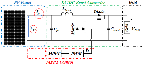
The photovoltaic systems are equipped of DC/DC converters which are destinated to adjust panel voltage to a constant value fixed in DC link. For the case of grid connected photovoltaic system Boost topology is used [6]. The Boost converter is characterized by its simple structure, consisting of an inductor, a switch, a diode and a capacitor as shown in Figure 3. The chosen parameters are illustrated in Table 2.
Table 2. Functioning Boost parameters
|
Parameter |
Value |
|
$C_{p v}$ |
50 mF |
|
$\mathrm{L}_{\text {Boost }}$ |
4 mH |
|
$\mathrm{C}_{\text {Boost }}$ |
100 mF |
|
f |
15 kHz |
The output voltage of Boost converter depends to the used duty cycle α (between 0 and 1, with $\alpha \neq 1)$) as presented in the next Eq. (2) [33]:
$\mathrm{V}_{\text {boost }}(1-\alpha)=V_{\mathrm{pv}} \Rightarrow \mathrm{V}_{\text {boost }}=\frac{\mathrm{V}_{\mathrm{pv}}}{(1-\alpha)}, \alpha \neq 1$ (2)
With $V_{\mathrm{pv}}$: Input voltage, $V_{\text {boost }}$: Output voltage converter.
The choose of this duty cycle under the effect of irradiance variation is controlled by incremental conductance algorithm (IC) in order to track the maximum power (MPPT) generated by PV array [6].
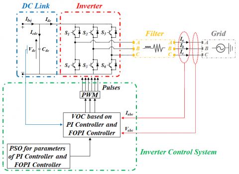
A DC/AC converter (inverter) is used to adapt PV energy to the power grid one. To ensure this adaptation, an adequate control system is used which takes into account DC side parameters and AC side ones as shown in Figure 4.
A filter is placed between the inverter and the grid in order to eliminate harmonic content of generated signal. The parameters of the power grid and this filter elements are illustrated in Table 3.
Table 3. Grid and filter parameters
|
Parameter |
Value |
|
$\mathrm{L}_{\mathrm{f}}$ |
0.003 H |
|
$\mathrm{R}_{\mathrm{f}}$ |
0.01 ohm |
|
$\mathrm{U}_{\mathrm{a}}$ |
380 V |
|
$f_g$ |
50Hz |
Several configurations and control systems exist in DC/AC converters, but basically two essential parts distingue each converter to the other: inverter topology and control system type.
3.1 Inverter
The inverter is a power electronic converter composed of controlled interrupters. The commonly used configuration for PV systems is PWM inverter (already shown in Figure 4).
The following Eq. (3) gives the inverter output voltages [13]:
$\left[\begin{array}{c}\mathrm{V}_{\mathrm{an}} \\ \mathrm{V}_{\mathrm{bn}} \\ \mathrm{V}_{\mathrm{cn}}\end{array}\right]=\frac{\mathrm{v}_{\mathrm{dc}}}{3}\left[\begin{array}{ccc}2 & -1 & -1 \\ -1 & 2 & -1 \\ -1 & -1 & 2\end{array}\right] \cdot\left[\begin{array}{l}\mathrm{S}_{\mathrm{a}} \\ \mathrm{S}_{\mathrm{b}} \\ \mathrm{S}_{\mathrm{c}}\end{array}\right]$ (3)
where: $\mathrm{S}_{\mathrm{a}}$, $\mathrm{S}_{\mathrm{b}}$, $\mathrm{S}_{\mathrm{c}}$ are commutation functions.
The pulses injection is decided and injected by a control system.
3.2 Inverter control system
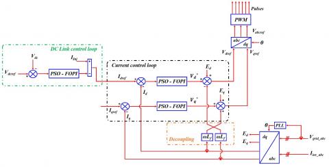
The grid-connected PV system uses the inverter to control the injected active and reactive power [34, 35]. The control strategy implemented in the inverter is responsible for achieving the unit power factor of the grid-connected PV system. To solve power quality problems, voltage-oriented control (VOC) is proposed to indirectly provide active and reactive power control [36].
The latter consists of two control loops. One control loop is designed to regulate the DC bus voltage of the system to balance the power flow and ensure stability during dynamics, while the secondary loop controls the currents of the two d-q axes to be injected into the grid by the PWM technique [13]. In addition, the PWM block is used to generate the signals for each switch in the inverter [37]. Then, a phase-locked loop (PLL) device is employed to generate a reference current synchronized with the current control loop [38].
Figure 5 shows the control method applied to the grid connected PV system. Through the Park transformation (abc/dq), the diagram shows that the reference active component on the direct axis ($\mathrm{I}_{\mathrm{dref}}$) is obtained from the DC side voltage controller, at the same time the reference reactive component on the quadrature axis ($\left(\mathrm{I}_{\text {qref }}\right)$) is determined by the reactive power controller, as demonstrated in Eqns. (4) and (5).
$\mathrm{I}_{\mathrm{dref}}=\left[\mathrm{I}_{\mathrm{inj}}-\left(\mathrm{K}_{\mathrm{pdc}}+\frac{\mathrm{K}_{\mathrm{idc}}}{\mathrm{s}^{\lambda \mathrm{dc}}}\right)\left(\mathrm{V}_{\mathrm{dcref}}-\mathrm{V}_{\mathrm{dc}}\right)\right]$ (4)
$\mathrm{I}_{\text {qref }}=0$ (5)
where: $\mathrm{I}_{\mathrm{inj}}$ the injected current; $V_{\text {dcref }}$ and $\mathrm{V}_{\mathrm{dc}}$ the reference and measured DC bus voltages.
The active and reactive reference component is maintained at a well determined value by using the FOPI controller.
Reference voltages in the dq reference axis ($V_{\text {dref }}$, $V_{\text {qref }}$) which are injected into the inverter by the PWM technique, can be achieved by using the FOPI controllers and the decoupling block, as given in the following Eqns. (6), (7), (8) and (9):
$\mathrm{V}_{\mathrm{d}}^*=\left(\mathrm{K}_{\mathrm{p}}+\frac{\mathrm{K}_{\mathrm{i}}}{\mathrm{s}^\lambda}\right)\left(\mathrm{I}_{\mathrm{dref}}-\mathrm{I}_{\mathrm{d}}\right)$ (6)
$\mathrm{V}_{\mathrm{q}}^*=\left(\mathrm{K}_{\mathrm{p}}+\frac{\mathrm{K}_{\mathrm{i}}}{\mathrm{s}^\lambda}\right)\left(\mathrm{I}_{\mathrm{qref}}-\mathrm{I}_{\mathrm{q}}\right)$ (7)
where: $V^*{ }_{\mathrm{d}}$, $\mathrm{V}^* \mathrm{q}$ the voltages that are calculated by the FOPI controller; $\mathrm{I}_{\mathrm{d}}$, $\mathrm{I}_{\mathrm{q}}$ the currents measured on the direct and quadrature axes respectively.
$V_{\text {dref }}=E_d+V_d^*-\omega L_f I_q$ (8)
$V_{\text {qref }}=E_q+V_q^*+\omega L_f I_d$ (9)
where: $\mathrm{E}_{\mathrm{d}}$, $E_q$ the voltages of the common connection points to the grid; $\mathrm{L}_{\mathrm{f}}$ is the coupling inductance of the filter device.
Figure 5. Detailed diagram of control
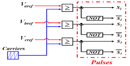
Lastly, by using the inverse Park transformation (dq/abc), we can obtain the values of the reference voltages ($V_{a b c r e f}$) which are used to generate the switching signals (S1, S2, ..., S6) based on a pulse width modulation (PWM) control (Figure 6).
Figure 6. PWM control strategy
3.2.1 Fractional order PID controller
In recent years, researchers have been interested in a new design of the PID controller to be applied in many domains, especially control theories compared to classical PID controllers because of their advantages, which are to increase the performance of non-linear, dynamic systems and to be less sensitive to changes in system parameters [9, 39].
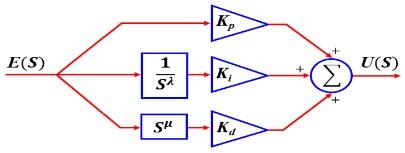
This control device is named fractional order PID (or FOP $I^\lambda D^\mu$) and has been proposed by Podlunby since the 1990s [40]. In addition to the control parameters $K_p$, $K_i$ and $K_d$ of a classical PID controller, there are $\lambda$ and $\mu$, the fractional components of the integral and derivative parts respectively.
Figure 7 illustrates the block diagram of the fractional order PID controller.
Figure 7. Structure of FOPID controller
The mathematical expression of the fractional order PID controller can be presented in the following differential equation [40]:
$u(t)=\left(K_p+K_i D_t^{-\lambda}(t)+K_d D_t^{-\mu}(t)\right) e(t)$ (10)
where: $u(t)$ Controller output; $e(t)$ Error.
By application of Laplace transform on Eq. (10). With zero initial conditions, the transfer function of this controller is defined by Eq. (11) [40]:
$\mathrm{G}(\mathrm{S})=\frac{\mathrm{U}(\mathrm{S})}{\mathrm{E}(\mathrm{S})}=\mathrm{K}_{\mathrm{p}}+\mathrm{K}_{\mathrm{i}} \mathrm{S}^{-\lambda}+\mathrm{K}_{\mathrm{d}} \mathrm{S}^\mu,(\lambda, \mu>0)$ (11)
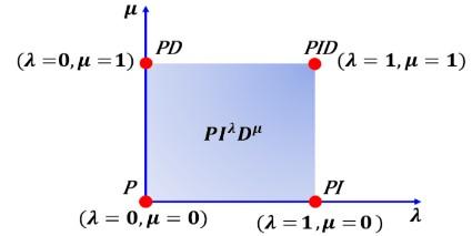
$K_p$, $K_i$ and $K_d$ are proportional, integral and derivative gain constants respectively; $\lambda$ and $\mu$ are the fractional order of the integral and derivative term. For a classical PID controller, the values ($\lambda$ and $\mu$) are equal to 1. As indicated in Figure 8, which shows the classical PID and FOPID control domains.
Figure 8. Domains of FOPID and classical PID controllers
The design of the FOPID controller requires five parameters, whereas the classical PID controller only needs to optimize three parameters. This extension adds more flexibility in realizing the dynamics of the control system [34].
The adjustment of controller parameters is an essential element in a control system. Due to the complexity of the system under study, direct synthesis of the controller parameters is not simple. Determining the parameters of the controller is time demanding and may not be the best. Optimisation techniques are therefore used as they require less time and give the best values of the controller parameters [9].
Some optimisation techniques have been used to adjust the parameters of fractional order controllers, such as the Artificial Bee Colony (ABC) algorithm [41], the Bat Optimisation Algorithm (BA) [42], the Water Cycle Algorithm (WCA) [9], the Grey Wolf Optimisation (GWO) [43] and the Ant Colony Optimisation (ACO) [44]. The particle swarm optimisation (PSO) method is inspired by biology and is one of the most widely implemented methods for the determination and optimisation of controller parameters.
In the present study, a particle swarm optimisation (PSO) algorithm is applied to optimise the parameters of the classical PI and FOPI controllers.
3.2.2 Particle Swarm Optimization (PSO) algorithm
Particle swarm optimization is an evolutionary algorithm that uses a population of candidate solutions to develop an optimal solution to the problem [45]. Inspired by the observation of the social behavior of the movement of certain swarming animals such as bees, ants, fish schools and flocks of birds [46, 47].
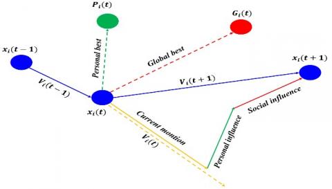
This basic concept of the algorithm consists in using a swarm containing (n) particles, these particles representing potential solutions to the problem to be solved, which moves and searches for the global optimum ($G_i(t)$) in the multidimensional search space. Indeed, each particle has a memory of its best visited solution ( $P_i(t)$) and the ability to communicate with its adjacent particles [48]. Thus, particles have a strong ability to explore new areas in search of optimal candidate solutions [49]. The displacement of particles is not random, they have a purpose to achieve. All particles within the swarm are able to move towards the desired objective. In order to reach a new and better position, each particle uses its best experience and that of the others [50]. To maintain the cohesion of the swarm and allow it to implement a complex and adaptive collective behavior, the movement of all particles follows simple rules: they are attracted to the average position of the group, follow the same path as their neighbours, separation to avoid collisions and the particles keep a certain distance between them [51].
Figure 9 illustrates the movement strategy of a particle, each particle movement in the swarm is an updated velocity and position vector which are calculated from Eqns. (4) and (5) respectively [45].
Figure 9. Movement of the PSO swarm
$V_i(k+1)=w * V_i(k)+C_1 * r_1\left[P_i(k)-x_i(k)\right]+$$C_2 * r_2\left[G_i(k)-x_i(k)\right]$ (12)
$x_i(k+1)=x_i(k)+V_i(k+1)$ (13)
where: w adaptive inertia factor; $V_i(k)$ velocity of the particles at iteration k; $x_i(k)$ position of the particles in the search space at iteration k; $C_1$ and $C_2$ are positive constants, named respectively the cognitive and social factor, which control the individual and collective behavior of each particle; $r_1$ and $r_2$ random numbers uniformly distributed in the interval [0, 1].
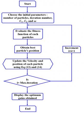
The model of the PSO algorithm can be presented in the flowchart below (Figure 10).
Figure 10. Flowchart of PSO algorithm
3.2.3 Tuning parameters
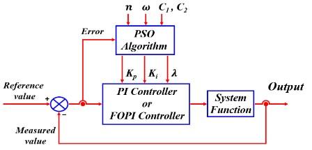
Figure 11. Block diagram for PSO-PI or PSO-FOPI controllers
As described above, the particle swarm optimisation (PSO) algorithm adjusts the parameters of the classical PI and FOPI controllers.
The block diagram of the optimisation process for both the PSO-PI or PSO-FOPI controllers are presented in Figure 11.
Within optimisation techniques, there are several criteria of suitability for evaluating system performance, such as integral absolute error (IAE), integral square error (ISE), and integral time-weighted absolute error (ITAE). The latter include: overshoot, rise time, settling time and steady state error [52]. In the context, the fitness function Integral Time Absolute Error (ITAE), which is used as a performance criterion for the output response of the system. The ITAE is defined as follows:
$I T A E=\int_0^{t_{s i m}} t|e(t)| d t$ (14)
To find the values for both classical PI and FOPI controllers, we use: $w=0.7$; $C_1=C_2$ and n=50. The optimised parameter values are shown in Table 4 with k=300 iterations.
Table 4. Tuning parameters for classical PI and FOPI controllers
|
|
PI Classical |
FOPI Classical |
|||
|
$K_i$ |
$K_p$ |
$K_i$ |
$K_p$ |
$\lambda$ |
|
|
DC-Link voltage |
1.4008 |
95.2529 |
4.2680 |
16.6173 |
0.9764 |
|
d-axis current |
2.3541 |
45.0714 |
29.1395 |
84.8670 |
0.8929 |
|
q-axis current |
2.3541 |
45.0714 |
29.1395 |
84.8670 |
0.8929 |
Our proposed model of the grid-connected PV system, shown in Figure 1, is implemented in Matlab/Simulink to evaluate the effectiveness of the proposed VOC method using PSO-PI and PSO-FOPI.
The study is based on two types of tests, one with classsical PI controllers and the other with fractional order PI controllers. The choice of the optimization method by the PSO algorithm allows to determine the parameters ($\mathrm{K}_{\mathrm{p}}, \mathrm{K}_{\mathrm{i}}, \lambda$) of both controllers. The parameters of the system and controllers are shown in Tables 1, 2, 3 and 4.
The simulation was carried out for varying irradiance conditions, with a fixed ambient temperature (25℃), to test the performance of the controllers used.
4.1 PV side results
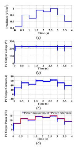
Figure 12. PV system (a) Irradaince profil (b) Output voltage (c) Output current (d) Output power
The applied irradiance has been variated seven times with a range between 0.45 and 1 kW/m², the time step was 0.5 seconds. The results illustrated in Figure 12 are limited to the ones concerns the PV array: (a) presents the irradiance profile applied to the PV array, (b) the voltage obtained at the input of the MPPT controller. In (c) we illustrate the current generated by the PV array, while the output power of the PV array is shown in figure (d) with a comparison to the power reference suggested by MPPT control using the IC method, and a good accordance is noted.
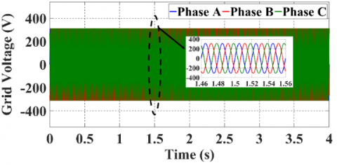
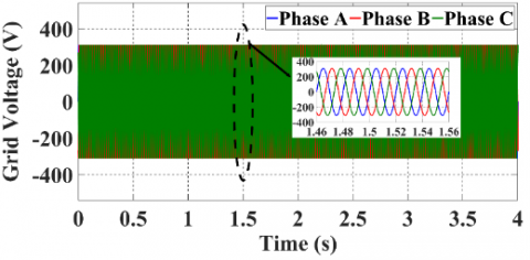
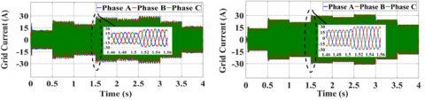
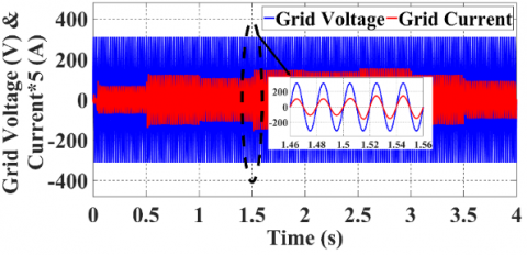
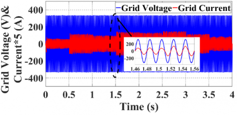
For the system connected to power grid, the three phase voltages, injected currents, single phase current and voltage are illustrated in Figure 13. Figure 13 (a-c) present the obtained results with classical PI controller, while the results obtained with fractional order PI controller are shown in Figures 13 (a’-c’). To indicate the impact of irradiance variation on the current and voltage, we focus on the time range [1.46 s-1.56 s] where the irradiance has increased from 700 to 950 W/m2. We observe that only the current magnitude has been affected by the irradiance variation (Figures 13 b and b’), while the voltage magnitude remains constant (Figures 13 a and a’), and this for both controllers.
When comparing between Figures 13 (b) and (b’), it is obvious that current waveform has been improved with the use of FOPI controller. Even with irradiance variation, the PLL control system kept the current in phase with the voltage, as shown in Figures 13 (c) and (c').
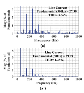
To illustrate the impact of the controller on the power quality, a spectrum analysis of the obtained current with Standard Test Conditions (STC) is done, and the harmonic spectrum is presented in Figures 14 (a) and (a’). It should be noted that THD obtained with classical PI controller is 3.56% while a THD of 1.35% has been obtained with FOPI controller, which proves the efficiency of FOPI controller compared to the classical PI.
|
VOC with PI Classical |
VOC with Fractional order PI |
|
(a) |
(a') |
|
(b) |
(b') |
|
(c) |
(c') |
Figure 13. Grid connection of PV system with PSO-PI classical and PSO-FOPI: (a, a') Three-phase voltages; (b, b') Three-phase Currents; (c, c') Single phase voltage and current
Figure 14. Current THD analysis (a) with classical PI (a’) Fractional order PI (STC conditions)
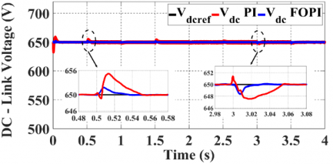
In order to show the high performance in terms of response time and overshoot, Figure 15 shows the comparison of the voltage at the DC bus for both the classical PSO-PI and PSO-FOPI controllers.
The parameters of the classical PI and FOPI controllers are obtained by the PSO algorithm as shown in Table 4.
Figure 15. Voltage DC Link of PI and FOPI
It can be observed that the settling time of the FOPI controller is less than that of the classical PI controller, so the FOPI controller has improved the stability of the system. The overshoot recorded is 656 V with the classical PSO-PI controller, while with the PSO-FOPI controller the overshoot is 652 V. The response time is 0.024 s with PSO-FOPI and 0.046 s with the PSO-PI controller. From these parameters, the PSO-FOPI performs very well in terms of rapidity and stability.
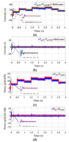
Figure 16 shows a comparison between the robustness of the two controllers: classical PI and FOPI. The current reference value $\mathrm{I}_{\mathrm{dref}}$ controls the active power, while the reactive power is controlled by the reference current $\mathrm{I}_{\mathrm{qref}}=0$ to guarantee the unity power factor.
We notice in the interval [0 s-0.2 s] that the transient responses of the FOPI controller of the active and reactive powers are characterised by a very small overshoot compared to the conventional PI controller, whereas the steady state error is nearly zero as shown in Figure 16 (c) and (d).
According to the results obtained, the VOC strategy with FOPI is better than VOC with classical PI in terms of rapidity, stability of the system and precision.
Comparative analysis
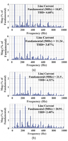
With a variable irradiance, harmonic analysis has been effected to the injected grid current, where the THD and fundamental magnitude obtained for each irradiance value are illustrated in Table 5.
Figure 16. Control currents and powers with classical PI and FOPI (a,b) current $\mathrm{I}_{\mathrm{d}}$, $\mathrm{I}_{\mathrm{q}}$ (c,d) active and reactive powers
Table 5. THDs of line current Iabc during variable irradiance
|
Irradiance (W/m2) |
Line current $\mathbf{I}_{a b c}$ |
|||
|
PI Classical |
Fractional order PI |
|||
|
THD% |
FD |
THD% |
FD |
|
|
450 |
4.60 |
10.87 |
3.07 |
11.24 |
|
800 |
4.32 |
21.50 |
2.40 |
20.91 |
|
1000 |
3.56 |
27.39 |
1.35 |
29.09 |
It is obvious that when the irradiance increases, the current harmonic content decreases. It should be noted that for both controllers, and what ever the irradiance the harmonic pollution still below 5% as recommended by the IEEE-519 standard [1, 53].
This pollution is quantified by a THD of 4.60%, 4.32% and 3.56% for applied irradiance of 450 W/m2, 800 W / m2 and 1000 W/m2 and these values are obtained with classical PI controller. With using FOPI controller, the current quality has been improved, and this is by reducing THD to 3.07%, 2.40% and 1.35% when applying same irradiance values respectively. The most powerful functioning of our FOPI controller is recorded with 1000 W/m2 irradiance (Figure 14), and this by reducing 62.07% of the THD irradiance. For more details, the frequency spectrum of each current with 450 and 800 W/m² is presented in Figure 17.
Figure 17. Harmonic spectrum analysis of current with classical PI and FOPI (a) Irradiance 450, (b) Irradiance 800
From the simulation results, the proposed FOPI controller provides an improved and satisfactory transient behaviour compared to the classical PI controller. Therefore, due to the flexibility of the FOPI controller which is able to achieve the desired response with reduced overshoot and settling time.
In this paper, a decoupled control of PV system connected to the grid using PSO-FOPI controller has been presented. The studied system has been developed and simulated using MATLAB/Simulink. The inverter connecting the PV system to the grid has been controlled by two different controllers namely classical PI and FOPI. The PSO algorithm has been used to optimize both controller parameters. A comparative analysis has been done between the obtained results and this on different levels: DC link and AC grid. In the DC link a comparison of settling time and overshoot, where the FOPI has reduced around 50% of settling time and the overshoot recorded is below 1% of the reference DC link. The overshoots reduced have participated in the disturbances recorded in the power when changing the applied irradiance. For AC grid side, the inverter with both controllers have generated a stable AC voltage which is not disturbed by irradiance variation. While the remarkable difference between controllers has been recorded with the injected current, especially with its waveform: the harmonic spectrum analysis of the grid currents has proved that the PSO-FOPI controller has reduced the THD with respect to the IEEE-519 standard recommendations, and this whatever the applied irradiance. So the PSO-FOPI strategy have optimized the grid connected PV system in question of the rapidity, stability and precision with power quality improvement. Results verify the better performance of PSO-FOPI in terms of settling time, rise time, peak overshoot, and total harmonic distortion (THD) of the grid current. PSO-FOPI demonstrates greater robustness compared to PSO-PI. The simulation validates the results of the PSO-FOPI controller over the PSO-PI in terms of control effect and robustness.
|
PV |
Photovoltaic |
|
STC |
Standard Test Conditions |
|
THD |
Total Harmonic Distortion |
|
FD |
Fundamental frequency |
|
PWM |
Pulse width modulation |
|
PSO |
Particle warm optimization |
|
MPPT |
Maximum power point tracking |
|
$V_{m p}$ |
Maximum power voltage |
|
$\mathrm{I}_{\mathrm{mp}}$ |
Maximum power current |
|
$\mathrm{V}_{\mathrm{OC}}$ |
Open circuit voltage |
|
$I_{S C}$ |
Short circuit current |
|
$\mathrm{n}_{\mathrm{s}}$ |
Number of cells |
|
$C_{p v}$ |
Input capacitor |
|
$\mathrm{L}_{\text {boost }}$ |
Converter inductor |
|
$\mathrm{C}_{\text {boost }}$ |
Converter capacitor |
|
$\mathrm{L}_{\mathrm{f}}$ |
Filter inductor |
|
$\mathrm{R}_{\mathrm{f}}$ |
Filter resistor |
|
$\mathrm{U}_{\mathrm{a}}$ |
Grid voltage |
|
$\mathrm{f}_{\mathrm{g}}$ |
Grid frequency |
[1] Djellad, A., Belakehal, S., Chenni, R. and Dekhane, A. (2021). Reliability improvement in serial multicellular converters based on STATCOM control. Journal Européen des Systèmes Automatisés, 54(4): 519-528. https://doi.org/10.18280/jesa.540401
[2] Sharma, S., Sood, Y.R., Sharma, N.K., Bajaj, M., Zawbaa, H.M., Turky, R.A., Kamel, S. (2022). Modeling and sensitivity analysis of grid-connected hybrid green microgrid system. Ain Shams Engineering Journal, 13(4): 101679. https://doi.org/10.1016/j.asej.2021.101679
[3] Wadawa, B., Errami, Y., Obbadi, A., Sahnoun, S. (2021). Robustification of the H∞ controller combined with fuzzy logic and PI&PID-Fd for hybrid control of wind energy conversion system connected to the power grid based on DFIG. Energy Reports, 7: 7539-7571. https://doi.org/10.1016/j.egyr.2021.10.120
[4] Pandey, A., Pandey, P., Tumuluru, J.S. (2022). Solar energy production in india and commonly used technologies—an overview. Energies, 15(2): 500. https://doi.org/10.3390/en15020500
[5] Kitmo, Djidimbélé, R., Kidmo, D.K., Tchaya, G.B., Djongyang, N. (2021). Optimization of the power flow of photovoltaic generators in electrical networks by MPPT algorithm and parallel active filters. Energy Reports, Technologies and Materials for Renewable Energy, Environment and Sustainability, 7: 491-505. https://doi.org/10.1016/j.egyr.2021.07.103
[6] Bhattacharyya, S., Kumar P, D.S., Samanta, S., Mishra, S. (2021). Steady output and fast tracking MPPT (SOFT-MPPT) for P&O and Inc algorithms. IEEE Transactions on Sustainable Energy, 12(1): 293-302. https://doi.org/10.1109/TSTE.2020.2991768
[7] Jately, V., Azzopardi, B., Joshi, J., Venkateswaran V.B., Sharma, A., Arora, S. (2021). Experimental analysis of hill-climbing MPPT algorithms under low irradiance levels. Renewable and Sustainable Energy Reviews, 150: 111467. https://doi.org/10.1016/j.rser.2021.111467
[8] Mao, M., Cui, L., Zhang, Q., Guo, K., Zhou, L., Huang, H. (2020). Classification and summarization of solar photovoltaic MPPT techniques: A review based on traditional and intelligent control strategies. Energy Reports 6: 1312-1327. https://doi.org/10.1016/j.egyr.2020.05.013
[9] Kakkar, S., Maity, T., Ahuja, R.K., Walde, P., Saket, R.K., Khan, B., Padmanaban, S. (2021). Design and control of grid-connected PWM rectifiers by optimizing fractional order PI controller using water cycle algorithm. IEEE Access, 9: 125941-125954. https://doi.org/10.1109/ACCESS.2021.3110431
[10] Sabzian-Molaee, Z., Rokrok, E., Doostizadeh, M. (2022). An optimal planning model for AC-DC distribution systems considering the converter lifetime. International Journal of Electrical Power & Energy Systems, 138: 107911. https://doi.org/10.1016/j.ijepes.2021.107911
[11] Chowdhury, V.R. (2021). Internal model based grid voltage estimation and control of a three-phase grid connected inverter for PV application. IEEE Transactions on Energy Conversion, 36(4): 3568-3577. https://doi.org/10.1109/TEC.2021.3079908
[12] Zhang, Y., Liu, J., Yang, H., Gao, J. (2018). Direct power control of pulsewidth modulated rectifiers without DC voltage oscillations under unbalanced grid conditions. IEEE Transactions on Industrial Electronics, 65(10): 7900-7910. https://doi.org/10.1109/TIE.2018.2807421
[13] Kadri, R., Gaubert, J.P., Champenois, G. (2011). An improved maximum power point tracking for photovoltaic grid-connected inverter based on voltage-oriented control. IEEE Transactions on Industrial Electronics, 58(1): 66-75. https://doi.org/10.1109/TIE.2010.2044733
[14] Chaoui, A., Gaubert, J.P., Krim, F. (2010). Power quality improvement using DPC controlled three-phase shunt active filter. Electric Power Systems Research, 80(6): 657-666. https://doi.org/10.1016/j.epsr.2009.10.020
[15] Yang, G., Fu, C., Yi, H., Chai, C., Huang, B., Hao, S., Chen, Z. (2018). Direct power control of three-level NPC grid-connected system combined with fault-tolerant technology. Microelectronics Reliability, 88-90: 1057-1062. https://doi.org/10.1016/j.microrel.2018.07.140
[16] Chettibi, N., Mellit, A. (2018). Intelligent control strategy for a grid connected PV/SOFC/BESS energy generation system. Energy, 147: 239-262. https://doi.org/10.1016/j.energy.2018.01.030
[17] Xiao, X., Zhang, Y., Song, X., Yildirim, T., Zhang, F. (2018). Virtual flux direct power control for PWM rectifiers based on an adaptive sliding mode observer. IEEE Transactions on Industry Applications, 54(5): 5196-5205. https://doi.org/10.1109/TIA.2018.2832122
[18] Ouchen, S., Steinhart, H., Benbouzid, M., Blaabjerg, F. (2020). Robust DPC-SVM control strategy for shunt active power filter based on H∞ regulators. International Journal of Electrical Power & Energy Systems, 117: 105699. https://doi.org/10.1016/j.ijepes.2019.105699
[19] Jain, A., Saravanakumar, R. (2020). Comparative analysis of fractional order PI and integer order PI based controller for hybrid standalone wind energy conversion system. Environmental Progress & Sustainable Energy 39(2): e13293. https://doi.org/10.1002/ep.13293
[20] Lorenzini, G., Kamarposhti, M.A., Solyman, A.A.A. (2021). Optimization of PID controller parameters for automatic generation control in two-area heating system using firefly algorithm. International Journal of Safety and Security Engineering, 11(3): 213-222. https://doi.org/10.18280/ijsse.110301
[21] Altbawi, S.M.A., Mokhtar, A.S.B., Jumani, T.A., Khan, I., Hamadneh, N.N., Khan, A. (2021). Optimal design of Fractional order PID controller based Automatic voltage regulator system using gradient-based optimization algorithm. Journal of King Saud University-Engineering Sciences. https://doi.org/10.1016/j.jksues.2021.07.009
[22] Erol, H. (2021). Stability analysis of pitch angle control of large wind turbines with fractional order PID controller. Sustainable Energy, Grids and Networks, 26: 100430. https://doi.org/10.1016/j.segan.2021.100430
[23] Jain, A., Saravanakumar, R. (2020). Comparative analysis of fractional order PI and integer order PI based controller for hybrid standalone wind energy conversion system. Environmental Progress & Sustainable Energy, 39(2): e13293. https://doi.org/10.1002/ep.13293
[24] Ayas, M.S., Sahin, E. (2021). FOPID controller with fractional filter for an automatic voltage regulator. Computers & Electrical Engineering, 90: 106895. https://doi.org/10.1016/j.compeleceng.2020.106895
[25] Altintas, G., Aydin, Y. (2017). Optimization of fractional and integer order PID parameters using big bang big crunch and genetic algorithms for a maglev system. IFAC-PapersOnLine, 20th IFAC World Congress, 50(1): 4881-4886. https://doi.org/10.1016/j.ifacol.2017.08.978
[26] Karahan, O. (2021). Design of optimal fractional order fuzzy PID controller based on cuckoo search algorithm for core power control in molten salt reactors. Progress in Nuclear Energy, 139: 103868. https://doi.org/10.1016/j.pnucene.2021.103868
[27] Tang, Y., Cui, M., Hua, C., Li, L., Yang, Y. (2012). Optimum design of fractional order PIλDμ controller for AVR system using chaotic ant swarm. Expert Systems with Applications, 39(8): 6887-6896. https://doi.org/10.1016/j.eswa.2012.01.007
[28] Fu, W., Wang, K., Li, C., Tan, J. (2019). Multi-step short-term wind speed forecasting approach based on multi-scale dominant ingredient chaotic analysis, improved hybrid GWO-SCA optimization and ELM. Energy Conversion and Management, 187: 356-377. https://doi.org/10.1016/j.enconman.2019.02.086
[29] Suid, M.H., Ahmad, M.A. (2021). Optimal tuning of sigmoid PID controller using nonlinear sine cosine algorithm for the automatic voltage regulator system. ISA Transactions, 128: 265-286. https://doi.org/10.1016/j.isatra.2021.11.037
[30] Zamani, M., Karimi-Ghartemani, M., Sadati, N., Parniani, M. (2009). Design of a fractional order PID controller for an AVR using particle swarm optimization. Control Engineering Practice, Special Section: The 2007 IFAC Symposium on Advances in Automotive Control, 17(12): 1380-1387. https://doi.org/10.1016/j.conengprac.2009.07.005
[31] Norsahperi, N.M.H., Danapalasingam, K.A. (2020). Particle swarm-based and neuro-based FOPID controllers for a Twin Rotor System with improved tracking performance and energy reduction. ISA Transactions, 102: 230-244. https://doi.org/10.1016/j.isatra.2020.03.001
[32] Celikel, R., Yilmaz, M., Gundogdu, A. (2022). A voltage scanning-based MPPT method for PV power systems under complex partial shading conditions. Renewable Energy, 184: 361-373. https://doi.org/10.1016/j.renene.2021.11.098
[33] Bouderres, N., Djellad, A., Kerdoun, D., Dekhane, A. Attoui, I., Chiheb, S. (2022). Performance analysis of the multi-level boost converter (MLB) connected in a photovoltaic system. J. Ren. Energies, 1(1): 49. https://doi.org/10.54966/jreen.v1i1.1038
[34] Lakshmi, M., Hemamalini, S. (2018). Decoupled control of grid connected photovoltaic system using fractional order controller. Ain Shams Engineering Journal, 9(4): 927-937. https://doi.org/10.1016/j.asej.2016.06.002
[35] Kim, S.K., Jeon, J.H., Cho, C.H., Kim, E.S., Ahn, J.B. (2009). Modeling and simulation of a grid-connected PV generation system for electromagnetic transient analysis. Solar Energy, 83(5): 664-678. https://doi.org/10.1016/j.solener.2008.10.020
[36] İnci, M., Aygen, M.S. (2021). A modified energy management scheme to support phase balancing in grid interfaced photovoltaic/fuel cell system. Ain Shams Engineering Journal, 12(3): 2809-2822. https://doi.org/10.1016/j.asej.2020.12.018
[37] Zeb, K., Islam, S.U., Khan, I., Uddin, W., Ishfaq, M., Curi Busarello, T.D., Muyeen, S.M., Ahmad, I., Kim, H.J. (2022). Faults and fault ride through strategies for grid-connected photovoltaic system: A comprehensive review. Renewable and Sustainable Energy Reviews, 158: 112125. https://doi.org/10.1016/j.rser.2022.112125
[38] Ali, A.I.M., Mohamed, H.R.A. (2022). Improved P&O MPPT algorithm with efficient open-circuit voltage estimation for two-stage grid-integrated PV system under realistic solar radiation. International Journal of Electrical Power & Energy Systems, 137: 107805. https://doi.org/10.1016/j.ijepes.2021.107805
[39] Benzian, S., Ameur, A., Rebai, A. (2021). Design an optimal fractional order PID controller based on new algorithms and a fuzzy logic controller to regulate type 1 diabetes patients. Journal Européen des Systèmes Automatisés, 54(3): 381-394. https://doi.org/10.18280/jesa.540301
[40] Podlubny, I. (1999). Fractional-order systems and PI/sup /SPL lambda//D/sup /SPL mu//-controllers. IEEE Transactions on Automatic Control, 44(1): 208-214. https://doi.org/10.1109/9.739144
[41] Gozde, H., Cengiz Taplamacioglu, M., Kocaarslan, İ. (2012). Comparative performance analysis of Artificial Bee Colony algorithm in automatic generation control for interconnected reheat thermal power system. International Journal of Electrical Power & Energy Systems, 42(1): 167-178. https://doi.org/10.1016/j.ijepes.2012.03.039
[42] Li, H., Song, B., Tang, X., Xie, Y., Zhou, X. (2021). Controller optimization using data-driven constrained bat algorithm with gradient-based depth-first search strategy. ISA Transactions, 125: 212-236. https://doi.org/10.1016/j.isatra.2021.06.032
[43] Sahoo, B.P., Panda, S. (2018). Improved grey wolf optimization technique for fuzzy aided PID controller design for power system frequency control. Sustainable Energy, Grids and Networks, 16: 278-299. https://doi.org/10.1016/j.segan.2018.09.006
[44] Hamouda, N., Babes, B., Hamouda, C., Kahla, S., Ellinger, T., Petzoldt, J. (2020). Optimal tuning of fractional order proportional-integral-derivative controller for wire feeder system using ant colony optimization. Journal Européen des Systèmes Automatisés, 53(2): 157-166. https://doi.org/10.18280/jesa.530201
[45] Kennedy, J., Eberhart, R. (1995). Particle swarm optimization. In Proceedings of ICNN'95 International Conference on Neural Networks, 4: 1942-1948. https://doi.org/10.1109/ICNN.1995.488968
[46] Babu, T.S., Ram, J.P., Dragičević, T., Miyatake, M., Blaabjerg, F., Rajasekar, N. (2018). Particle swarm optimization based solar PV array reconfiguration of the maximum power extraction under partial shading conditions. IEEE Transactions on Sustainable Energy, 9(1): 74-85. https://doi.org/10.1109/TSTE.2017.2714905
[47] Mohammed, O.H., Amirat, Y., Benbouzid, M. (2019). Particle swarm optimization of a hybrid wind /tidal /PV /battery energy system. Application to a remote area in Bretagne, France. Energy Procedia, 162: 87-96. https://doi.org/10.1016/j.egypro.2019.04.010
[48] Rauf, H.T., Shoaib, U., Lali, M.I., Alhaisoni, M., Irfan, M.N., Khan, M.A. (2020). Particle swarm optimization with probability sequence for global optimization. IEEE Access 8: 110535-110549. https://doi.org/10.1109/ACCESS.2020.3002725
[49] Bouchakour, A., Borni, A., Brahami, M. (2021). Comparative study of P&O-PI and fuzzy-PI MPPT controllers and their optimisation using GA and PSO for photovoltaic water pumping systems. International Journal of Ambient Energy, 42(15): 1746-1757. https://doi.org/10.1080/01430750.2019.1614988
[50] Obukhov, S., Ibrahim, A., Diab, A.A.Z., Al-Sumaiti, A.S., Aboelsaud, R. (2020). Optimal performance of dynamic particle swarm optimization based maximum power trackers for stand-alone PV system under partial shading conditions. IEEE Access, 8: 20770-20785. https://doi.org/10.1109/ACCESS.2020.2966430
[51] Peng, J., Li, Y., Kang, H., Shen, Y., Sun, X., Chen, Q. (2022). Impact of population topology on particle swarm optimization and its variants: An information propagation perspective. Swarm and Evolutionary Computation, 69: 100990. https://doi.org/10.1016/j.swevo.2021.100990
[52] Sikander, A., Prasad, R. (2017). A new technique for reduced-order modelling of linear time-invariant system. IETE Journal of Research, 63(3): 316-324. https://doi.org/10.1080/03772063.2016.1272436
[53] "IEEE Recommended Practice and Requirements for Harmonic Control in Electric Power Systems - Redline," in IEEE Std 519-2014 (Revision of IEEE Std 519-1992) - Redline, pp.1-213.11 June 2014.