Vladyslav A. Lebediev | Ivan S. Laktionov* | Oleksandr V. Vovna | Maryna M. Kabanets | Pavlo I. Sahaida | Liudmyla O. Dobrovolska
© 2022 IIETA. This article is published by IIETA and is licensed under the CC BY 4.0 license (http://creativecommons.org/licenses/by/4.0/).
OPEN ACCESS
The relevance of the research is due to the fact that one of the prerequisites for the implementation of Internet of things and Wireless sensor network technologies is the reliable operation of the involved information and measurement systems as parts of the automation and digitalization systems on the rights of subsystems. Thus, the main purpose of the article is to substantiate scientific approaches to increasing the reliability of budget serial microcontroller boards as parts of information and measurement systems by developing methods of improving their technical and functional characteristics. Basic research methods are: methods of critical analysis and logical generalization; methods of computerized monitoring of electrical parameters; methods of experiment planning; methods of computer analysis of measurement results; approaches to experimental testing of information and measuring equipment. The main results of the article are as follows: the current state of scientific research and practical developments on ways to improve the technical and functional characteristics of microprocessor platforms has been analysed; the stabilization characteristics of the output voltage of the microprocessor platform have been investigated; the temperature dependences of the microcontroller at different denominations and types of load have been obtained; the priority areas for further research have been substantiated.
Arduino, supply voltage, load current, temperature, stabilizer, microcontroller
One of the prerequisites for the implementation of Internet of things (IoT) and Wireless sensor network (WSN) technologies is the reliable operation of the involved computerized information and measurement systems as parts of the automation and digitalization systems on the rights of subsystems [1-3]. Reliable and uninterrupted operation of computerized components is a prerequisite for digitalization and automation of technological processes at industrial, agricultural and administrative enterprises. This, in turn, has a positive effect on improving the long-term sustainability and investment attractiveness of enterprises.
Therefore, at the stages of development and design of computerized systems, considerable attention should be paid to the reliability of structural components and information and measurement systems in general. Existing modern IT solutions from reputable manufacturers of computerized components have satisfactory reliability indicators [4, 5], but their significant disadvantage is high cost, which becomes an obstacle in the implementation of appropriate technologies to small and medium-sized enterprises. Thus, the development of electronic devices based on budget microcontroller boards has been gaining momentum recently. One of the most popular and tested samples of such microcontrollers for the rapid development of multifunctional prototypes is a microprocessor platform – Arduino [6].
These boards are very popular because they are quite a budget option, but this is accompanied by a number of disadvantages during their operation with a significant number of connected expansion cards and peripherals. Therefore, when working with these microcontroller boards, ensuring their reliability and smooth operation should be taken into account and provided.
Thus, the main purpose of the article is to substantiate scientific approaches to increasing the reliability of budget serial microcontroller boards as parts of computerized information and measurement systems by developing methods of improving their technical and functional characteristics. The object of the study is budget microprocessor platform Arduino under different load modes. The subject of the study is technical and functional characteristics of the Arduino platform, which are observed under different load modes.
This article consists of eight sections. The first section is devoted to substantiating the relevance of the problem being solved. The second section presents results of the analysis of scientific research and practical developments in this subject area. The third section is devoted to the substantiation of the used research methods and means. The fourth section presents main results of the authors’ theoretical and applied research with their quantitative and qualitative interpretation. The fifth section contains a description of further research priorities. The sixth section presents general conclusions. The seventh section contains a list of the used reference sources. The eighth section is the decipherment of symbols.
To date, low-cost microprocessor platforms such as Arduino have proven to be satisfactory hardware for aggregation and transformation of measurement information while designing of applied computerized systems for monitoring and controlling a wide range of processes, as described in detail by groups of researchers in articles [7-11].
Currently, a significant amount of research papers are known to study technical and functional characteristics of Arduino microprocessor platforms. For example, the author of the scientific article [12] explored basic principles of operation and use of the Arduino board, which proved the possibility of its use as hardware during research.
Groups of researchers from different countries in scientific works [13-16] studied the Arduino Uno platform for its use as a basic tool while designing computer information and measurement systems, which allowed determining satisfactory characteristics for accuracy and speed of aggregation of measurement monitoring results.
The authors of the scientific work [17] experimentally proved the effectiveness of using the Arduino as laboratory equipment in the development of robotic systems and automatic control systems. It should be noted that articles [7-17] are not an exhaustive list of known research results that prove the effectiveness of the use of budget serial microcontroller board of the Arduino type. These works are typical scientific works, which reveal the approach to studying the functionality of Arduino and computerized information and measurement systems based on them.
During the authors’ own long-term research on the development and implementation of computerized measuring equipment for agricultural and industrial purposes using the Arduino microprocessor platforms [18-22], a number of systemic weaknesses in the operation of the Arduino Mega 2560 microprocessor platform were identified. One of them is instability of the on-board power supply line which provides the board with a voltage of 5 V.
Therefore, in order to justify methods of improving technical and functional characteristics of the used microcontroller board to ensure uninterrupted and long-term operation of computerized systems based on them, it is necessary to establish the optimal operation mode of that power line. In order to solve this problem, it is necessary to substantiate recommendations for rational load distribution on a linear voltage stabilizer.
During the analysis of the technical documentation of the linear voltage stabilizer AMS1117-0.5, which is a part of the Arduino platforms, the following was determined: if the voltage at the stabilizer input does not exceed the output voltage by more than 1.5 V $\left(U_{\text {in stabilizer }}-U_{\text {out stabilizer }}=1.5 \mathrm{~V}\right)$, the rated current at the stabilizer output can be 900 mA. That is, at a voltage of 6.5 V $\left(U_{\text {in stabilizer }}=6.5 \mathrm{~V}\right)$ and a current at the stabilizer output of 900 mA $\left(I_{\text {out stabilizer }}=900 \mathrm{~mA}\right)$, the stabilizer can operate smoothly and for a long-term in its nominal mode and meet the stated characteristics [23]. However, further research is needed to establish technical and functional characteristics of such platforms during loading with different peripherals, which are different types and load ratings in relation to the microprocessor platform Arduino Mega 2560. Such studies should take into account known proven approaches to research of linear voltage stabilizers, which are covered by research groups in articles [24, 25].
Based on the analysis of the known research results, which are presented above, the following fact has been established. There are many factors affecting the stability of electronic components of microprocessor platforms, such as physical and chemical parameters of the working environment and electrophysical circuit parameters.
The focus of this article is to reduce the influence of the load dynamics on the functional characteristics of Arduino microcontroller boards during operation as parts of computerized systems in conditions regulated by manufacturers, since a significant number of system failures were observed for this reason. This fact has been proved by authors’ own long-term research on the development and implementation of computerized measuring equipment for agricultural and industrial purposes using the Arduino microprocessor platforms [18-22].
It should be noted that during the a priori analysis of known research results on the problem of establishing and optimizing the technical and functional characteristics of budget serial microcontroller boards, which are due to the imperfection of their on-board power lines, it was found that currently there are no such results except for fragmentary results, which are given in technical characteristics of the respective electronic components [6, 23].
As a result of the identified shortcomings, taking into account the insufficiency of the known research results for the rational use of the board during the development and design of appropriate hardware and software solutions for digitization and automation of technological processes there is a need for scientific substantiation of practical recommendations for working with the board.
3.1 Research hardware and software
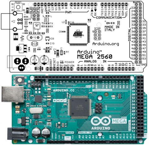
The research plan was based on the results of the authors' previous long-term studies [18-22]. The experimental study was carried out in the laboratory using a modern component base and the latest certified equipment. Investigation of functional characteristics of a linear DC voltage stabilizer AMS1117-0.5 [23] was performed as an integrated component to the Arduino Mega 2560 platform [6]. The boardview diagram and the general appearance of such a platform are presented in Figure 1.
Figure 1. Boardview diagram and general appearance of the microprocessor platform Arduino Mega
The following control and measuring devices were used to detect the electrical parameters of the investigated part of the circuit: for the parameters $U_{\text {in stabilizer }}$ and $U_{\text {out stabilizer }}$ – multimeter UT151C in the DC voltmeter mode; for the parameter $I_{\text {out stabilizer }}$– multimeter EM130 in the DC ammeter mode; for parameters $T_{\text {stabilizer }}$ and $T_{\text {microcontroller }}$– multimeter UT71C in the digital thermometer mode; for the parameter $T_{\text {surrounding }}$– multimeter MY62 in the digital thermometer mode. A two-channel laboratory power supply with a current stabilization function having an output voltage range from 0 to 30 V and an output current range from 0 to 5 A was used as a DC voltage source. The first stage of experimental tests involved using the following equipment as a laboratory load of the DC voltage stabilizer: sliding resistance rheostat SRR 3-93 with a value of 7 Ohm ± 20% and a permissible current of 7 A and sliding step rheostat SSR-0.4 with a value of 1 kOhm ± 20% and a permissible current of 0.4 A.
At the second stage of the experiment carbon tuning potentiometers of the RM063 series with a nominal value of 200 Ohm ± 10% were used as laboratory load of pins of the respective port groups, which were included in the rheostat circuit. MS Excel software was used for further processing and analysis of the obtained data.
The general algorithm of the experimental research on increase of reliability of Arduino Mega 2560 was divided into two main stages. During the first stage, the on-board power line was studied, which consists of a linear voltage stabilizer with a nominal power of 5 W and the corresponding components of electrical wiring. During the second stage, an experimental study of the operation of digital pins of the corresponding port groups of the microprocessor part was carried out with the optimal operating mode of the voltage stabilizer set at the first stage of testing.
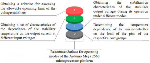
Figure 2. Diagram of the main stages of experimental tests
Figure 3. Photo of laboratory installation (A – block of control and measuring devices, B – tested microprocessor platform, C – block of loading of port groups)
Figure 2 shows a general diagram that reveals the sequence of experimental tests; Figure 3 shows a general view of the laboratory installation.
3.2 General research methods
The basis for achieving the goal is a comprehensive approach using: methods of critical analysis and logical generalization (section 2); methods of computerized monitoring of electrical parameters (experimental research, section 3); probability theory and mathematical statistics (processing and analysis of results, section 4); methods of experiment planning (experimental research, section 3); methods of computer analysis of measurement results (processing and analysis of results, section 4); approaches to experimental testing of information and measuring equipment (experimental research, Section 3).
3.3 Description of the first stage of the research
At the first stage of the experimental tests, temperature modes of the linear voltage stabilizer AMS1117-0.5 [23], which is part of the circuit of the five-volt power line of the microprocessor platform Arduino Mega 2560, were studied, which is shown in Figure 4.
Figure 4. Schematic electrical diagram of the five-volt power line of the investigated microcontroller board
To ensure the smooth operation of the electronic device, developed on the basis of the microprocessor platform Arduino Mega 2560, it is necessary to set the most efficient and long-term operation mode of the linear stabilizer.
The purpose of the first stage was to obtain a criterion according to which the load range should be limited. For this purpose, a series of measurements of operational electrical parameters of the studied circuit were performed to obtain data, which were used to establish a set of characteristics and to provide a quantitative assessment of each operation mode of the stabilizer within the microprocessor platform Arduino Mega 2560.
The primary task was to obtain values of the maximum allowable stabilizer temperature $T_{\text {stabilizer } \max }$, on the basis of which the load range of the power line was limited. The characteristics of the dependence of the stabilizer temperature $T_{\text {stabilizer }}$ on time t at the recommended input voltage of the stabilizer $U_{\text {in stabilizer }}=6.5 \mathrm{~V}$ and the output current of the stabilizer $I_{\text {out stabilizer }}=900 \mathrm{~mA}$ were also obtained.
The next task after obtaining the criterion (limiting temperature) was to conduct a series of measurements and obtain a set of characteristics of the dependence of the stabilizer temperature $T_{\text {stabilizer }}$ on the input voltage ${{U}_{in~stabilizer}}$ and the output current of the stabilizer $I_{\text {out stabilizer }}$. As a result, the values of the maximum allowable current at the input voltages of the stabilizer $U_{\text {in stabilizer }}=\{6.5 \mathrm{~V}, 7 \mathrm{~V}, 8 \mathrm{~V}, 9 \mathrm{~V}, 10 \mathrm{~V}, 11 \mathrm{~V}, 12 \mathrm{~V}\}$ were obtained provided that the maximum allowable temperature dissipated on the stabilizer chip $T_{\text {stabilizer } \max } \quad$ was not exceeded.
3.4 Description of the second stage of the research
The aim of the second stage of the experiment was to study the operating temperatures of the ATmega 2560 microcontroller during the operation of the respective port groups in the allowable load range.
Based on the analysis of the technical documentation [26] on the schematic implementation of the microprocessor, it was found that the ports and their pins are divided into appropriate groups. Each group has its own pair of power line pins. The general block diagram of the pins, ports and groups is shown in Figure 5.
Figure 5. Block diagram of grouping of ports and pins of the ATmega 2560 microcontroller
One of the main tasks to achieve the goal of the second stage of the experiment was to obtain characteristics of the dependence of the output current of the stabilizer $I_{\text {out stabilizer }}$, the stabilizer temperature $T_{\text {stabilizer }}$ and the microcontroller temperature $T_{\text {microcontroller }}$ on the number of simultaneously engaged pins of the corresponding ports $N_{\text {port }}$ when the output of the corresponding voltage port of the logic unit and the maximum allowable output current are set at one pin $I_{\text {out pin } \max }=40 \mathrm{~mA}$– for groups 1-3 and $I_{\text {out pin } \max }=20 \mathrm{~mA}$ – for group 4.
This was done to determine the maximum allowable number of simultaneously involved pins of the respective ports at different load modes of the circuit.
The loading of the pins of the respective port groups to the current limit value was performed according to the scheme shown in Figure 6.
Figure 6. Diagram of sequence of loading of group pins
The next task of the second stage of the study was to determine the dependence of the voltage stabilization of the logic level at the pin of the corresponding port on their serial and total load.
4.1 Limit operating parameters of the voltage stabilizer
To obtain quantitative estimates during the experimental tests, a series of direct measurements were performed, which were used to characterize the dependence of the stabilizer temperature $T_{\text {stabilizer }}$ on time t at the regulated values of the input voltage of the stabilizer $U_{\text {in stabilizer }}=6.5 \mathrm{~V}$ and the output current of the stabilizer $I_{\text {out stabilizer }}=900 \mathrm{~mA}$, as shown in Figure 7.
During the analysis of the obtained research results, which are shown in Figure 7, it was found that the maximum temperature during the action of the recommended values of input voltage and output current does not exceed temperature 85℃.
Figure 7. Dependences of stabilizer temperature on time at input voltage 6.5 V and output current 900 mA (S1-S4 – test series)
4.2 Temperature dependence of the voltage stabilizer
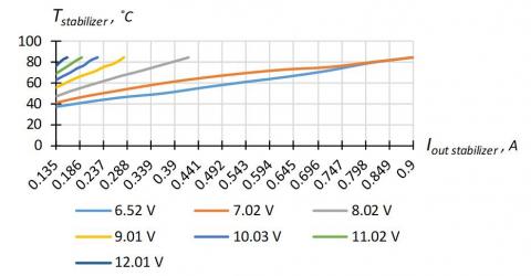
Thus, if the limit value of the stabilizer temperature is set and maintained at 85℃, which is the limit criterion of the nominal operation mode of the voltage stabilizer, we can get a set of characteristics of dependence of the stabilizer temperature on the output current at different input voltage values. This experiment will allow obtaining the maximum values of the allowable load of the stabilizer when powering electronic devices with the appropriate voltage. Then, limiting the value of the maximum allowable stabilizer temperature $T_{\text {stabilizer } \max }$, a set of characteristics of the temperature $T_{\text {stabilizer }}$ dependence on the output current $I_{\text {out stabilizer }}$ and input voltage $U_{\text {in stabilizer }}$ was determined. Based on such tests, the maximum allowable current at subsequent input voltages of the stabilizer $U_{\text {in stabilizer }}=\{6.5 \mathrm{~V}, 7 \mathrm{~V}, 8 \mathrm{~V}, 9 \mathrm{~V}, 10 \mathrm{~V}, 11 \mathrm{~V}, 12 \mathrm{~V}\}$ was obtained, as shown in Figure 8.
Based on the analysis of the data obtained, which are shown in Figure 8, it was found that with the input voltage increasing, the output current decreases. Therefore, when setting the required current at the output of the stabilizer for optimal operation, it is necessary to set the appropriate voltage at its input to limit the maximum heating temperature of the chip, which in turn reduces the probability of failure of the power line microprocessor platform Arduino Mega 2560.
Figure 8. Set of characteristics of the dependence of the stabilizer temperature
4.3 Characteristics of output voltage stabilization
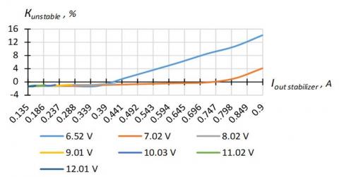
During the experimental tests, it was found that in some modes of operation the stabilizer does not meet the stated characteristics of voltage stabilization [23], as shown in Figure 9, in the form of the absolute deviation of the stabilization voltage from the nominal value (see Figure 9a) and the change in the relative instability coefficient $K_{\text {unstable }}$ (see Figure 9b), which is calculated by the formula:
$K_{\text {unstable }}=\frac{5.0-U_{\text {out stabilizer }}}{5.0} \cdot 100 \%$ (1)
where: $K_{\text {unstable }}$ is the relative coefficient of instability, %; Uout stabilizer $\mathrm{U}_{\text {out stabilizer }}$ is the actual voltage at the stabilizer output, V.
(a) absolute deviation of the stabilization voltage
(b) relative instability coefficient
Figure 9. Actual output voltage stabilization and relative instability coefficient
In the nominal operation mode at an input voltage of 6.5 V and an output current of 900 mA, the stabilizer does not meet the requirements for stabilization of the output voltage within the allowable limits of ±35 mV [23]. In this mode, the voltage at the stabilizer output drops to 4.29 V. According to the experimental tests, it can be concluded that the optimal operation mode is achieved at an input voltage in the range from 7 to 7.5 V. In this mode at an output current of 900 mA the temperature does not exceed 85℃ and the stabilization voltage corresponds to the stated characteristics and is equal to 4.8 V, as shown in Figure 9.
Based on the analysis of the research results shown in Figure 9, it should be recommended that during the development of electronic devices that require a supply voltage of 6.5 V and the stabilization parameter is not critical, it is allowed to reduce the stabilization voltage to 4.29 V. In this mode, it should be taken into account that the supply voltage of the microprocessor part will be 4.29 V and the logic levels will not correspond to most compatible devices. It should also be considered that the reference voltage of the analogue-to-digital converter (ADC) will also be lower and when designing information and measurement systems using analogue sensors it is necessary to use an external reference voltage source or take this fact into account when processing output data from the ADC.
4.4 Temperature dependence of the microcontroller
The next stage of the research was to conduct a series of measurements of the microcontroller temperature and voltage at the pins of the respective groups of ports under sequential loading.
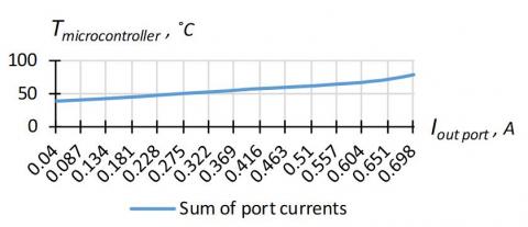
As a result, the characteristic of the microcontroller temperature dependence on the number of simultaneously engaged digital ports of the Arduino Mega 2560 board at a fixed consumption current and the total allowable current at the corresponding digital pins was obtained. According to the data obtained when the output groups were loaded with a total current of 700 mA, it was found that the maximum temperature of the microcontroller did not exceed 80℃, which corresponds to the normal temperature of the microcontroller operation. The dependence of the microcontroller temperature on the total output current at the port pins is shown in Figure 10.
Figure 10. Dependence of microcontroller temperature on the total current on digital ports
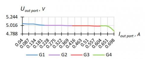
According to the results of a series of measurements, the dependences of the stabilization voltage of the respective pins under load were established, which is presented in Figure 11.
(a) A0-A7, G2, J0-J7 (A0-A4)
(b) B0-B7, G3-G4, H0-H7 (B3-B7)
(c) C0-C7, D0-D7, G0-G1, L0-L7 (C3-C7)
(d) E0-E7, G5 (E0-E1, E3-E5)
Figure 11. Dependences of voltage of stabilization of the corresponding pins under loading
The graphs show the dependence of the voltage stabilization level of the logic unit of the corresponding port groups on their load:
- Figure 11a – level of voltage stabilization of the logic unit at the pin of group 1 with a series load of groups 1 - 4;
- Figure 11b – level of voltage stabilization of the logic unit at the pin of group 2 with a series load of groups 1 - 4;
- Figure 11c – level of voltage stabilization of the logic unit at the pin of group 3 with a series load of groups 1 - 4;
- Figure 11d – level of voltage stabilization of the logic unit at the pin of group 4 with a series load of groups 1 - 4.
According to the obtained data, it is possible to draw a conclusion about the possible number of simultaneously involved pins of the corresponding group of ports at the maximum consumption current on one pin of 40 mA [6].
If the pins are used in the limit mode of 40 mA, the value of the total allowable current at the output of the port group is achieved by simultaneously using five pins for groups 1 - 3 and two pins when loading groups 4 - 5 (the fifth group is analogue pins of the microcontroller). In this case, the level of voltage stabilization on the port group decreases from 5.07 V to 4.8 V.
It should also be noted that such voltage decrease is observed only on the loaded port group. The level of voltage stabilization at the pins of other groups remains unchanged. From this we can conclude that it is possible to simultaneously use the appropriate group of ports for different types of devices, namely: information interfaces, control devices or indicators.
The scientific novelty of the obtained results lies in the determination of the criterion for assessing the performance characteristics of budget serial microprocessor platforms and the development of methods to ensure their reliable operation. It was determined that the stabilizer temperature, acts as an integral criterion for reliable operation of the power supply line of the microprocessor platform. The practical significance of the research results lies in the substantiation of recommendations for optimal load modes of budget serial microcontroller boards of Arduino Mega 2560 type. Based on this, the permissible range of load currents has been established, as well as the allowable stabilizer temperature range has been evaluated.
Promising areas of further research in the claimed subject area are: adaptation of the obtained results to specific types of devices with standardized interfaces, which are the load of the microprocessor platform; scaling the obtained results to other types of budget serial microcontroller boards; long-term tests of budget serial microcontroller boards in real production conditions taking into account the received recommendations on their loading.
The article has achieved the main purpose of the research to substantiate scientific approaches to increasing the reliability of budget serial microcontroller boards during their operation as part of computerized information and measurement systems. The result obtained in the article allows to substantiate the recommendations for the operation of the Arduino microprocessor platform under different load modes. This fact allows to increase the reliability of computerized information measuring systems based on Arduino. The main scientific and practical results are as follows:
- the current state of scientific research and practical developments on ways to improve the technical and functional characteristics of the serial budget microprocessor platforms was analysed;
- it was determined that the stabilizer temperature, which should not exceed 85℃, acts as an integral criterion for reliable operation of the power supply line of the microprocessor platform;
- the stabilization characteristics of the output voltage of the microprocessor platform were obtained, which allowed establishing the optimal supply voltage being in the range from 7 V to 7.5 V;
- the characteristics of the microcontroller temperature dependence were obtained, which allowed substantiating a number of recommendations for the operation of the microprocessor platform Arduino Mega 2560 at different denominations and types of loads;
- the priority areas for further research were substantiated, which will allow deepening and expanding the scope of implementation of budgetary serial microcontroller boards.
|
Iout pin |
current at the pin output, mA |
|
Iout pin max |
maximum current at the pin output, mA |
|
Iout port |
current at the port output, mA |
|
Iout stabilizer |
current at the stabilizer output, mA |
|
Kunstable |
relative instability coefficient, % |
|
Nport |
number of ports |
|
t |
time, s |
|
Tmicrocontroller |
microcontroller temperature, ℃ |
|
Tstabilizer |
stabilizer temperature, ℃ |
|
Tstabilizer max |
maximum stabilizer temperature, ℃ |
|
Tsurrounding |
ambient temperature, ℃ |
|
Uin stabilizer |
voltage at the stabilizer input, V |
|
Uout pin |
voltage at the pin output, V |
|
Uout port |
voltage at the port output, V |
|
Uout stabilizer |
voltage at the stabilizer output, V |
|
Abbreviations |
|
|
ADC |
Analogue to digital converters |
|
IoT |
Internet of things |
|
IT |
Information Technology |
|
WSN |
Wireless sensor network |
[1] Mukhopadhyay, S.C., Suryadevara, N.K. (2014). Internet of things: Challenges and opportunities. In Internet of Things, 9: 1-17. https://doi.org/10.1007/978-3-319-04223-7_1
[2] Begum, K., Dixit, S. (2016). Industrial WSN using IoT: A survey. In 2016 International Conference on Electrical, Electronics, and Optimization Techniques (ICEEOT). pp. 499-504. https://doi.org/10.1109/iceeot.2016.7755660
[3] Ud Din, I., Guizani, M., Hassan, S., Kim, B.S., Khan, M., Atiquzzaman, M., Ahmed, S. (2018). The internet of things: A review of enabled technologies and future challenges. IEEE Access, 7: 7606-7640. https://doi.org/10.1109/ACCESS.2018.2886601
[4] Alphonsusa, E.R., Abdullah, M.O. (2016). A review on the applications of programmable logic controllers (PLCs). Renewable and Sustainable Energy Reviews, 60: 1185-1205. https://doi.org/10.1016/j.rser.2016.01.025
[5] Hudedmani, M., Umayal, R., Kabberalli, S., Hittalamani, R. (2017). Programmable logic controller (PLC) in automation. Advanced Journal of Graduate Research, 2(1): 37-45. https://doi.org/10.21467/ajgr.2.1.37-45
[6] Arduino. (2021). URL: https://www.arduino.cc/en/Main/Products.
[7] Tatović, M., Milovanović, A., Karapandžić, I. (2016). Device for the remote measurement of meteorological data based on Arduino platform. Serbian Journal of Electrical Engineering, 13(1): 133-144. https://doi.org/10.2298/SJEE1601133T
[8] Suganthi Jemila, J., Suja Priyadharsini, S. (2018). A sensor-based forage monitoring of grazing cattle in dairy farming. International Journal on Smart Sensing and Intelligent Systems, 11(1): 1-9. https://doi.org/10.21307/ijssis-2018-014
[9] Akhter, F., Siddiquei, H.R., Alahi, M.E.E., Mukhopadhyay, S.C. (2021). Recent advancement of the sensors for monitoring the water quality parameters in smart fisheries farming. Computers, 10(26): 1-20. https://doi.org/10.3390/computers10030026
[10] Oliveira-Jr, A., Resende, C., Pereira, A., Madureira, P., Goncalves, J., Moutinho, R., Soares, F., Moreira, W. (2020). IoT sensing platform as a driver for digital farming in rural Africa. Sensors, 20(3511): 1-25. https://doi.org/10.3390/s20123511
[11] Vovna, O., Laktionov, I., Koyfman, O., Stashkevych, I., Lebediev, V. (2020). Study of metrological characteristics of low-cost digital temperature sensors for greenhouse conditions. Serbian Journal of Electrical Engineering, 17(1): 1-20. https://doi.org/10.2298/SJEE2001001V
[12] Louis, L. (2016). Working principle of Arduino and using it as a tool for study and research. International Journal of Control, Automation, Communication and Systems, 1(2): 21-29. http://doi.org/10.5121/ijcacs.2016.1203
[13] Baranski, R., Galewski, M., Nitkiewicz, S. (2020). The study of Arduino Uno feasibility for DAQ purposes. Diagnostyka, 20(2): 33-48. https://doi.org/10.29354/diag/109174
[14] Shirsath, D.O., Kamble, P., Mane, R., Kolap, A., More, R.S. (2017). IoT based smart greenhouse automation using Arduino. International Journal of Innovative Research in Computer Science & Technology, 5(2): 234-238. https://doi.org/10.21276/ijircst.2017.5.2.4
[15] Beddows, P., Mallon, E. (2018). Cave pearl data logger: A flexible Arduino-based logging platform for long-term monitoring in harsh environments. Sensors, 18(2): 1-26. https://doi.org/10.3390/s18020530
[16] Vimal, P.V., Shivaprakasha, K.S. (2017). IoT based greenhouse environment monitoring and controlling system using Arduino platform. In 2017 International Conference on Intelligent Computing, Instrumentation and Control Technologies (ICICICT), pp. 1514-1519. https://doi.org/10.1109/ICICICT1.2017.8342795
[17] Candelas, F.A., Garcia, G.J., Puente, S., Pomares, J., Jara, C.A., Perez, J., Mira, D., Torres, F. (2015). Experiences on using Arduino for laboratory experiments of automatic control and robotics. IFAC-Papers on Line, 48(29): 105-110. https://doi.org/10.1016/j.ifacol.2015.11.221
[18] Vovna, O., Laktionov, I., Sukach, S., Kabanets, M., Cherevko, E. (2018). Method of adaptive control of effective energy lighting of greenhouses in the visible optical range. Bulgarian Journal of Agricultural Science, 24(2): 335-340.
[19] Vovna, O., Laktionov, I., Bashkov, E., Akhmedov, R., Zori, A. (2018). Development of software component of the optical methane concentration meter based on LabVIEW. Journal of Engineering Science and Technology, 13(12): 3932-3950.
[20] Vovna, O., Laktionov, I., Andrieieva, A., Petelin, E., Shtepa, O., Laktionova, H. (2019). Optimized calibration method for analog parametric temperature sensors. Instrumentation Mesure Metrologie, 18(6): 517-526. https://doi.org/10.18280/i2m.180602
[21] Laktionov, I.S., Vovna, O.V., Bashkov, Y.O., Zori, A.A., Lebediev, V.A. (2019). Improved computer-oriented method for processing of measurement information on greenhouse microclimate. International Journal Bioautomation, 23(1): 71-86. https://doi.org/10.7546/ijba.2019.23.1.71-86
[22] Vovna, O.V., Laktionov, I.S., Dobrovolska, L.O., Kabanets, M.M, Lebediev, V.A. (2019). Evaluation of metrological characteristics of a computerized conductivity meter of irrigation solution based on the uncertainty theory. Journal Europeen des Systemes Automatises, 52(4): 333-340. https://doi.org/10.18280/jesa.520401
[23] Advanced Monolithic Systems. (2021). URL: https://datasheet.lcsc.com/szlcsc/2012311032_Slkor-SLKORMICRO-Elec-AMS1117-5-0_C473812.pdf.
[24] Franzone, J. (2001). A laboratory experiment in linear series voltage regulators. In: 2001 Annual Conference, Indianapolis, pp. 1-60. https://peer.asee.org/a-laboratory-experiment-in-linear-series-voltage-regulators.pdf.
[25] Bajenaru, A., Boianceanu, C., Brezeanu, G. (2013). Investigation of electro-thermal behaviour of a linear voltage regulator and its protection circuits by simulator coupling. In: CAS 2013 International Semiconductor Conference, Sinaia, pp. 237-240. https://doi.org/10.1109/SMICND.2013.6688665
[26] Microchip. (2021). URL: https://ww1.microchip.com/downloads/en/DeviceDoc/ATmega640-1280-1281-2560-2561-Datasheet-DS40002211A.pdf.