Deepak Bharadwaj* | Durga Dutt
© 2021 IIETA. This article is published by IIETA and is licensed under the CC BY 4.0 license (http://creativecommons.org/licenses/by/4.0/).
OPEN ACCESS
Pneumatics suction is being used in the food factory for picking and placing the ingredients of food. A clean environment inside the food factory is very much needed the maintain the quality of packaging food. The present work focuses on the low level of automation so that investment cost for processing the raw ingredient goes down. Two double-acting pneumatic cylinders, one pneumatic suction gripper, three pneumatic direction control valves, one screw compressor, one DC motor, two relays, a Push button, and a 24-volt power supply have been used the implement the system. A combination of pneumatic actuation and electrical actuation is used for controlling the motion of the system. A simple control ON/OFF system was used for the actuation. Pneumatic component drive with the help of compressed air via a direction control valve and motor direction control using the relay. By pressing the push button whole, the setup can be controlled in a very easier way and it is very user-friendly for the operator. Several testings have been done on the setup and an excellent result were obtained during execution.
pneumatic actuator, pneumatic suction, gripper, relay
Food processing and food production are very large employment sectors globally. The advancement in sensors, actuators, and electronics components, completely replaced the manual operation with the advanced automated food processing operation. The consumption of packaged food products was increasing globally. The automation line is fulfilling the demand for food products [1]. In the current scenario, industry focus shifted toward the taste and quality of the food product. The role of automation in the product layout is much more needed for the global optimization of production facilities. Safety and environmental protection are also very much critical to the worker and the environment [2]. The latest trends in food manufacturing have experienced exponential growth and become a potential contributor to the economy. The large industrial manufacturing company has an advanced automated line for food processing. But the low-level food supplier was not using the automation line for the food proceeding due to the higher investment cost of the automation line [3]. The economies of the undeveloped countries are increasing these days, the consumers demanded processed food as compared to staples. The worldwide food product business was reached multi-trillion of dollars and 16 million people were involved in this business. A high-end automation setup was contributing to a large market [4]. One of the main issues in the foodservice industry in food safety and contamination. The food industry is responsible for public health and safety. Airborne particles, dust, metal contamination, and people interaction are arising the problem for the food product [5]. Hydraulic system actuation also arises the hygienic issues to the food product. Oil mixed with the food ingredients and there is a chance of a taste of the food product will change. The hydraulic system was not a full-proof leakage system. Oil is coming out from the piston-cylinder surfaces and the pipe surface. These oils will be mixed with the ingredients. A more hygienic and cleaner environment is needed for the food industry. The food industry shifted towards pneumatic systems. Air is cleaner as compared to other modes of a working fluid. Even though the cleaner air is mixed with the food ingredients, there are no chances of quality and hyenic issues. Based on the different health issues and hygienic issues, a pneumatic system setup and drive were considered for the present work.
1.1 Research gap
After a detailed literature review, it was found that the large-scale food industry was implemented the advanced automated line for food processing and food production. The low-scale food industry and the individual were not able to implement the automation line for the food processing due to the high cost of investment setup. The present work focuses on low-cost automation development so that it can boost up food processing and hygienic issues of food production.
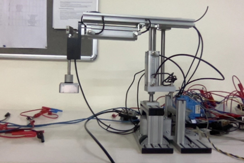
A manipulator is a device that consists of joints, links, and the end effector. The manipulator motion was controlled with the help of different types of actuation systems like electrical motor, pressurized hydraulic oil, and compressed air. The main component of a pneumatic manipulator is a double-acting pneumatic cylinder. A double-acting pneumatic cylinder is a device that converts the pressurized energy into motion with the help of other pneumatic components. The pneumatic actuator has mainly three parts. The pneumatic cylinder consists of a piston-cylinder arrangement inside the casing [6]. Pneumatic Manipulator consists of two double-acting pneumatic cylinders, one DC motor at the base, and one pneumatic gripper [7]. The pneumatic manipulator has three degrees of freedom. One DOF at the base i.e. Revolute in nature. The second and third DOF is prismatic. Both the double-acting pneumatic cylinder were supported by the column and the base motor is supported on the platform and with the help of bevel gear motion is transmitted from one plane to another plane. Complete details of the pneumatic cylinder were shown in Figure 1.
Figure 1. Pneumatic manipulator
The maximum stroke of both the double-acting pneumatic cylinder is depicted in Table 1.
Table 1. Pneumatic manipulator parameter
|
S.No |
Description |
Stroke length |
|
1 |
Pneumatic Cylinder 1 |
0-70 mm |
|
2 |
Pneumatic Cylinder 2 |
0-100 mm |
|
3 |
Pneumatic Suction |
2 mm |
|
4 |
DC Motor |
0-90° |
Figure 2. Frame assignment for RPP manipulator
The kinematic model describes the spatial position of joints and links, also the position and orientation of the end effector [8]. The derivatives of the kinematic model deal with the mechanics of motion without considering the forces that cause it. The kinematic model is the analytical description of the spatial geometry of the motion of the manipulator to a fixed reference frame, as a function of time. The definition of a manipulator with four joint–link parameters for each link and a systematic procedure for assigning right-handed orthonormal coordinate frames, one to each link in an open kinematic chain, was proposed by Denavit-Hartenberg notation [9]. Denavit-Hartenberg method is used to calculate the workspace of a pneumatic manipulator. All the joints and links are identified and labeled from 1 to 3 respectively. The complete frame assignment is shown in Figure 2 from which all the joint-link parameters are determined and tabulated in Table 2. Applying the algorithm of Denavit-Hartenberg step by step, the transformation matrix of each joint can be calculated [10]
Table 2. DH parameters for RPR Manipulator
|
DH Parameters |
Link |
||
|
|
1 |
2 |
3 |
|
θi |
θ1 |
0 |
0 |
|
di |
0 |
l1 |
l2 |
|
ai |
0 |
0 |
0 |
|
αi |
0 |
0 |
90 |
Now, the individual transformation matrices that specify the relationship between adjacent links as below:
${ }_{1}^{0} T={Rot}\left(z, \theta_{1}\right) * {Trans}(0,0,0) * {Trans}(0,0,0) * {Rot}(x, 0)$ (1)
${ }_{2}^{1} T={Rot}\left(z, 0\right) * {Trans}(0,0,l_1) * {Trans}(0,0,0) * {Rot}(x, 0)$ (2)
${ }_{3}^{2} T={Rot}\left(z, 0\right) * {Trans}(0,0,l_2) * {Trans}(0,0,0) * {Rot}(x, 0)$ (3)
where, ${ }_{i}^{i-1} T$ is a general link transformation matrix relating the i-th coordinate frame to the ( i-1)th coordinate frame.
The workspace created by the RPR pneumatic Manipulator was obtained
${ }_{3}^{0} T={ }_{1}^{0} T^{* }{ }_{2}^{1} T^{* }{ }_{3}^{2} T=\left[\begin{array}{cccc}r_{11} & r_{12} & r_{13} & \boldsymbol{r}_{14} \\ r_{21} & r_{22} & r_{23} & \boldsymbol{r}_{24} \\ r_{31} & \boldsymbol{r}_{32} & \boldsymbol{r}_{33} & \boldsymbol{r}_{34} \\ 0 & 0 & 0 & 1\end{array}\right]$$=\left[\begin{array}{cccc}\cos \left(\theta_{1}\right) & \sin \left(\theta_{1}\right) & 0 & l_{2} \sin \left(\theta_{1}\right) \\ \sin \left(\theta_{1}\right) & -\cos \left(\theta_{1}\right) & 0 & -l_{2} \cos \left(\theta_{1}\right) \\ 0 & 0 & -1 & l_{1} \\ 0 & 0 & 0 & 1\end{array}\right]$ (4)
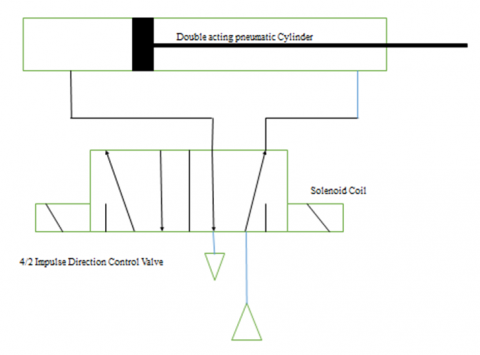
A 5 bar compressed air is used to operate the extension and retraction stroke of a double-acting pneumatic cylinder. Also, the partial vacuum was created by the retraction of the piston inside the cylinder. The pneumatic suction was also created with the help of pressurized air. Figure 3 shows the pneumatic circuit diagram of the double-acting pneumatic cylinder and pneumatic suction using an impulse valve [11].
The piston rod of the double-acting cylinder extends when the push-button is pressed momentarily. The piston rod remains extended until the opposite command retract follows by briefly actuating another push button. The pushbuttons switch the valve solenoids indirectly via relay contacts.
Figure 3. Pneumatic circuit for actuation
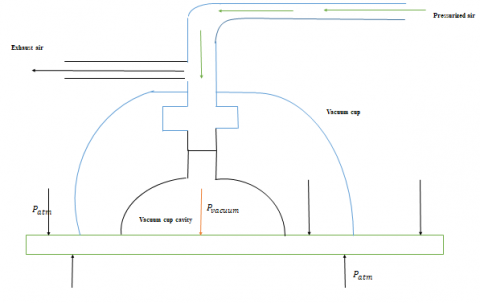
4.1 Pneumatic suction
Figure 4 shows vacuum cup is used to establish the force capability to lift the flat sheet. The cup is made of a flexible material such as rubber so that a seal can be made where its lip contacts the surfaces of the flat surface of the flat sheet. The pressurized air enters from one port and escapes out from the other port as shown in Figure 4. The air molecule present to the inner layer of pneumatic suction assembly, try to come out and it creates a partial vacuum. The magnitude of the force is determined by algebraically summing the pressure forces on the top and bottom surfaces of the flat surface [12].
$F=p_{ {atm }} A_{o}-p_{ {suction }} A_{i}$ (5)
where, F=the upward force the suction cup exerts on the flat sheet.
$p_{ atm }$= the atmospheric pressure in absolute.
$A_{o}$=the area of the outer circle of the suction cup.
$A_{i}$= the area of the inner circle of the suction cup.
$p_{ suction }$= suction pressure.
Figure 4. Vacuum cup used to lift a flat sheet
When a perfect vacuum exists, the maximum lift force is produced. The exact amount of suction pressure developed cannot be guaranteed, and the resulting suction force must be at least as large as the weight of an object to be lifted. A factor of safety is applied [13].
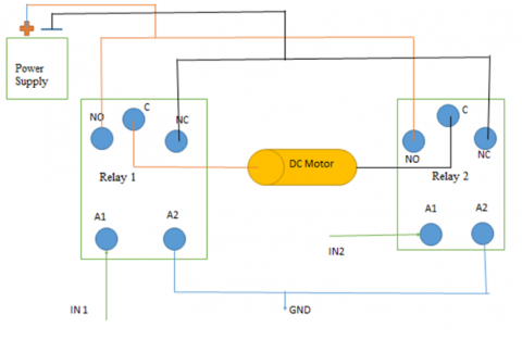
The base motor direction was controlled with the help of two relays. In this work, no motor drivers were used. In place of the motor driver, a relay concept had been introduced to control the clockwise and anticlockwise movement of the motor. Figure 5 shows the electrical circuit diagram for the control of the DC motor [14].
Figure 5. Motor control using relay
The positive and negative terminals of the DC motor were connected between the common terminals of both the relay. The positive terminal of the power supply is connected at NO (Normally open) contactor and the negative supply is connected at NC (Normally closed) contactor. The clockwise and counterclockwise were controlled by supplied at IN1 (Input 1) and IN2 (Input2). A solenoid is controlling the direction flows of compressed air by shifting the poppet inside the DCV.
Both valve solenoids Y1 and Y2 and the two relay coils are connected to the 0V potential at the bottom bus bar. Push-button S1 in current path 1 controls relay K1, the normally open contact K1 in current path 3 switches the valve solenoid Y1. When push button S2 in current path 2 is actuated, relay K2 switches, the normally open contract K2 in current path 4 switches the valve solenoid Y2. Figure 6 shows the electrical circuit diagram for controlling the solenoid coil via relay.
Figure 6. Electrical circuit
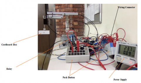
A synergistic integration was established between the different sub-components. The experimental setup consists of the two double-acting pneumatic cylinders, pneumatic suction cup, impulse DCV, DC Motor, Relay, and push button. Figure 7 shows the schematic setup of each component. A low level of automation can be implemented for picking and placing the operation. Figure 8 shows the complete setup of the system after integrating each component [15].
Figure 7. Set-up
Figure 8. Experimental setup
6.1 Testing
Several experiments were carried out on the pneumatic manipulator. Some experiments were carried out on the 5 bar pressure and other experiments were carried out at a different range of pressure. Suction cup testing was also done on the cardboard box and metallic element. The setup was successfully picking the object and there is no interference were observed during the experimentation. The sequential operation of the pneumatic operation is listed in Table 3.
Table 3. Sequential operation action
|
S.No |
Push Button |
Component |
Action |
|
1 |
S1 |
Pneumatic Cylinder 1 |
Extension |
|
2 |
S2 |
Pneumatic Cylinder 1 |
Retraction |
|
3 |
S3 |
Pneumatic Cylinder 2 |
Extension |
|
4 |
S4 |
Pneumatic Cylinder 2 |
Retraction |
|
5 |
S5 |
Pneumatic Suction |
Start |
|
6 |
S6 |
Pneumatic Suction |
Stop |
|
7 |
S7 |
DC Motor |
Clockwise |
|
8 |
S8 |
DC Motor |
Counterclockwise |
The motion of the pneumatic cylinder was observed very smooth. Some of the positions were recorded during the experimentation as shown in the Figure 9 & Figure 10.
Figure 9. Initial position
Figure 10. Final position
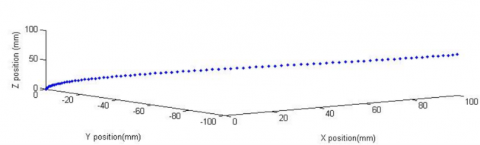
After integrating the different components of the system, the theoretical workspace evaluated by the mathematical expression was verified at a different orientation. The stroke length of the pneumatic cylinder was varied from 0 to 70mm, the stroke length of the pneumatic cylinder was varied from 0 to 100mm and the theta1 varies from 0 degrees to 90 degrees. The workspace generated by the mathematical expression was validated with real-time experimentation. The workspace created by the pneumatic manipulator as shown in the Figure 11 and the same thing were validated. The cardboard sized were varied from 5gram to 50 gram in the weight. The pneumatic suction force was measured with the help of load cell. The variation of suction force was observed during experimentation and found that the magnitude was varies from 0.8 Newton to 1.2 Newton. By changing the weight of cardboard, the effect of current was also observed. DC motor draws the current form power circuit from 1.1 Ampere to 1.5 Ampere. No interior singularity was occurring during the testing and experimentation.
Figure 11. Workspace generated by pneumatic manipulator
The high investment cost setup, quality of food and hygienic issues were considered in food processing at the individual level. A low level control system had been adopted for the operation of pneumatic manipulator. The 5-bar compressed air, which is cleaner medium, were used for the movement of the pneumatic manipulation. An individual could control the pneumatic manipulation system using the push button operation. A low level of automation was established among the different components.
We would to very thankful to the Mechanical engineering Department of UPES for giving support to carrying out this work.
|
θi |
Joint angle |
|
di |
Joint offset |
|
ai |
Link length |
|
αi |
Link twist |
|
S1 |
Push stop button 1 |
|
S2 |
Push stop button 2 |
|
K1 |
Relay coil 1 |
|
K2 |
Relay coil 2 |
|
k1 |
Relay contactor 1 |
|
k2 |
Relay contactor 2 |
|
Y1 |
Solenoid coil 1 |
|
Y2 |
Solenoid coil 2 |
|
A1 |
Positive terminal of relay coil |
|
A2 |
Negative terminal of relay coil |
|
NO |
Normally open contactor of relay |
|
NC |
Normally closed contactor of relay |
|
C |
Common terminal of relay |
|
IN1 |
Input from operator |
|
IN2 |
Input from operator |
|
DCV |
Direction control valve |
|
RPP |
Revolute prismatic prismatic |
|
θ1 |
Joint angle 1 |
|
l1 |
Maximum stroke movement of pneumatic cylinder 1 |
|
l2 |
Maximum stroke movement of pneumatic cylinder 2 |
|
${ }_{1}^{0} T$ |
Transformation of joint 1 with respect to joint 0 |
|
${ }_{2}^{1} T$ |
Transformation of joint 2 with respect to joint 1 |
|
${ }_{3}^{2} T$ |
Transformation of joint 3 with respect to joint2 |
|
${ }_{3}^{0} T$ |
Transformation of joint 3 with respect to joint 0 |
${ }_{1}^{0} T={Rot}\left(z, \theta_{1}\right) * {Trans}(0,0,0) * {Trans}(0,0,0) * {Rot}(x, 0)=\left[\begin{array}{cccc}\cos \theta_{1} & -\sin \theta_{1} & 0 & 0 \\ \sin \theta_{1} & \cos \theta_{1} & 0 & 0 \\ 0 & 0 & 1 & 0 \\ 0 & 0 & 0 & 1\end{array}\right] *\left[\begin{array}{cccc}1 & 0 & 0 & 0 \\ 0 & 1 & 0 & 0 \\ 0 & 0 & 1 & 0 \\ 0 & 0 & 0 & 1\end{array}\right]$
$\left[\begin{array}{cccc}1 & 0 & 0 & 0 \\ 0 & 1 & 0 & 0 \\ 0 & 0 & 1 & 0 \\ 0 & 0 & 0 & 1\end{array}\right] *\left[\begin{array}{cccc}1 & 0 & 0 & 0 \\ 0 & 1 & 0 & 0 \\ 0 & 0 & 1 & 0 \\ 0 & 0 & 0 & 1\end{array}\right]=\left[\begin{array}{cccc}\cos \theta_{1} & -\sin \theta_{1} & 0 & 0 \\ \sin \theta_{1} & \cos \theta_{1} & 0 & 0 \\ 0 & 0 & 1 & 0 \\ 0 & 0 & 0 & 1\end{array}\right]$
${ }_{2}^{1} T={Rot}(z, 0) * {Trans}\left(0,0, l_{1}\right) * {Trans}(0,0,0) * {Rot}(x, 0)=\left[\begin{array}{cccc}1 & 0 & 0 & 0 \\ 0 & 1 & 0 & 0 \\ 0 & 0 & 1 & 0 \\ 0 & 0 & 0 & 1\end{array}\right] *\left[\begin{array}{cccc}1 & 0 & 0 & 0 \\ 0 & 1 & 0 & 0 \\ 0 & 0 & 1 & l_{1} \\ 0 & 0 & 0 & 1\end{array}\right]$
$\left[\begin{array}{llll}1 & 0 & 0 & 0 \\ 0 & 1 & 0 & 0 \\ 0 & 0 & 1 & 0 \\ 0 & 0 & 0 & 1\end{array}\right] *\left[\begin{array}{llll}1 & 0 & 0 & 0 \\ 0 & 1 & 0 & 0 \\ 0 & 0 & 1 & 0 \\ 0 & 0 & 0 & 1\end{array}\right]=\left[\begin{array}{llll}1 & 0 & 0 & 0 \\ 0 & 1 & 0 & 0 \\ 0 & 0 & 1 & l_{1} \\ 0 & 0 & 0 & 1\end{array}\right]$
${ }_{3}^{2} T=\operatorname{Rot}(z, 0) * \operatorname{Trans}\left(0,0, l_{2}\right) * \operatorname{Trans}(0,0,0) * \operatorname{Rot}(x, 0)=\left[\begin{array}{cccc}1 & 0 & 0 & 0 \\ 0 & 1 & 0 & 0 \\ 0 & 0 & 1 & 0 \\ 0 & 0 & 0 & 1\end{array}\right] *\left[\begin{array}{cccc}1 & 0 & 0 & 0 \\ 0 & 1 & 0 & 0 \\ 0 & 0 & 1 & l_{2} \\ 0 & 0 & 0 & 1\end{array}\right]$
$\left[\begin{array}{llll}1 & 0 & 0 & 0 \\ 0 & 1 & 0 & 0 \\ 0 & 0 & 1 & 0 \\ 0 & 0 & 0 & 1\end{array}\right] *\left[\begin{array}{llll}1 & 0 & 0 & 0 \\ 0 & 1 & 0 & 0 \\ 0 & 0 & 1 & 0 \\ 0 & 0 & 0 & 1\end{array}\right]=\left[\begin{array}{cccc}1 & 0 & 0 & 0 \\ 0 & 1 & 0 & 0 \\ 0 & 0 & 1 & l_{2} \\ 0 & 0 & 0 & 1\end{array}\right]$
${ }_{3}^{0} T={ }_{1}^{0} T^{* }{ }_{2}^{1} T^{* }{ }_{3}^{2} T=\left[\begin{array}{cccc}\cos \left(\theta_{1}\right) & \sin \left(\theta_{1}\right) & 0 & l_{2} \sin \left(\theta_{1}\right) \\ \sin \left(\theta_{1}\right) & -\cos \left(\theta_{1}\right) & 0 & -l_{2} \cos \left(\theta_{1}\right) \\ 0 & 0 & -1 & l_{1} \\ 0 & 0 & 0 & 1\end{array}\right]$
[1] Davis, S., King, M.G., Casson, J.W., Gray, J.O., Caldwell, D.G. (2007). End effector development for automated sandwich assembly. Meas. Control, 40(7): 202-206. https://doi.org/10.1177/002029400704000701
[2] Tommila, T., Ventä, O., Koskinen, K. (2015). Next Generation Industrial Automation. Automation Technology Review. Corpus ID:115506406.
[3] Ilyukhin, S.V., Haley, T.A., Singh, R.K. (2001). A survey of automation practices in the food industry. Food Control, 12(5): 285-296. https://doi.org/10.1016/S0956-7135(01)00015-9
[4] Cheruvu, P., Kapa, S., Mahalik, N.P. (2008). Recent advances in food processing and packaging technology. International Journal of Automation and Control, 2(4): 418-435. http://dx.doi.org/10.1504/IJAAC.2008.022894
[5] Massaro, A., Galiano, A. (2020). Re-engineering process in a food factory: An overview of technologies and approaches for the design of pasta production processes. Prod. Manuf. Res., 8(1): 80-100. https://doi/org/10.1080/21693277.2020.1749180
[6] Jiménez, M., Kurmyshev, E., Castañeda, C.E. (2020). Experimental study of double-acting pneumatic cylinder. Exp. Tech., 44(3): 355-367. https://doi/org/10.1007/s40799-020-00359-8
[7] van Damme, M., Daerden, F., Lefeber, D. (2005). A pneumatic manipulator used in direct contact with an operator. Proceedings of the 2005 IEEE International Conference on Robotics and Automation, 2005, pp. 4494-4499. https://doi/org/10.1109/ROBOT.2005.1570812
[8] Gupta, A., Mondal, A.K., Gupta, M.K. (2019). Kinematic, dynamic analysis and control of 3 DOF Upper-limb robotic exoskeleton. Journal Européen des Systèmes Automatisés, 52(3): 297-304. https://doi.org/10.18280/jesa.520311
[9] Corke, P.I. (2002). A simple and systematic approach to assigning denavit–hartenberg parameters. IEEE Trans. Robot., 48(4): 766-769. https://doi/org/10.1109/TPAMI.2012.125
[10] Bharadwaj, D., Prateek, M. (2019). Kinematics and dynamics of lower body of autonomous humanoid biped robot. Int. J. Innov. Technol. Explor. Eng., 8(4): 141-146.
[11] Brick, P., Histories, L. (2021). Relay control of a morphing tensegrity structure with distributed pneumatic actuation. 9th Int. Conf. Fluid Power Transaction. Control. Hangzhou, China, pp. 1-42.
[12] Kurpaska, S., Sobol, Z., Pedryc, N., Hebda, T., Nawara, P. (2020). Analysis of the pneumatic system parameters of the suction cup integrated with the head for harvesting strawberry fruit. Sensors, 20(16): 4389. https://doi/org/10.3390/s20164389
[13] Shin, H.Y., Lee, J.W. (1998). An expert system for pneumatic design. Artif. Intell. Eng. Des. Anal. Manuf., 12(1): 3-11. https://doi/org/10.1017/S0890060498121121
[14] Fridman, L.M., Shustin, E.I., Fridman, E.M. (1997). Steady modes in the relay control systems with time delay and periodic disturbances. Int. Conf. Control Oscil. Chaos, Proc., 1: 75-78. https://doi/org/10.1109/coc.1997.633485
[15] Leitao, P., Karnouskos, S., Ribeiro, L., Moutis, P., Barbosa, J., Strasser, T.I. (2017). Common practices for integrating industrial agents and low level automation functions. Proc. IECON 2017 - 43rd Annual. Conf. IEEE Ind. Electron. Soc., pp. 6665-6670. https://doi/org/10.1109/IECON.2017.8217164