Rahul Wilson Kotla* | Srinivasa Rao Yarlagadda
© 2020 IIETA. This article is published by IIETA and is licensed under the CC BY 4.0 license (http://creativecommons.org/licenses/by/4.0/).
OPEN ACCESS
Day to day there is an increase in installations of new Solar Photovoltaic Power plants (SPVPP’s) which directly reflects the grid. As the SPVPP’s output power is fluctuating in nature, which is directly injected to the utility grid faces the challenges like overloading. Therefore, to overcome the overloading situations of grid, its infrastructure should be replaced by higher ratings which will increase the system cost. Due to this there is a need to limit the grid injected power from SPVPP’s to overcome the overloading situations. In this article a Constant power injection (CPI) algorithm is used to control the feed in power to grid as per grid regulations. Based on the instantaneous SPVPP’s output power and power limiting value this strategy will controls the output power by switching between the incremental conductance maximum power point tracking (InC-MPPT) algorithm and CPI algorithm. The proposed InC-CPI algorithm is applied to the single phase two-stage (SPTS) systems with the working region is on the left side of maximum power point (MPP) for maintaining the system to be in stable conditions. In this article the InC-CPI and the perturb and observe (P&O)-CPI algorithms were compared, and results were analyzed. The proposed control algorithm is designed using Matlab/Simulink and the results taken for both clear and cloudy days with wide varying climatic conditions.
P&O MPPT, constant power injection algorithm, SPVPP’s, grid tied PV systems, single phase two-stage systems
Now a days there is an increased electricity demand on grid by the residential consumers, so renewable generation is encouraged widely. Renewable generation is growing fast either by government or by private entities to reach the demand, out of all the available renewables SPVPP’s are mostly utilized technology. For that reason, there is need to design and modelling of SPV array [1] in order to establish a SPVPP for the required load demands. As the SPVPP’s depends on the solar irradiance and temperature, these should be operated at their peak power generation mode by using MPPT techniques [2-4], and the SPVPP should face the issues like partial shading conditions which should be overcome by using different connection styles of the PV modules [5, 6].
A Grid tied SPVPP consists of SPV Arrays, DC to DC converters, MPPT controller, and DC-AC converters. Further with the increased PV installations the power governing schemes should be enhanced to avoid the negative impacts from SPVPP’s such as overloading the power grid [7-9]. If the DC-AC converters keep operating in MPPT mode within its rated capacity, the following issues may appear due to increased new installations on the grid are as follows, (i) System overloading at peak power consumption [10, 11] and initiates overvoltage’s and line frequency instability issues in the system (ii) limited use of SPVPP inverters as they work moderately at low power levels in comparison to the premeditated power capacities during the majority of its life period, (iii) overheating of switches and frequency fluctuations due to intermittency, which fasten the deterioration of the switches used in both converters [12]. For example, Federal Law of Germany: “Renewable Energy Sources Act”, SPVPP’s with a capacity less than 30 kWp necessarily must restrict the peak injecting power to 70% of its capacity, except if they are operated remotely from the utility grid [13]. Another example happens to limit the power in India for 9 minutes due to Prime Minister’s 9 minutes Covid-19 challenge, but the grid stability for this case power system operation and control (POSOCO) managed well by regulating the hydro and gas power plants to limit their power injecting to grid [14]. But in India the upcoming years where all the conventional sources will be replaced by the SPVPP’s, to face these challenging situations a generalized algorithm to limit the power injection to the grid must be developed.
To overcome the overloading difficulties in the grid one of the possible solutions is to increase the entire grid equipment capacities [15], but it arises economic issues as stated by Gaztañaga et al. [16]. Another possible solution is to add the storage equipment like batteries [17] at the substation end, but again it gives rise to increased economical situations for the system. Despite of above discussed solutions there is a need for general flexible power control scheme to overcome the overloading issue by restricting the power to a predefined value by maintaining the system stability with reduced costs. In the prior art there is reduced power control is discussed in order to overcome the mentioned issue on the grid for PV-Wind power generation system. An MPPT technique with power restriction control is projected in the paper [18] to avoid the surge voltage of low voltage feeders by restricting the extreme power injection from SPVPP inverters into the grid. The power reference for the regulation of the power restriction mode will hinge on the upper voltage value of the low voltage feeders. With an appropriate reduction of the overall energy production, these control principles will effectively avoid the overload problem [19]. Still the problem of utilizing the PV inverter persists and remains mysterious.
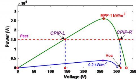
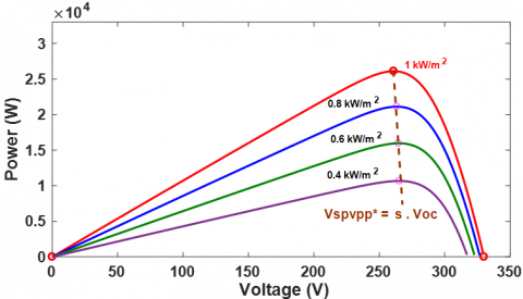
The CPI based on a P&O-CPI was implemented in SPVPP’s in the paper [20]. Even so, for the single-stage system the CPI is restricted to the right side of the MPP and has a demerit of less sturdiness of operating point around MPP for wide varying irradiance conditions. The operating point may go outside of the voltage limits greater than open circuit voltage (Voc) as shown in Figure 1. For single-stage SPVPP’s the operating point would be around the right side of the MPP, for low values of irradiance (G) = 0.2 kW/m2 the operating point constant power injection point-Right (CPIP-R) may go out of Voc as shown in Figure 1. To resolve the above-mentioned problems, a SPTS grid-connected SPVPP is used to expand working area of the system which should at the left of the MPP as CPIP-Left (CPIP-L) as shown in Figure 1. A reliable CPI action is always accomplished by controlling the SPVPP output power to the CPIP-L for rapid decrease in irradiance by adopting the P&O-CPI [21]. But the P&O-CPI algorithm is having a drawback of more oscillations for wide varying irradiance around MPP region when it is running in MPPT mode. For that reason, this paper proposes InC-CPI algorithm rather than P&O-CPI due to the high performance of InC algorithm for wide varying irradiance conditions during MPPT mode.
Figure 1. P-V curve showing the stability problems operating at CPIP-R
This article categorizes as: Section 2 presents the simple functioning of InC-CPI algorithm. Section 3 presents the simulation outcomes of the Inc-CPI algorithm for a two-stage system is presented. Section 4 concludes the article.
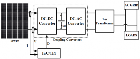
The basic SPTS grid tied SPVPP is shown in Figure 2, for SPTS system the working region is on the CPIP-L which decreases the voltage less than the Voc and it has to be increased to the dc-link voltage level by using the boost converter, this is not possible for single-stage systems where boost converter is absent in the system. The main focusing part of this paper is on the control algorithm of the DC-DC converter. When the SPVPP output power (PSPVPP) is below the set level (Pset), the PV device is to run in MPPT mode (PInC-MPPT). Once the output power approaches Pset it runs in the CPI mode, the SPVPP output power is held constant i.e., PSPVPP = Pset, which leads to a constant real power injection to the grid as given by Eq. (1) & Eq. (2).
${{P}_{SPVPP}}={{P}_{InC-MPPT}};whe{{n}_{{}}}{{P}_{SPVPP}}\le {{P}_{set}}$ (1)
${{P}_{SPVPP}}={{P}_{set}};whe{{n}_{{}}}{{P}_{SPVPP}}>{{P}_{set}}$ (2)
Figure 2. SPTS grid tied SPVPP
The inverter control is done by a cascaded regulator where the dc-link voltage is held constant by regulating the utility current, which is having an inside loop [22], and grid is supplied only with a real power which means that the SPVPP system works at a power factor of unity.
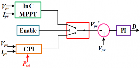
Figure 3. InC-CPI control strategy using PI controller
The functional blocks of the InC-CPI algorithm are shown in Figure 2. During MPPT mode, InC algorithm will operates and try to reach the MPP point with reduced power oscillations as compared with P&O algorithm. CPI mode will be initiated automatically when the operating power reaches Pset value. The proposed algorithm is flexible to operate at both sides of the MPP region but operating region below the MPP voltage is preferred to uphold the stability of the system. The control strategy of InC-CPI algorithm using PI controller for adjusting the voltage values is presented in Figure 3. The working voltage of SPVPP $V_{S P V P P}^{*}$ is given by the following equations as
$V_{SPVPP}^{*}={{V}_{InC-MPPT}};whe{{n}_{{}}}{{P}_{SPVPP}}\le {{P}_{set}}$ (3)
$V_{SPVPP}^{*}={{V}_{SPVPP,n}}-{{V}_{step}};whe{{n}_{{}}}{{P}_{SPVPP}}>{{P}_{set}}$ (4)
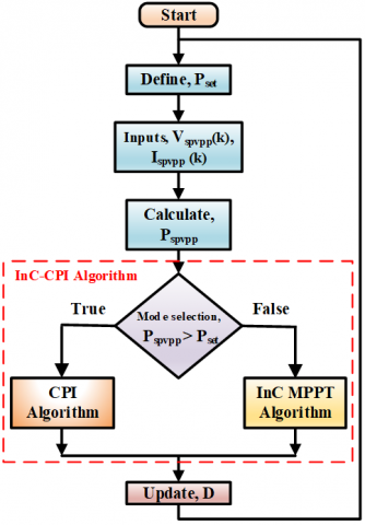
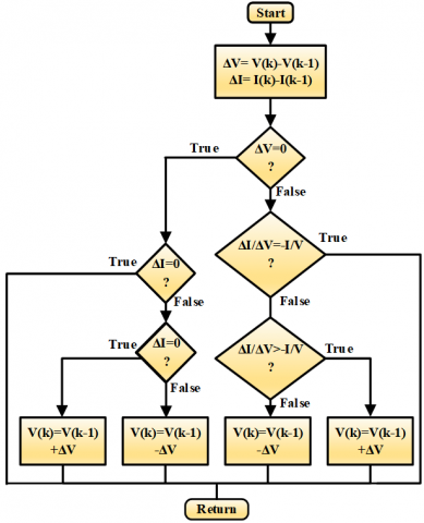
where, VINC-MPPT is the working voltage of InC MPPT algorithm and VSPVPP,n is the voltage of SPVPP system voltage and the Vstep is the step size used in the MPPT algorithm. The operational flow chart of the proposed Inc-CPI algorithm is given in Figure 4.
Figure 4. Operational Flowchart of InC-CPI
In Figure 4, the InC algorithm block is modified for the MPPT operation for grid tied SPVPP’s and is given in Figure 5.
Figure 5. Improved InC MPPT algorithm block for Grid tied SPVPP operation
The P&O-CPI is having the demerits of generating overshoots and increasing the power loss of the system under fast moving irradiance conditions in a clear and cloudy day. To overcome this draw backs of P&O-CPI, an InC-CPI is proposed in this system as InC algorithm inherently is having the less power oscillations as compared to P&O algorithm which will reduce the overshoots and leads to reduced power losses which will improve the performance of the system in fast moving irradiance conditions.
Another way to reduce the overshoots is by increasing the step size and the speed of tracking will be improved, this will be possible when there is fast decrease in irradiance. Initially huge step size is used and gradually the step size will be condensed as it is reaching the CPIP-L. The Power losses will be reduced by fixing a constant voltage output from the SPVPP in order to quickly improve the tacking speed when there is fast decrease in irradiance is noticed. For fast decrease in irradiance the voltage should be maintained approximately to 70% to 80% of the Voc as given Eq. (5) and shown in Figure 6.
$V_{SPVPP}^{*}=s.{{V}_{oc}};wher{{e}_{{}}}0.7\le s<0.8$ (5)
Figure 6. P-V curve showing the voltage of the SPVPP is almost maintained constant.
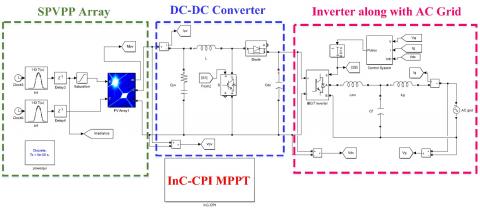
The simulation circuit of the proposed system is shown in Figure 7, which represents a SPTS grid tied SPVPP with all the and the simulations constraints are shown in Table 1 and Table 2.
Table 1. Simulation values of SPVPP grid tied system
|
S.No |
Parameter |
Values |
|
1 |
Inductance of Boost Converter |
1.8 mH |
|
2 |
DC link capacitance |
1100 µF |
|
3 |
Filter Inductance |
4.8 mH |
|
4 |
Grid Inductance |
4 mH |
|
5 |
Filter capacitance |
4.3 µF |
|
6 |
Inverter Switching Frequency |
8 kHz |
|
7 |
Boost converter switching Frequency |
16 kHz |
|
8 |
Grid voltage |
230 V |
|
9 |
DC-Link Voltage |
450 V |
|
10 |
Grid frequency |
50 Hz |
Table 2. BP solar BP365TS data sheet
|
S. No |
Electrical characteristics |
Ratings |
|
1 |
Maximum power (Pmax) |
65 W |
|
2 |
Voltage at Pmax (Vmp) |
8.7 V |
|
3 |
Current at Pmax (Imp) |
7.5 A |
|
4 |
Warranted minimum Pmax |
58.5 W |
|
5 |
Short-circuit current (Isc) |
8.1 A |
|
6 |
Open-circuit voltage (Voc) |
11 V |
|
7 |
Temperature coefficient of Isc |
(0.065 ± 0.015) %/℃ |
|
8 |
Temperature coefficient of Voc |
-(40 ± 10) mV/℃ |
|
9 |
Temperature coefficient of power |
-(0.5 ± 0.05) %/℃ |
|
10 |
NOCT (Air 20°C; Sun 0.8kW/m2; wind 1m/s) |
47 ± 2℃ |
|
11 |
Maximum series fuse rating |
15 A |
|
12 |
Maximum system voltage |
600 V |
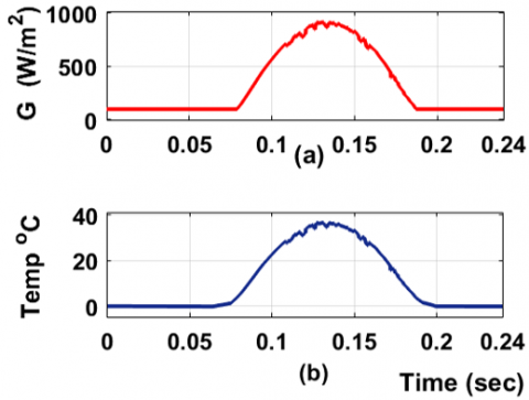
The input G and T values for simulating the proposed system is presented in the Figure 8, which represents the G and T values taken from minimum to maximum values within the STC for matching the real time environmental conditions which experienced by the SPVPP’s. The T and G values increases and decreases widely between the time (t) from 0.08 to 0.18 sec, and the values are close to STC around t equals to 0.13 to 0.16 sec as presented in Figure 8.
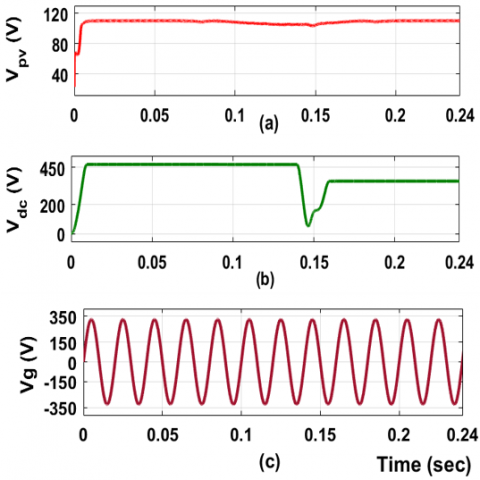
Figure 9. Measurements at Boost converter. (a) Input voltage, Vpv (b) Output voltage, Vdc. (c) Grid voltage (Vg)
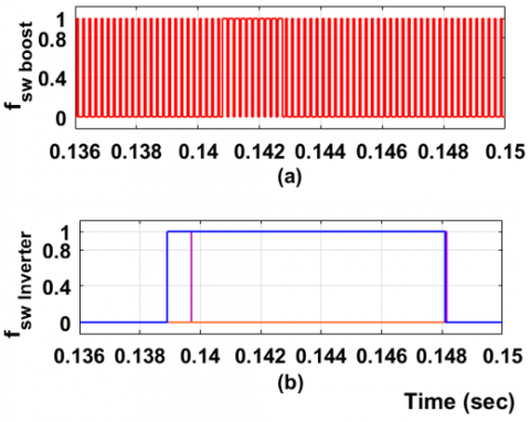
In Figure 9, the input and output measurements of the boost converter is presented, that the output DC voltage of the SPVPP (Vpv) is around 100 V. The input voltage of the boost converter boosts the voltage to 450 V which is the DC link voltage (Vdc) to meet the inverter requirements. The Grid voltage (Vg) is presented in Figure 9 (c), which illustrates that the Vg is sinusoidal. The boost converter and Inverter switching pulses are shown in Figure 10.
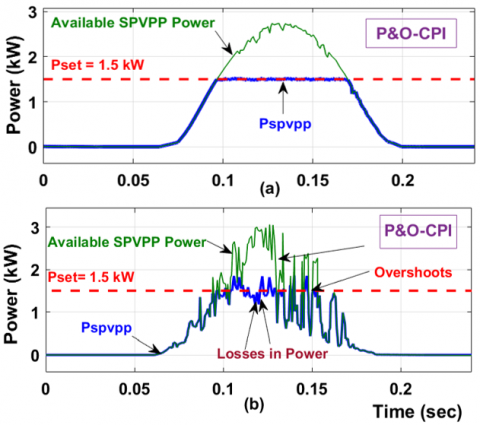
The performance results of the P&O-CPI algorithm is plotted by doing the simulations and shown in Figure 11. The system performance was evaluated by using two different irradiance conditions for a clear and cloudy day. Figure 11 (a) shows the results under a clear day having less irradiance changes during the day and observed that the Pspvpp is tracking the Pset value with less disturbance and Figure 11 (b) shows the results under a cloudy day that the Pspvpp is tracking the Pset but arises overshoots and power losses in the system as the P&O algorithm oscillates around the MPP that is Pset.
Figure 10. Boost converter switching pulses, (fsw boost) and Inverter switching pulses (fsw Inverter)
Figure 11. Simulation plots of P&O-CPI algorithm with two different environments. (a) clear day (b) cloudy day
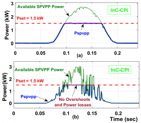
The performance results of the Proposed InC-CPI algorithm are plotted by doing the simulations and revealed in Figure 12 and Figure 12 (a) shows the results under a clear day having less irradiance changes during the day and observed that the Pspvpp is tracking the Pset value with less disturbance, like that of P&O-CPI algorithm. But Figure 12 (b) shows the results under a cloudy day that the Pspvpp is tracking the Pset with reduced overshoots and power losses when compared with the P&O-CPI algorithm.
Figure 12. Simulation plots of Proposed InC-CPI algorithm with two different environments. (a) clear day (b) cloudy day
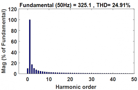
Figure 13. THD of Vg
In order to verify the performance of the proposed CPI-InC algorithm, it is compared with the commonly used algorithms like P&O and InC algorithms as presented in Table 3.
Table 3. Comparative analysis of MPPT algorithms
|
Parameter |
P&O |
InC |
CPI-InC |
|
Grid Stability issues |
More |
Moderate |
Less |
|
Power limiting capability |
No |
No |
Yes |
|
No of Iterations |
Moderate |
Less |
Less |
|
Speed of Convergence |
Varies |
Varies |
Moderate |
|
Sensors |
V&I |
V&I |
V&I |
|
Cost |
Less |
Less |
Moderate |
|
Hardware Complication |
Less |
Less |
Moderate |
|
Power Oscillations |
More |
Moderate |
Less |
|
Digital/Analog |
Both |
Digital |
Both |
|
Accuracy |
Less |
Moderate |
High |
|
Control Technique |
Sampling |
Sampling |
Sampling |
|
Dynamic tracking |
Sensible |
Moderate |
High |
|
Steady state tracking |
Sensible |
Moderate |
High |
|
Converter used |
DC/DC |
DC/DC |
DC/DC |
An InC-CPI algorithm for real power control of grid tied SPVPP’s is discussed in this article. The proposed InC-CPI algorithm will assure a constant real power injecting operation to the utility Grid within stable operating region. This algorithm mainly serves for two purposes, one is to limit the real power injected to the grid from the SPVPP’s as per the grid codes and regulations and the another one is to reduce the power oscillations around MPP. This algorithm overwhelms the major drawbacks of traditional P&O-CPI algorithm that the output power oscillations like overshoots and the power losses for fast moving irradiance are reduced considerably, thus by stable operation of the system is achieved. The results obtained clearly demonstrates that the oscillations are reduced for both clear day and cloudy days, there by improved the system efficiency when compared with the InC-CPI with the P&O-CPI around the duration of Pset value.
|
G |
Irradiance, W/m2 |
|
D |
Duty cycle |
|
T |
Temperature, ℃ |
|
s |
Constant lies between 0.7 to 0.8 |
|
Voc |
Open circuit voltage, volts |
|
Isc |
Short circuit current, Amps |
|
Vmp |
Maximum voltage, volts |
|
Imp |
Maximum current, Amps |
|
NOCT |
Nominal operating cell temperature |
[1] Kotla, R.W., Yarlagadda, S.R. (2020). Mathematical modelling of SPV array by considering the parasitic effects. SN Applied Sciences, 2(1): 50. https://doi.org/10.1007/s42452-019-1861-x
[2] Hussein, K.H., Muta, I., Hoshino, T., Osakada, M. (1995). Maximum photovoltaic power tracking: an algorithm for rapidly changing atmospheric conditions. IEEE Proceedings on Generation, Transmission and Distribution, 142(1): 59-64. https://doi.org/10.1049/ip-gtd:19951577
[3] Amin, S., Khan, S., Qayoom, A. (2018). Comparative analysis about the study of maximum power point tracking algorithms: A review. 2018 International Conference on Computing, Mathematics and Engineering Technologies (iCoMET), Sukkur, Pakistan, pp. 1-8. https://doi.org/10.1109/ICOMET.2018.8346451
[4] Wilson, K.R., Rao, Y.S. (2019). Comparative analysis of MPPTT algorithms for PV grid tied systems: A review. In 2nd IEEE International Conference on Intelligent Computing, Instrumentation and Control Technologies (ICICICT), 1: 1105-1110. https://doi.org/10.1109/ICICICT46008.2019.8993148
[5] Ahmad, A.R., Smadi, I.A. (2019). Partial shading detection and global MPPT algorithm for PV system. In IEEE Jordan International Joint Conference on Electrical Engineering and Information Technology (JEEIT), Amman, Jordan, Jordan, pp. 135-140.
[6] Wilson, K.R., Rao Y.S. (2019). Effects of partial shading on different structures of solar photovoltaic arrays. Journal of Mechanics of Continua and Mathathematical Sciences, 14(6): 845-854. https://doi.org/10.26782/jmcms.2019.12.00062
[7] Stetz, T., Marten, F., Braun, M. (2012). Improved low voltage grid-integration of photovoltaic systems in Germany. IEEE Transactions on Sustainable Energy, 4(2): 534-542. https://doi.org/10.1109/TSTE.2012.2198925
[8] Ahmed, A., Ran, L., Moon, S., Park, J.H. (2013). A fast PV power tracking control algorithm with reduced power mode. IEEE Transactions on Energy Conversion, 28(3): 565-575. https://doi.org/10.1109/TEC.2013.2266343
[9] Yang, Y., Wang, H., Blaabjerg, F., Kerekes, T. (2014). A hybrid power control concept for PV inverters with reduced thermal loading. IEEE Transactions on Power Electronics, 29(12): 6271-6275. https://doi.org/10.1109/TPEL.2014.2332754
[10] Maxwell, D. (2013). Parts of Northern Ireland’s Electricity Grid Overloaded. BBC News. [Online]. http://www.bbc.co.uk/.
[11] Esram, T., Chapman, P.L. (2007). Comparison of photovoltaic array maximum power point tracking techniques. IEEE Transactions on Energy Conversion, 22(2): 439-449. https://doi.org/10.1109/TEC.2006.874230
[12] Wang, H., Liserre, M., Blaabjerg, F., Rimmen, P., Jacobsen, J.B., Kvisgaard, T., Landkildehus, J. (2013). Transitioning to physics-of-failure as a reliability driver in power electronics. IEEE Journal of Emerging and Selected Topics in Power Electronics, 2(1): 97-114. https://doi.org/10.1109/JESTPE.2013.2290282
[13] Energinet, D. (2010). Technical regulation 3.2.5 for wind power plants with a power output greater than 11 kW. Available on. Energinet.dk, Errits, Denmark, Document No.: 55986/10, Tech. Rep.
[14] Modi, N.D. (2020). Pm’s bid for a blackout could trip power grids. Business Insider India, [Online]. Available: https://www.businessinsider.in/india/news/modis-bid-for-a-blackout-could-trip-power-grids-heres-what-happened-the-last-two-times-india-had-a-massive-power-outage/articleshow/74981355.cms.
[15] Rosenwirth, D., Strubbe, K. (2013). Integrating Variable Renewables as Germany Expands Its Grid. RenewableEnergyWorld.com.
[16] Gaztanaga, H., Landaluze, J., Etxeberria, O.I., Padros, A., Berazaluce, I., Cuesta, D. (2013). Enhanced experimental PV plant grid-integration with a MW lithium-ion energy storage system. In IEEE Energy Conversion Congress and Exposition, Denver, CO, USA, pp. 1324-1329. https://doi.org/10.1109/ECCE.2013.6646858
[17] Fraunhofer, I.S.E. (2014). Recent facts about photovoltaics in Germany. Fraunhofer Inst. Sol. Energy Syst., Freiburg, Germany, Tech. Rep., [Online]. http://www.pv-fakten.de/.
[18] Tonkoski, R., Lopes, L.A., El, F.T.H. (2010). Coordinated active power curtailment of grid connected PV inverters for overvoltage prevention. IEEE Transactions on Sustainable Energy, 2(2): 139-147. https://doi.org/10.1109/TSTE.2010.2098483
[19] Ueda, Y., Kurokawa, K., Tanabe, T., Kitamura, K., Sugihara, H. (2008). Analysis results of output power loss due to the grid voltage rise in grid-connected photovoltaic power generation systems. IEEE Transactions on Industrial Electronics, 55(7): 2744-2751. https://doi.org/10.1109/TIE.2008.924447
[20] Wandhare, R.G., Agarwal, V. (2014). Precise active and reactive power control of the pv-dgs integrated with weak grid to increase pv penetration. In IEEE 40th Photovoltaic Specialist Conference (PVSC), Denver, CO, USA, pp. 3150-3155. https://doi.org/10.1109/PVSC.2014.6925604
[21] Kjaer, S.B., Pedersen, J.K., Blaabjerg, F. (2005). A review of single-phase grid-connected inverters for photovoltaic modules. IEEE Transactions on Industry Applications, 41(5): 1292-1306. https://doi.org/10.1109/TIA.2005.853371
[22] Blaabjerg, F., Teodorescu, R., Liserre, M., Timbus, A.V. (2006). Overview of control and grid synchronization for distributed power generation systems. IEEE Transactions on Industrial Electronics, 53(5): 1398-1409. https://doi.org/10.1109/TIE.2006.881997