Raghavaiah Katuri* | Srinivasarao Gorantla
OPEN ACCESS
Hybrid Energy Storage System (HESS) with battery and ultra-capacitor (UC) gives good results for Hybrid Electric Vehicle (HEV)/Electric Vehicle (EV) application due to its inherent high energy and high power densities. High power capability of UC can be utilized during cold starting and sudden requirement of the EV. Normal power need can be supplied by the battery itself only. The main obstacle with HESS based EVs is the transition between battery and UC. The smooth transition plays a key role in improving battery life. The main aim of this work is to develop a control technique for automatic switching between energy sources corresponding to the speed of the motor. In the proposed control action, motor speed plays a major role in switch the energy sources in HESS. To attain the objective, another controller has been designed with four math functions corresponding to the speed of the motor termed as Math Function Based (MFB) controller. Thereafter the designed MFB controller combined with a conventional PI controller applied to the entire circuit at different load conditions. In the same way, MFB with PID controller also applied to the circuit. Finally, comparative analysis has been done between two hybrid controllers. The MATLAB/Simulink results of MFB with PI and MFB with PID has been attained and also compared, discussed.
HESS, hybrid electric vehicle, electric vehicle, battery, ultra-capacitor, uni-directional converter, bi-directional converter, MFB controller, proportional Integral (PI) controller, proportional integral derivative (PID) controller
Conventional transportation system with the IC engine is ready to replace with Electric vehicles. Though IC engine based vehicle has their own advantages they are bagged with some drawbacks, on the other hand, major cons with the IC engine based vehicles is noise as well as air pollution. Because during successive operation of vehicle it produces some harmful gases, which will affect the atmosphere, the second one is the fuel cost because petrol/ diesel is not abundantly available in nature, after some decades it may disappear. To overcome such cons from conventional vehicles, electric vehicles have been introduced with the battery as a source to propel the vehicle. With the electric vehicle, some problems like pollution, usage of petrol is completely avoided. But the main problem in this is driving range and also battery size for peak power requirements. This will take the extra weight to the vehicle and increases the cost of the vehicle, reduces the driving range reliability. HESS has been introduced by combining battery with UC. The combination battery, UC meets the normal power as well as peak power requirement. But the major obstacle with HESS is controlling of energy sources depending on the electric vehicle requirement. In order to overcome that may controllers have been designed for smooth switching of energy sources in HESS [1].
For proper energy sharing a rate limit function-based energy management technique is proposed. With the help of the proposed controller correct sharing of energy between two sources happens which will enhance the main source of life. The base source is capable of supply the steady state power to the load on the other hand sudden required power is meet by the supporting source [2-3]. During high power density requirement, energy storage is the main issue from electric vehicles for its successful operation. Provided battery must be low cost, having a long life cycle and small in size. But batteries having low power density, and fortunately, UCs are available with high power density. So, batteries lagged power can be supplied by the UC during peak load time of the EV. Energy control can be achieved from DC-DC converters by providing proper pulses to the switches based on the state of charge of battery and UC with the help of PI controller [4]. A fuzzy logic supervisory wavelet-transform frequency decoupling-based energy management strategy has been proposed to powertrain to propel the two different power rating machines having HESS with battery and ultra-capacitor. The adopted method guarantees the rated power from battery and transient power from the ultra-capacitor, power splitting between sources can be done based on the torque requirement [5]. Fuzzy logic-based HESS has been designed to reduce the power rating of the BDC by meeting the power requirement of the DC bus. Total four Fuzzy logic controller has been designed for different modes of operation of electric vehicle which depending upon the speed of the electric vehicle. Designed Fuzzy logic calculates the power requirement between the battery and ultra-capacitor [6]. Bidirectional converter plays a key role during switching of battery and UC as per the electric vehicle requirement depending on the road conditions. Several soft technique schemes are adopted, compared all switching methods and suggested the best one for practical implementation [7]. Energy management can be done based on DC bus voltage control as well as current control. Energy sharing held between the Fuel cell and UC. The energy management control strategies have been implemented in an electric vehicle for smooth switching between energy sources [8]. The newly designed DC-DC bidirectional converter acts as a bridge in between main energy source and auxiliary source in HESS. Depending upon the load on the electric vehicle the high and low voltages appear across the terminals of the bidirectional converter [9]. The modern world needs electric vehicle technology. Generally bidirectional and unidirectional converters are used to the controller the energy sources of the electric vehicle depending upon the vehicle dynamics. Conventionally PWM technique is used to generate the pulses to switches in converters PI and PID controller are used to generating pulse signals and compared these there, suggested the good technique [10]. Adaptive sliding mode with hysteresis control strategy can be used to supply the power to the EV in all dynamics. Boost converter action requires during peak power need of an electric vehicle, at this particular instant UC will supply the required power to the electric vehicle [11].
This section deals with considerations which are the development of Battery/UC discussed in detail. The basic design considered in the HESS topologies is discussed in detail.
2.1 Battery
Figure 1. Battery model representation
• The source VOCV tells about open circuited value, and this is directly proportional to SOC of the battery.
•The voltage drop in the terminal of the circuit can be modeled from the resistor $R_Ω$ and this resistance is directly related to the SOC of the battery.
• The voltage drop due to $R_{dll} C_{dll}$ and $R_{dif} C_{dif}$ models simulate the polarization progression of the battery.
The voltage across the battery at terminals is given below
$V_{bat}=V_{OCV}+V_{RΩ}+V_{RC}$ (1)
State of charge of the battery is given by
$SOC=100.(SOC_{int}-\frac{1}{Q_n} ∫ηI_b dt)$ (2)
The voltage across the internal resistance of the battery is
$V_{RΩ}=I_b\frac{x_{14}}{\sqrt{SOC+X_{15}\bullet SOC.sign(I_b)}}$ (3)
2.2 Ultra-capacitor model
The voltage state of Ultra-Capacitor for RC is given by
$V(t)=V_iexp(-\frac{t}{RC})$ (4)
Here RC represents time constant value
Ultra-capacitor bank energy required can find from
$E_{UC}=\frac{1}(2) C(V_i^2-V_f^2 )$ (5)
Figure 2. General circuit for UC model
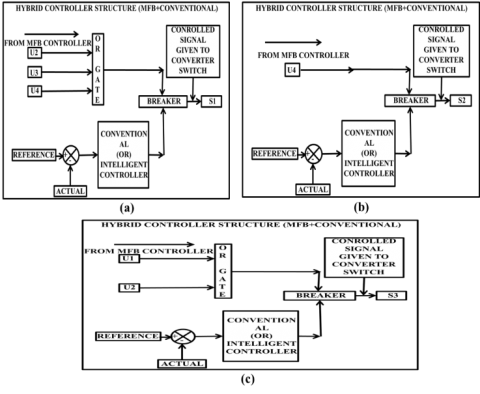
The main block diagram mainly representing with hybridizing different controllers by means of a circuit breaker to produce the required switching signal to specific switch present in the bidirectional converter (BDC) and unidirectional converter (UDC). Generally, the base source is associated near to the UDC end, on the other hand, BDC is associated at supporting source UC end. Here the conventional controller is used to produce the switching signal whereas the MFB controller is used to regulate the signal corresponding to the vehicle dynamics.
Figure 3. Block diagram representation with the proposed control technique
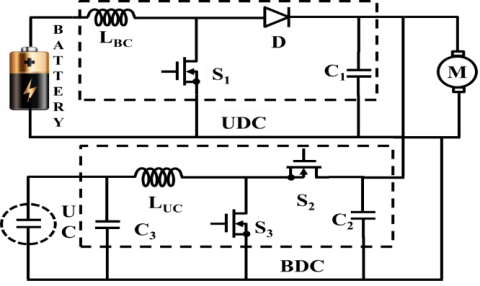
Figure 4. Circuit with main converters
Circuit with main converters is representing with Figure 4 which mainly consisting of three switches S1, S2, and S3. Among the three switches S2, S3 belong the BDC, another switch S1 is related to UDC. Here BDC is capable of operating under boost as well as buck modes. According to the proposed work model, the UDC is always in ON condition except during a heavy load condition. The switch S2 is only in ON condition during the free running of the motor.
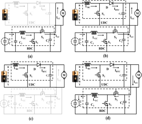
The main circuit with hybrid controller action can be done in four modes which are required to know the performance of the vehicle during different load conditions. Figure 5(a) is related to a heavy load applied to the motor due which the switch S3 is in ON condition related to the BDC and no regulated pulses are provided to the UDC. Figure 5(b) corresponds to the slightly more than rated load on the motor, due to which UC and battery together supply the power the motor which starts the operation of BDC and UDC (boost), in this mode the switches S1, S3 both are in ON state. Figure 5 (c) circuit corresponding to the rated load on the motor, during this period the main source itself supply power to the load and switch S1 only in ON condition, no regulated signals generated to BDC. The circuit in figure 5 (d) is corresponding to the no load applied to the motor which starts the operation of BDC (buck) as well as UDC (boost) and the switches S1 and S2 both are in ON condition.
Figure 5. (a) Circuit with main converters in mode-I, (b) Circuit with main converters in mode-II, (c) Circuit with main converters in mode-III, (d) Circuit with main converters in mode-IV
The considered MFB controller has integrated with PI as well as PID controller for a smooth transition of two sources. The two-hybrid controller has been implemented, in which MFB plays a key role by measuring the speed of the motor and PI or PID is able to generate the error signal by comparing the actual and reference voltage values of converter BDC and UDC. Finally, both the controller of MFB with PI or MFB with PID works together and generates the pulses to the switches corresponding to the dynamics of the vehicle.
5.1 Implementation of control strategy with MFB controller
The designed MFB controller working is mainly based on the speed of the motor. Here the main circuit is realized into four modes depending upon the load applied.
(a) In the first mode of operation the speed of considered the speed of the motor is ≤ 4800 rpm due to a huge load due to which the math function U1 generates the signal as 1 and other three math functions U2, U3, U4 produces a signal as 0.
(b) During mode two operation the speed of the motor maintains between 4600 rpm to 4800 rpm due to more than rated load. Due to which the MFB controller produces a signal as 1 for U1, U2 and produces 0 for other two math functions.
(c) In the third mode, the speed motor maintains between 4801 rpm to 4930 rpm due to rated load which initiates the MFB operation as producing a signal as 1 for U3 and produces a signal as 0 for other math functions.
(d) In the fourth mode of operation, the speed of the motor is ≥4931 rpm due to no load applied due to which the math function U4 generates the signal as 1 and other three math functions U1, U2, U3 produces a signal as 0.
Figure 6. Developed control technique represented with the flowchart
5.2 Generation of pulse signals to UDC and BDC
Controlled switching pulses to S1: If MFB produces U2 or U3 or U4 then the switching pulses produced by the PI/PID are given to switch S1 which starts the operation of UDC working under boost mode.
Controlled switching pulses to S2: If MFB produces only
U4 then the switching pulses produced by the PI/PID are given to switch S2 which starts the operation of BDC working under buck mode.
Controlled switching pulses to S3: If MFB produces U1 or U2 then the controlled pulses produced by the PI/PID are given to switch S3 which starts the operation of BDC working under boost mode.
Figure 7. (a) Pulse signal generating structure for S1 (b) Pulse signal generating structure for S2 (c) Pulse signal generating
6.1 Mode-I operation results
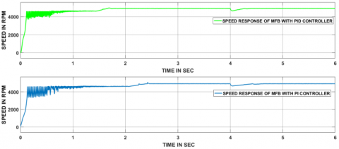
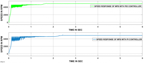
Figure 8. The speed responses of the vehicle corresponding to a heavy load condition
In this case, a heavy load applied to the motor. Speed responses of PID and PI have shown in Figure 8. The speed of the motor reached steady-state value before 2 sec with PID controller whereas with PI controller speed reached steady state value between 2 to 3 sec. Thereafter load is applied to the motor at 4 sec related to that speed also changed drastically and the motor speed doesn’t attain the steady state in a given time.
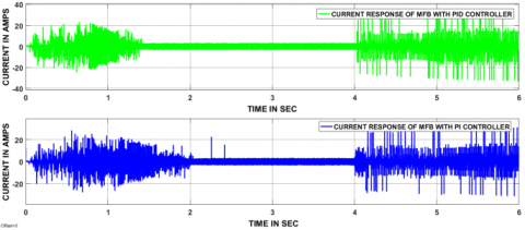
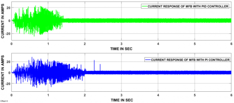
Figure 9. The current responses of the vehicle
At starting MFB with PID controller has taken less than 2 sec to reach the steady-state value whereas MFB with PI controller has taken more than 2 sec to reach a steady-state value. Before reaching the steady state value the motor is in the transient period that is the reason why huge current variations are present during the transient period. After reaching steady state value two controllers’ current waveforms showing the normal current only. At 4 sec load applied to the motor, this leads to present the huge current variations.
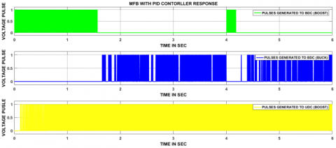
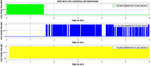
Figure 10. The controlled switching signals to BDC and UDC by MFB with PID controller
Pulse signals have been produced to BDC and UDC during heavy load condition, above Figure 10 shows MFB with PID controller. At starting of the motor required huge power that can supply by the UC only so pulses have been produced to only BDC (boost). After that, battery and UC together provide power, that means during the period 0.1sec to 1.5 sec pulses have been produced to BDC (boost mode) as well as UDC. During the period 1.5 to 4 sec motor is in steady state condition, so pulses have been produced to UDC and BDC (buck mode). At 4 sec load applied on the motor, due to which motor reduces correspondingly current value increases and pulses have been produced to BDC (boost mode) before motor reaching the steady state.
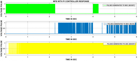
Figure 11. The controlled switching signals to BDC and UDC by MFB with PI controller
At starting of the motor required huge power that can supply by the UC only so pulses have been produced to only BDC (boost). After some time, battery and UC collectively give power, that means during the period 0.1sec to 2.2 sec pulses have been produced to BDC (boost mode) and UDC. During the period 2.2 to 4 sec motor is in steady state condition, so pulses have been produced to UDC and BDC (buck mode). At 4 sec load applied on the motor, the speed of the motor reduces correspondingly current value increases and pulses have been produced to only BDC (boost mode) before motor reaching the steady state.
6.2 Mode-II operation results
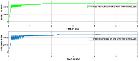
Figure 12. The speed responses of the vehicle corresponding to slightly more than the rated load
The speed of the motor reached steady-state value before 2 sec with PID controller whereas with PI controller speed reached steady state value between 2 to 3 sec. The load has been applied to the motor at 4 sec and speed also changed drastically according to load. The MFB with PID has taken 0.2 sec and MFB with PI has taken 0.4 sec to reach a stable state.
Figure 13. The current responses of the vehicle
MFB with PID controller has taken less than 2 sec to reach the steady-state value whereas MFB with PI controller has taken more than 2 sec to reach a steady-state value. Before reaching the steady state value the motor is in the transient period that is the reason why huge current variations are present during the transient period. After reaching steady state value two controllers’ current waveforms showing the normal current only. At 4 sec slightly more than the rated load applied on the motor, this leads to present current variations.
Figure 14. The controlled switching signals to BDC and UDC by MFB with PID controller
At 4 sec load applied on the motor, the speed of the motor reduces correspondingly current value increases and pulses have been produced to only BDC (boost mode), thereafter motor reached the steady state with 0.2 sec by MFB with PID action.
Figure 15. The controlled switching signals to BDC and UDC by MFB with PI controller
At 4 sec load applied on the motor, the speed of the motor reduces correspondingly current value increases and pulses have been produced to only BDC (boost mode), thereafter motor reached the steady state with 0.4 sec by MFB with PI action.
6.3 Mode-III operation results
Figure 16. The speed responses of the vehicle during a rated load
Speed responses of PID and PI showed in figure 16. The speed of the electric motor reached steady-state value before 2 sec with PID controller whereas with PI controller speed reached steady state value between 2 to 3 sec. The load has been applied to the motor at 4 sec and speed also decreased according to load. After that, the motor has taken 0.1 sec and 0.3 sec to reach a stable state by the MFB with PID, MFB with PI action.
Figure 17. The current responses of the vehicle
Before reaching the steady state value the motor is in the transient period that is the reason why huge current variations are present during the transient period. After reaching steady state value two controllers’ current waveforms showing the normal current only. At 4 sec rated load applied on the motor. Due to this, the speed of the motor decreases slightly and that will increase the current value.
Figure 18. The controlled switching signals to BDC and UDC by MFB with PID controller
At 4 sec load applied on the motor, the speed of the motor reduces correspondingly current value increases and pulses have been produced to only BDC (boost mode). Thereafter motor took 0.1 sec to reach the stable state by the designed controller MFB with PID action.
Figure 19. The controlled switching signals to BDC and UDC by MFB with PI controller
At 4 sec load applied on the motor, the speed of the motor reduces correspondingly current value increases and pulses have been produced to only BDC (boost mode). Thereafter motor took 0.3 sec to reach the stable state by the designed controller MFB with PI action.
6.4 Mode-IV operation results
Figure 20. The speed responses of the vehicle corresponding to no load condition
During this mode, no load is applied to the motor. Speed responses of MFB with PID and MFB with PI shown in figure 20. The speed of the motor reached the steady-state value in 1.5 sec by MFB with PID controller whereas MFB with PI controller speed reached steady state value in 2.2 sec.
Figure 21. The current responses of the vehicle
MFB with PID controller has taken 1.5 sec to reach the steady-state value whereas MFB with PI controller has taken 2.2 sec to reach a steady-state value. Before reaching the steady state value the motor is in the transient period that is the reason why huge current variations are present during the transient period. After reaching steady state value two controllers’ current waveforms showing the normal current only.
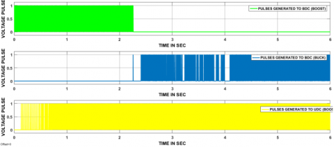
Figure 22. The controlled switching signals to BDC and UDC by MFB with PID controller
Pulse signals have been generated to BDC as well as UDC during heavy load condition above figure 22 represents to MFB with PID controller. At starting of the motor required huge power that can supply by the UC only so pulses have been generated to only BDC, which works in boost mode. After some time, battery and UC together supplies power, that means during the period 0.1sec to 1.5 sec pulses have been generated to BDC (boost mode) as well as UDC. During the period 1.5 to 6 sec motor is in steady state condition, so pulses have been generated to UDC as well as BDC (buck mode).
Figure 23. The controlled switching signals to BDC and UDC by MFB with PI controller
Table 1. Representation of power flow direction corresponding to the applied load
|
S.No |
Mode type |
UDC state |
BDC state |
Power flow direction |
|
1 |
Mode-I |
Off |
Boost |
UC $\to$load |
|
2 |
Mode-II |
Boost |
Boost |
Battery +UC $\to$ load |
|
3 |
Mode-III |
Boost |
Off |
Battery $\to$ load |
|
4 |
Mode-IV |
Boost |
Buck |
Batter $\to$ UC+load |
At starting of the motor required huge power that can supply by the UC only so pulses have been produced to only BDC (boost). After some time, battery and UC collectively give power, that means during the period 0.1sec to 2.2 sec pulses have been produced to BDC (boost mode) and UDC. During the period 2.2 to 6 sec motor is in steady state condition, so pulses are produced to UDC and BDC (buck mode).
HESS with battery and UC serves better for HEV/EV application. The designed MFB controller has united with the PI controller and the PID controller made it as a hybrid controller. Both the hybrid controller has been generated switching signals to the switches in BDC and UDC depending upon the speed of the electric motor. The simulation results of MFB with PI and MFB with PID have compared by taking speed curve as a reference with their delay time, rise time, peak time, settling time and maximum peak overshoot. From all the comparative study the two controllers are given satisfactory results except settling time at huge load condition on the motor. Finally, the designed hybrid controller MFB plus PID is given better results for a smooth transition of energy sources during all modes of operation, because it has taken 1.5 sec to reach the steady state before applying the load on the motor. After load applying on the motor MFB with PI taken 0.3 sec whereas PID with MFB has taken only 0.1sec to reach steady state. All comparative results have been done and tabulated in the conclusion section.
Table 2. Comparative study of controllers corresponding to time domain specifications
|
Constraint |
MFB with PI |
MFB with PID |
|
Delay time (sec) |
0.15 |
0.1 |
|
Rise time (sec) |
2.1 |
1.3 |
|
Peak time (sec) |
2.3 |
1.7 |
|
Settling time (sec) |
2.5 |
1.9 |
|
Maximum peak overshoot (%) |
3 |
2 |
Table 3. Comparative study during starting and loaded condition
|
Controller |
Steady-state time at load applied (sec) |
Steady-state time at starting (sec) |
|
MFB with PI |
0.3 |
2.2 |
|
MFB with PID |
0.1 |
1.5 |
[1] Shen J, Khaligh A. (2016). Design and real-time controller implementation for a battery-ultracapacitor hybrid energy storage system. IEEE Transactions on Industrial Informatics 12(5): 1910-1918. https://doi.org/10.1109/TII.2016.2575798
[2] Wu D, Todd R, Forsyth AJ. (2015). Adaptive rate-limit control for energy storage systems. IEEE Transactions on Industrial Electronics 62(7): 4231-4240. https://doi.org/10.1109/TIE.2014.2385043
[3] Xiang C, Wang Y, Hu S, Wang W. (2014). A new topology and control strategy for a hybrid battery-ultracapacitor energy storage system. Energies 7(5): 2874-2896. https://doi.org/10.3390/en7052874
[4] Allègre AL, Bouscayrol A, Trigui R. (2013). Flexible real-time control of a hybrid energy storage system for electric vehicles. IET Electrical Systems in Transportation 3(3): 79-85. https://doi.org/10.1049/iet-est.2012.0051
[5] Yin H, Zhou W, Li M, Ma C, Zhao C. (2016). An adaptive fuzzy logic-based energy management strategy on battery/ultracapacitor hybrid electric vehicles. IEEE Transactions on Transportation Electrification 2(3): 300-311. https://doi.org/10.1109/TTE.2016.2552721
[6] Dusmez S, Khaligh A. (2014). A supervisory power-splitting approach for a new ultracapacitor–battery vehicle deploying two propulsion machines. IEEE Transactions on Industrial Informatics 10(3): 1960-1971. https://doi.org/10.1109/TII.2014.2299237
[7] Zhang Y, Cheng XF, Yin C, Cheng S. (2018). A Soft-switching bidirectional DC-DC converter for the battery super-capacitor hybrid energy storage system. IEEE Transactions on Industrial Electronics. https://doi.org/10.1109/ECC.2015.7330988
[8] Oukkacha I, Camara MB, Dakyo B, Parade JY. (2017). Onboard energy management for electric vehicles applications—using fuel cell and ultracapacitors. In Industrial Electronics Society, IECON 2017-43rd Annual Conference of the IEEE, pp. 5099-5104. https://doi.org/10.1109/IECON.2017.8216881
[9] Lai CM, Cheng YH, Hsieh MH, Lin YC. (2018). Development of a bidirectional DC/DC converter with dual-battery energy storage for hybrid electric vehicle system. IEEE Transactions on Vehicular Technology 67(2): 1036-1052. https://doi.org/10.1109/TVT.2017.2763157
[10] Das R, Uddin Chowdhury MA. (2016). PI controlled Bi-directional DC-DC converter (BDDDC) and highly efficient boost converter for electric vehicles. In 2016 3rd International Conference on Electrical Engineering and Information Communication Technology (ICEEICT), pp. 1-5. https://doi.org/10.1109/CEEICT.2016.7873094
[11] Wang B, Xu J, Wai RJ, Cao B. (2017). Adaptive sliding-mode with hysteresis control strategy for simple multimode hybrid energy storage system in electric vehicles. IEEE Transactions on Industrial Electronics 64(2): 1404-1414. https://doi.org/10.1109/TIE.2016.2618778