Mohamed Jarjar* | Said Hraoui | Said Najah | Khalid Zenkouar
© 2021 IIETA. This article is published by IIETA and is licensed under the CC BY 4.0 license (http://creativecommons.org/licenses/by/4.0/).
OPEN ACCESS
This document traces the development of a new cryptosystem using two circuits ensured by a deep Vigenere classical technique improvement. This new technique employs several dynamic substitutions matrices attached to chaotic replacement functions; whose construction will be detailed. The first round will start by modifying the seed pixels based on the initial values calculated from the original image, and will be infected through the chaotic map used to overcome the uniform image problem, followed by the injection of Vigenere technology improvements. The output vector will be subdivided into three sized blocks for future application of deeply improved genetic mutations to better adapt to medicine and color image encryption. The second round will increase the complexity of the attack and improve the installed systems. Simulations performed on a large number of images of different sizes and formats ensure that our approach is not exposed to known attacks.
Vigenere grid, chaotic map, encryption function, S-Box, genetic mutation
The rapid development of chaos theory in mathematics provides researchers with opportunities to further improve some classic encryption systems. In front of this great security focus, many techniques for color image encryption have flooded the digital world, mostly exploiting number theory and chaos [1, 2]. Others are attempting to update their policies by improving some classical techniques, such as Hill [3, 4], Cesar, Vignere [5, 6], Feistel [7, 8].
1.1 Vigenere's classical technique
This technology is based on static (V) matrix defined by the following algorithm. Despite the knowledge of the substitution matrix, this method has been able to withstand more than three centuries.
|
Algorithm 1. Classical Vigenere |
|
$\left\{\begin{array}{c}\text { Fist Row } \\ \text { For } i=1 \text { to } 26 \\ V(1, i)=i \\ \text { Next } i \\ \text { folloying Rows } \\ \text { For } i=2 \text { to } 26 \\ \text { For } j=1 \text { to } 26 \\ V(i, j)=V(i-1,(j+1), 26) \\ \text { Next } j, i\end{array}\right.$ |
Let $(P)$ : plain text, $(C)$ : cypher text; $(K)$ : Encryption key, $(V)$ Vigenere matrix and $(l)$ : length of clear text. So
$\begin{cases}C_{i}=V\left(P_{i}, K_{i}\right)=\left(P_{i}+K_{i}\right) & \bmod 26 \\ P_{i}=V\left(C_{i}, K_{i}\right)=\left(P_{i}-K_{i}\right) & \bmod 26\end{cases}$ (1)
Even though Vigenere's matrix was known, the encryption was able to withstand several centuries. But, Babagh's cryptanalysis is not efficient in not knowing the size of the encryption key. Several attempts to improve Vigenere's technique have invaded the digital world we quote [9, 10]. In this work, the new structure of the substitution matrix and its attached replacement function will be described in detail.
1.2 Problematic
In the conventional Vigenere system, the recognition problem of the private size key, exposes the algorithm to statistical attacks. discovered and detailed by Babagh. The knowledge of the substitution matrix is an opportunity to expose the conventional system to brute force attacks. Moreover, in the absence of the broadcast operation and the chaining facility, all classical systems remain exposed to differential attacks. In addition, block ciphering independently facilitates the implementation of dictionary and statistical attacks.
1.3 Our contribution
Our contribution is to improve the encryption structure and function for replace the substitution matrix. To this end, two improved encryption functions will be constructed and two S-Boxes will be generated in different ways from the two most widely used chaotic graphs in the world of cryptography [11, 12]. In addition, the principle of double encryption will be applied to all pixels of the original image, and a chaotic broadcast will be installed in each tower, which will increase the impact of the avalanche effect and protect the system from differential attacks. Contrary to the classic method, our system will use different S-Boxes for decoding, and different encryption functions will be used.
Article Highlights
This new algorithm offers two tricks ensured by a deep improvement of Vigenere. We mention the most important changes made.
Based on chaos [13, 14], this new technology which acts at the pixel level by two Vigenere rotations provided by a large dynamic substitution’s matrices and replacement functions [15-17], is based on many steps
Step 1: Chaotic Sequences Development
In order to build a new symmetric encryption algorithm using a large secret key, we will set up three chaotic sequences most used in the field of cryptography. Such a choice is due to the simplicity of their elaboration and integration in the encryption system, as well as to their great sensitivity to the initial parameters.
2.1 The logistics map
The logistic map (un) [18, 19] is a recurrent sequence described by a simple polynomial of second degree defined by the following equation
$\left.u_{0} \in\right] 0,51[, \mu \in[3,75 \quad 4]$
$u_{n+1}=\mu u_{n}\left(1-u_{n}\right)$ (2)
This logistic card is widely used in the field of cryptography. This is due to its simplicity and its high sensitivity to initial conditions
2.2 Piecewise Linear Chaotic Map (PWLCM)
It is a real linear (wn) sequence [20] by pieces defined by the equation below
$\left\{w_{n}=f\left(w_{n-1}\right)\right.$
$=\left\{\begin{array}{cc}\frac{w_{n-1}}{d} & \text { if } 0 \leq w_{n-1} \leq d \\ \frac{w_{n-1}-d}{0.5-d} & \text { if } d \leq w_{n-1} \leq 0.5 \\ \text { Else } & f\left(1-w_{n-1}\right)\end{array}\right.$ (3)
2.3 The Skew Tent Map (SKTM)
The Skew tent [21] map (vn) will be redefined as the next equation
$\left\{\begin{array}{l}\left.\mathrm{v}_{0} \in\right] 01[\mathrm{p} \in] 0,51[ \\ \mathrm{v}_{\mathrm{n}+1}=\left\{\begin{array}{l}\frac{\mathrm{v}_{\mathrm{n}}}{\mathrm{p}} \text { if } 0 \prec \mathrm{v}_{\mathrm{n}}<\mathrm{p} \\ \frac{1-\mathrm{v}_{\mathrm{n}}}{1-\mathrm{p}} \text { if } \mathrm{p} \prec \mathrm{v}_{\mathrm{n}<1}\end{array}\right.\end{array}\right.$ (4)
Step 2: Chaotic used Vector designThe combination of these three chaotic maps will be used to generate all the sub keys necessary for the proper functioning and operation of our new technology.
Our work requires the construction of three chaotic vectors (CL), (KL) and (ML), with a coefficient of (G256), and (CR), (RC) and (BC) are three binary vectors regarded as the control vector. We use the Xor operator defined by the following table.
|
$\oplus$ |
0 |
1 |
|
0 |
0 |
1 |
|
1 |
1 |
0 |
This operator has the following properties
$\oplus$ Proprtys:
$\forall x \in \mathbb{N} x \oplus x=0$
If
$z=x \oplus y$
Then
$x=z \oplus y$ (5)
In this work, three chaotic vectors with coefficients in (g) will be constructed for the generation of random images for confusion with the original image and the construction of encryption function of both rounds, and on the other hand for the generation of the encryption keys.
This construct is seen by the following algorithm
|
Algorithm 2. Generating chaotic vectors |
|
$\left\{\begin{array}{c}\text { for } i=1 \text { to } 3 \mathrm{~nm} \\ C L(i)= \\ \bmod \left(E\left(\frac{\operatorname{Sup}(u(i), v(i))+w(i)}{2} * 10^{11}, 253\right)+2\right) \\ \bmod \left(E\left(\frac{u(i)+v(i)+w(i)}{3} * 10^{11}, 252\right)+3\right) \\ M L(i)=E\left(\frac{G L(i)+M R(i)}{2}\right) \\ \text { Next } i\end{array}\right.$ |
The binary chaotic control vectors design
|
Algorithm 3. Binary vector generation |
|
$\left\{\begin{array}{c}\text { for } i=1 \text { to } 3 \mathrm{~nm} \\ \text { if } u(i) \geq v(i) \text { then } \\ R C(i)=0 \text { else } R C(i)=1 \\ \text { if } v(i) \geq \operatorname{In} f(u(i), w(i)) \text { then } \\ B C(i)=0 \text { else } B C(i)=1 \\ \text { if } C L(i) \geq K L(i) \text { then } \\ C R(i)=0 \text { else } C R(i)=1 \\ \text { End if } \\ \text { Next } i\end{array}\right.$ |
The binary vectors will be used to control the construction of the S-Boxes and the application of the encryption function.
Step 3: Prepare the image to be encrypted
Before transmitting the original image to the encryption center, it should be prepared in advance, for this it should include the following activities.
2.4 Original image vectoring
After the three $(R G B)$ color channels extraction and their conversion into size vectors $(V r),(V g),(V b)(1, n m)$ each, a concatenation is established to generate a vector$X\left(x_{1}, x_{2}, \ldots \ldots, x_{3 n m}\right)$ of size $(1,3 n m)$, by the following algorithm:
|
Algorithm 3.1 Original image vectorization |
|
$\left\{\begin{array}{c}\text { for } i=1 \text { to } \mathrm{nm} \\ X(3 i-2)=V r(i) \\ X(3 i-1)=V g(i) \\ X(3 i)=V b(i) \\ \text { Next } i\end{array}\right.$ |
This is the first decrease in the correlation of the original image.
2.5 First initialization value design
First, the (IV1) initialization value must be recalculated to change the value of the starting pixel. Ultimately, the (IV1) value is provided by the next algorithm.
|
Algorithm 4. 1st initialization value computing. |
|
$\left\{\begin{array}{c}\text { for } i=2 \text { to } 3 \mathrm{~nm} \\ \text { If } C R(i)=0 \text { Then } \\ I V 1=I V 1 \oplus X(i) \oplus C L(i) \\ \text { Else } \\ I V 1=I V 1 \oplus X(i) \oplus K L(i) \\ \text { Next } i\end{array}\right.$ |
We notice, that the computation of this initialization value is entirely controlled by the chaotic vector $(C R)$. This value will only be used to change the value of the start pixel and then start the encryption process.
Step4: Vigenere upgrade
This new technique requires the generation of two dynamic substitution matrices $(S B 1)$ and $(S B 2)$ of size $(256,256)$ for the first round, and another matrix $(M B)$ of size (256,3nm), for the second round. These two rounds will be provided by two substitution functions $\left(V_{1}\right)$ and $\left(V_{2}\right)$.
2.6 Matrices construction (VG1) and (VD1)
In a first step, two permutations $\left(P_{1}\right)$ and $\left(P_{2}\right)$ are generated by the following process:
with the following restrictions
$\left\{\begin{array}{l}\text { if }\left(P_{1}(i)\right)=256 \text { the }\left(P_{1}(i)\right)=0 \\ \text { if }\left(P_{2}(i)\right)=256 \text { the }\left(P_{2}(i)\right)=0\end{array}\right.$ (6)
We note that the construction of the two matrices is completely determined by the $(C R)$ decision vector.
Example: in $\left(G_{8}\right)$
This is a chaotic displacement, which is applied to the level of the previous row of the chaotic vector value selection.
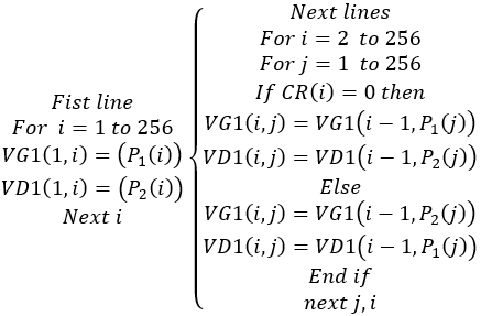
The generation of the two matrices (VG1) and (VD1) is determined by the following algorithm
|
Algorithm 5. Dynamic S-Box Building |
2.7 Classic Vigenere function expression
These two matrices will be used together in the encryption process and will be completely under vector control $(VC)$. We remember to pass Vigenere's classic replacement function through the following formula
$\{Y(i)=V G 1(K, X(i))$ (7)
(K) key duplicated to the size of the text to be encrypted.
2.8 New Vigenere’s mathematica expression
The following equation illustrates the effective expression of the $Y(i)$ image of the pixel $X(i)$ through the new Hill technology.
|
Algorithm 6. Replacement functions construction |
|
$V_{1}(X(i))=$ |
We notice that the replacement function of the first round is supervised by the control binary vector (RC). This ensures that when a single bit in the vector (RC) is modified, a new replacement function will be generated.
2.9 First-round spread function expression
The first round will be equipped with a powerful diffusion function to connect encrypted pixels with subsequent transparent pixels to increase the impact of the avalanche effect and protect the system from any differential attacks. The expression of this new diffusion function is given by the formula below
$\forall \mathrm{i}>1 \Phi(X(i))=V D 1\left(M L(i), X^{\prime}(i-1) \oplus X(i)\right)$ (8)
2.10 The first-round analysis
This first round is defined by the following algorithm,
We note: $V_{1}(X(\mathrm{i}))=Y(i)$ (9)
So
|
Algorithm 7. 2st initialization value computing |
|
$\left\{\begin{array}{c}X^{\prime}(1)=I V 1 \oplus X(1) \\ Y(1)=V_{1}\left(X^{\prime}(1)\right) \\ \text { For } i=2 \text { to } 3 \mathrm{~nm} \\ \alpha=\Phi(X(i)) \\ Y(i)=V_{1}(\alpha) \oplus K R(i) \\ \text { Next } i\end{array}\right.$ |
Figure 1 below shows the first round
Figure 1. First round
At the end of the first round, the output vector (Y) will be treated as a clear image to be applied to the second round of encryption. The output vector is subdivided into three blocks of size (1, nm) for future gene mutations.
Step5: Genetic Mutation
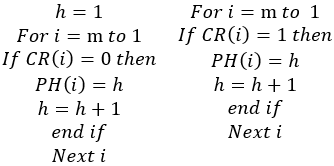
The output vector is subdivided into (m) blocks of (3n) pixels each as well as the chaotic vector (CL), for future chaotic mutation between the two vectors. This operation will be supervised by the (PH) permutation vector obtained by a broad ascending sort on the binary vector (BC) and generate by the following process:
|
Algorithm 8. (PH) computing |
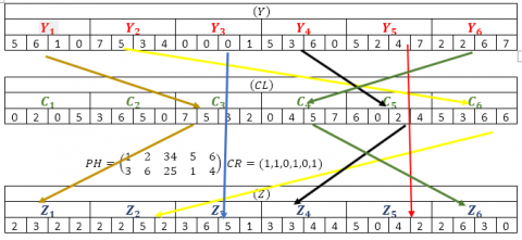
The mutation function is the confusion of the original sub-block with the chaotic sub-block only in the case where the bit of the vector (CR) is not zero. This operation is defined by the following algorithm
|
Algorithm 9. Mutation's new expression |
Example:
Step6: Second Vigenere round
At the end of the first round, the new (IV2) initialization value will be calculated according to the following algorithm.
|
Algorithm 10. Second initialization value |
|
$\left\{\begin{array}{c}\text { for } i=2 \text { to } 3 \mathrm{~nm} \\ I V 2=I V 2 \oplus Y(i) \\ \text { Next } i\end{array}\right.$ |
In the second round, by simply replacing the position of the replacement matrix, the output vector will be treated as a new image to be encrypted by the same method as the first round.
2.11 Second round analysis
The second round can also be ensured by using a different same matrix in the first round.
|
Algorithm 11. Vigenere's second function |
|
$V_{2}(X(i))=$ |
The same mold will be used in the second round, but in a different way.
2.11.1 Second-round spread function expression
The second round will be equipped with the diffusion $(\Omega)$ ensured by the replacement matrix generated. The expression of this function is defined by the following notation:
|
Algorithm 12. Second function of diffusion |
|
$\forall \mathrm{i}>1 \Omega(X(i))=V D 1\left(M L(i), X^{\prime}(i-1) \oplus X(i)\right)$ |
2.11.2 The second-round analysis
This second round is defined by the following algorithm:
|
Algorithm 13. 2° round function |
|
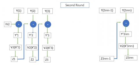
$\left\{\begin{array}{c}Y^{\prime}(1)=I V 2 \oplus Y(1) \\ Z(1)=V_{2}\left(Y^{\prime}(1)\right) \\ \text { For } i=2 \text { to } 3 \mathrm{~nm} \\ \alpha=\Omega(Y(i)) \\ Z(i)=V_{2}(\alpha) \\ N e x t i\end{array}\right.$ |
Figure 1.1 below shows the first round.
Figure 1.1. Second round
The output vector (Z) will be subjected to a permutation (RH) obtained by sorting on the vector (CR) by the same process). This permutation is applied to increase the complexity of our system It is defined by the following algorithm:
|
Algorithm 14. Permutation application |
|
$\left\{\begin{array}{c}\text { For } i=1 \text { to } 3 n m \\ Z C(i)=P H(Z(i)) \\ \text { Next } i\end{array}\right.$ |
The vector (ZC) constitutes the image encrypted by our algorithm.
Step7: Decryption of encrypted images
In the literature, the classic Vigenere method uses the same matrix in both processes. Our contribution in this work is that the matrix used in encryption is different from the matrix used in decryption. Therefore, the calculation of the decryption matrix is necessary.
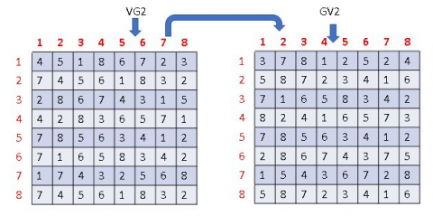
2.12 Decryption matrix structure
Each row of the encrypted S-box is a permutation in $\left(G_{256}\right)$, so the decryption matrix will consist of reverse permutations. For this reason, two decrypted $S-B o x$ generations are given by the following algorithm:
|
Algorithm 15. Vigenere inverse matrices |
|
$\left\{\begin{array}{c}\text { for } i=1 \text { to } 256 \\ \text { for } j=1 \text { to } 256 \\ \text { VG2 }(i, V G 1(i, j))=j \\ V D 2(i, V G 2(i, j))=j \\ \text { Next } j, i\end{array}\right.$ |
2.12.1 Decryption matrix structure
Each row of the encrypted S-box is a permutation in $\left(G_{256}\right)$, so the decryption matrix will consist of reverse permutations. For this reason, two decrypted $S-B o x$ generations are given by the following algorithm:
|
Algorithm 16. Inverse Matrices |
|
$\left\{\begin{array}{c}\text { for } i=1 \text { to } 256 \\ \text { for } j=1 \text { to } 256 \\ \operatorname{VG} 2(i, V G 1(i, j))=j \\ \operatorname{VD} 2(i, V G 2(i, j))=j \\ N e x t j, i\end{array}\right.$ |
Example
The decryption process will follow the following reverse steps
2.12.2 Reverse permutation
The inverse permutation (HP) of (PH) is given by the following algorithm:
|
Algorithm 17. Inverse permutation |
|
$\left\{\begin{array}{c}\text { For } i=1 \text { to } 3 \mathrm{~nm} \\ H P(P H(i))=i \\ \text { Next } i\end{array}\right.$ |
After vectorization of the image encrypted in vector (ZC) an intervention of the permutation (HP) to recover the vector (Z).
This operation is determined by the following algorithm:
|
Algorithm 18. Inverse permutation application |
|
$\left\{\begin{array}{c}\text { For } i=1 \text { to } 3 \mathrm{~nm} \\ Z(i)=H P(Z C(i)) \\ \text { Next } i\end{array}\right.$ |
2.12.3 The reciprocal of the Second lap function
This step is given by the algorithm below:
|
Algorithm 19. Second lap Invers |
|
$\left\{\begin{array}{c}\text { For } i=3 n m \text { to } 1 \\ Y(i)=V_{2}^{-1}(Z(i)) \oplus Z(i-1) \\ N E x t i\end{array}\right.$ |
A recalculation of the initialization value will make it possible to retrieve the exact value of pixel Y(1).
2.12.4 The reverse mutation
In general, mutation is an involutive operation, therefore we have
|
Algorithm 20. Reverse mutation |
|
$(M t)^{-1}=M t$ |
In order to measure the performance of our encryption system, we randomly select a large number of reference images, and then use our method to test them. In this part, all experiments are performed under the Matlab software running under Windows 7, on a basic i7 personal computer, 16 GB RAM, and 500 GB hard disk.
3.1 Key-space analysis
The chaotic sequence used in our method ensures strong sensitivity to initial conditions and can protect it from any brutal attacks. The secret key to our system consists of
|
Key size |
|
Logistic map u0=0,7655412001, μ=3.89231541 PWLCM v0=1,3561 p=0.623 SKTM w0=1,3561 d=0.752 |
If we use single-precision real numbers 10^{-10} to operate, the total size of the key will greatly exceed $\approx 10^{-60} \gg 2^{180} \gg 2^{110}$, which is enough to avoid any brutal attacks.
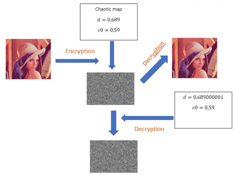
3.2 Secret key’s sensitivity analysis
Our encryption key has a high sensitivity, which means that a small degradation of a single parameter used will automatically cause a large difference from the original image. The image below illustrates this confirmation:
We notice that a tiny perturbation on a single element of the secret key, will generate a random decrypted image that is clearly different from the original image. This ensures a high sensitivity to the secret key, and therefore, in the absence of the real encryption key, the original image cannot be restored.
3.3 Statistics attack security
3.3.1 Entropy analysis
The entropy of an image of size (n,m) is given by the equation below
$H(M C)=\frac{1}{t} \sum_{i=1}^{t}-p(i) \log _{2}(p(i))$ (10)
$p(i)$ is the probability of occurrence of level (i) in the original image attendance.
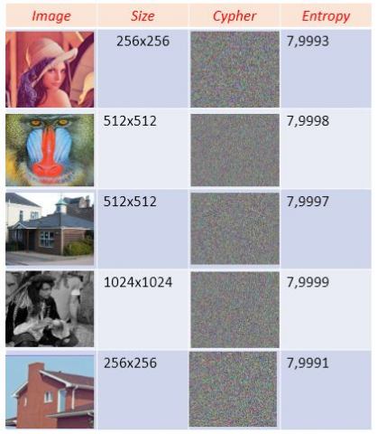
Table 1. Entropy of some tested images
We noticed that the entropy of all images tested by our algorithm is close to 8, which is the maximum value. These values ensure that our system is protected from entropy attacks (Table 1).
3.3.2 Correlation analysis
The correlation of an image of size (n,m) is given by the equation below
$r=\frac{\operatorname{cov}(x, y)}{\sqrt{V(x)} \sqrt{V(y)}}$ (11)
Table 2. Correlation of some tested images
Pixel correlation measures the independence of neighboring pixels. All the correlation measures of the images tested by our system are very close to zero. This can protect our methods from statistical attacks (Table 2).
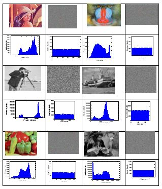
3.3.3 Histogram analysis
All images tested by our algorithm have a uniformly distributed histogram. This reflects that the entropy of the encrypted images is around 8, which makes the system immune to histogram attacks (Table 3).
Table 3. Encrypted image histogram
3.4 Differential analysis
In cryptography, differential attacks are managed by the following constants.
3.4.1 The NPCR constant
It is determined by the equation below
$N P C R=\left(\frac{1}{n m} \sum_{i, j=1}^{n m} D(i, j)\right) * 100$
$D(i, j)=\left\{\begin{array}{lll}1 & \text { if } & C_{1}(i, j) \neq C_{2}(i, j) \\ 0 & \text { if } & C_{1}(i, j)=C_{2}(i, j)\end{array}\right.$ (12)
3.4.2 The UACI constant
The UACI mathematical analysis of an image is given by the next equation
$U A C I=\left(\frac{1}{n m} \sum_{i, j=1}^{n m} A b s\left(C_{1}(i, j)-C_{2}(i, j)\right)\right) * 100$ (13)
3.4.3 Signal-To-Peak Noise Ratio (PSNR)
(1) MSE
The MSE mathematical analysis of an image is given by the next equation
$M S E=\sum_{i, j}\left(P(i, j)-C(i, j)^{2}\right.$ (14)
(2) PSNR
The PSNR mathematical analysis of an image (Table 4) is given by the next equation
$P S N R=20 \log _{10}\left(\frac{I_{\max }}{\sqrt{M S E}}\right)$ (15)
Table 4. Differential parameters
3.4.4 Avalanche effect
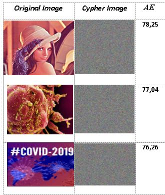
Table 5. Avalanche effect
Our algorithm uses a strong link between encrypted pixels and subsequent clear pixels in the strategy. This leads to a gradual change in the value, which becomes more and more important as the data spreads through the structure of the algorithm. The avalanche effect is the number of bits that have been changed if a single bit of the original image is changed (Table 5). The mathematical expression of this avalanche effect is given by
$A E=\left(\frac{\sum_{i} \text { bit change }}{\sum_{i} \text { bit total }}\right) * 100$ (16)
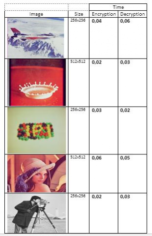
3.4.5 Performance time
In our technique, the encryption and decryption times (Table 6) are very similar and vary in the interval $[0,050,1]$.
Table 6. Encryption time
Our encryption keys are large, which can ensure that the new system is protected from brute force attacks. At the same time, the randomness of the operators described in the system makes it difficult to unlock any encrypted images, which increases the difficulty of statistical attacks. In addition, due to the high sensitivity to the initial parameters of our three chaotic cards, and the broadcast installed in each tower confirmed the robustness of our encryption system.
Due to their high sensitivity to initial conditions, chaotic systems are widely used in color image encryption. with an improvement of the Vigenere matrices, we have, in our strategy, developed two alternative matrices based on two chaotic maps for the execution of two Vigenere towers. Two start-up settings were computed to initiate the process of diffusing confusion between the encrypted block and the next clear block, to significantly augment the avalanche action and to prevent the system from known differential attacks. All the statistical constant values derived from our analysis can ensure that our software is not exposed to known attacks.
|
Notation |
|
$\left\{\begin{array}{c}G_{t}=Z / t Z \text { ring } \\ G_{t}^{*}=\text { Set of } G_{t} \text { reversers } \\ \oplus \text { Binary addition } \\ A(j:): \text { Line number } j \text { of matrix } A \\ A(: j): \text { colunm number } j \text { of matrix } A\end{array}\right.$ |
[1] Rachmawanto, E.H., De Rosal, I.M.S., Sari, C.A., Agus Santoso, H., Rafrastara, F.A., Sugiarto, E. (2019). Block-based Arnold chaotic map for image encryption. 2019 International Conference on Information and Communications Technology (ICOIACT), pp. 174-178. https://doi.org/10.1109/ICOIACT46704.2019.8938443
[2] Bansal, R., Gupta, S., Sharma, G. (2017). An innovative image encryption scheme based on chaotic map and Vigenère scheme. Multimedia Tools and Applications, 76: 16529-16562. https://doi.org/10.1007/s11042-016-3926-9
[3] Jarjar, A. (2017). Improvement of hill’s classical method in image cryptography. International Journal of Statistics and Applied Mathematics, 2(3): 37-43.
[4] Saputra, I., Hasibuan, N.A., Rahim, R. (2017). Vigenere cipher algorithm with grayscale image key generator for secure text file. International Journal of Engineering Research & Technology (IJERT), 6(1): 266-269.
[5] Reddy, V.V.K., Bhukya, S. (2018). Encrypt and decrypt image using Vigenere cipher. International Journal of Pure and Applied Mathematics, 118(24): 1-8.
[6] Kester, Q.A. (2012). A cryptosystem based on Vigenère cipher with varying key. International Journal of Advanced Research in Computer Engineering & Technology (IJARCET), 1(10): 108-113.
[7] Dewangga, I.G.A.P., Purboyo, T.W., Nugrahaeni, R.A. (2017). A new approach of data hiding in BMP image using LSB steganography and Caesar Vigenere cipher cryptography. International Journal of Applied Engineering Research, 12(21): 10626-10636.
[8] Rahmani, K.I., Wadhwa, N., Malhotra, V. (2012). Alpha-Qwerty cipher: An extended Vigenere cipher. Advanced Computing, 3(3): 109. https://doi.org/10.5121/acij.2012.3311
[9] Boussif, M., Aloui, N., Cherif, A. (2020). Securing DICOM images by a new encryption algorithm using Arnold transform and Vigenère cipher. IET Image Processing, 14(6): 1209-1216. https://doi.org/10.1049/iet-ipr.2019.0042
[10] Peng, J., Liao, X., Wu, Z. (2002). Digital image secure communication using Chebyshev map chaotic sequences. In IEEE 2002 International Conference on Communications, Circuits and Systems and West Sino Expositions, pp. 492-496. https://doi.org/10.1109/ICCCAS.2002.1180666
[11] Hraoui, S., Gmira, F., Jarar, A.O., Satori, K., Saaidi, A. (2013). Benchmarking AES and chaos based logistic map for image encryption. In 2013 ACS International Conference on Computer Systems and Applications (AICCSA), pp. 1-4. https://doi.org/10.1109/AICCSA.2013.6616441
[12] François, M., Grosges, T., Barchiesi, D., Erra, R. (2012). A new image encryption scheme based on a chaotic function. Signal Processing: Image Communication, 27(3): 249-259. https://doi.org/10.1016/j.image.2011.11.003
[13] Shah, A. (2016). Enhancing security of Vigenere cipher using modified RC4. International Journal of Computer Applications, 136(5): 38-41. https://doi.org/10.5120/ijca2016908428
[14] Li, H., Wang, Y., Zuo, Z. (2019). Chaos-based image encryption algorithm with orbit perturbation and dynamic state variable selection mechanisms. Optics and Lasers in Engineering, 115: 197-207. https://doi.org/10.1016/j.optlaseng.2018.12.002
[15] Ge, R., Yang, G., Wu, J., Chen, Y., Coatrieux, G., Luo, L. (2019). A novel chaos-based symmetric image encryption using bit-pair level process. IEEE Access, 7: 99470-99480. https://doi.org/10.1109/ACCESS.2019.2927415
[16] Jarjar, M., Najah, S., Zenkouar, K., Hraoui, S. (2020). Further improvement of the HILL method applied in image encryption. In 2020 1st International Conference on Innovative Research in Applied Science, Engineering and Technology (IRASET), pp. 1-6. https://doi.org/10.1109/IRASET48871.2020.9092046
[17] Saputra, I., Mesran, Hasibuan, N.A., Rahim, R. (2017). Vigenere cipher algorithm with grayscale image key generator for secure text file. International Journal of Engineering Research & Technology (IJERT), 6(1): 266-269.
[18] Zhang, L., Zhang, X. (2020). Multiple-image encryption algorithm based on bit planes and chaos. Multimedia Tools and Applications, 79(29): 20753-20771. https://doi.org/10.1007/s11042-020-08835-4
[19] Enayatifar, R., Guimarães, F.G., Siarry, P. (2019). Index-based permutation-diffusion in multiple-image encryption using DNA sequence. Optics and Lasers in Engineering, 115: 131-140. https://doi.org/10.1016/j.optlaseng.2018.11.017
[20] Belazi, A., El-Latif, A.A.A., Belghith, S. (2016). A novel image encryption scheme based on substitution–permutation network and chaos. Signal Processing, 128: 155-170. https://doi.org/10.1016/j.sigpro.2016.03.021
[21] Hua, Z., Zhou, Y., Pun, C.M., Chen, C.L.P. (2015). 2D Sine Logistic modulation map for image encryption. Information Sciences, 297: 80-94. https://doi.org/10.1016/j.ins.2014.11.018