Zhenggang Guo | Juan Wang | Shuai Lv | Deyue Yu | Xu Zhang*
© 2020 IIETA. This article is published by IIETA and is licensed under the CC BY 4.0 license (http://creativecommons.org/licenses/by/4.0/).
OPEN ACCESS
In unstable coal rock formations, the rescue channels should be constructed through safe and efficient tunneling. The rock breaking performance of the tunneling equipment directly hinges on the cutter-head layout. Focusing on the conditions of unstable coal rock formation, this paper adopts the extended Drucker-Prager (D-P) plastic model to define the properties of bedrock materials of the coal rock with low mechanical strength and poor homogeneity. Then, a finite-element model was established on ABAQUS for the coal rock cut by two disc cutters, and used to simulate the breaking of the coal rock and the peeling of slags from the bedrock. On this basis, the authors analyzed the influence of cutter spacing (30, 35, 40, and 45mm) over cutting force, rock breaking amount, and specific energy under two cutting methods: simultaneous cutting and sequential cutting. Finally, a cutter deployment strategy was designed for safe and efficient tunneling in unstable coal rock formations. The results show that: Under simultaneous cutting, as the cutter spacing increased from 30 to 35mm, the rock breaking amount increased, while the specific energy declined; as the cutter spacing further rose from 35 to 45mm, the rock breaking amount dropped, while the specific energy increased. Under the coal rock conditions in our research, the optimal cutter deployment strategy is: simultaneous cutting with cutter spacing of 35mm. The research results provide theoretical support for the cutter-head design of rescue equipment for collapsed coalmines.
tunnel boring machine (TBM), two disc cutters, coal rock breaking principle, cutter spacing
Underground disasters seriously threaten the work safety in coalmines. Once an accident occurs, the mine system will be severely damaged. This will not only interrupt production, but also block the evacuation channels, resulting in heavy casualties [1, 2]. If the coalmine collapses, the post-disaster rescue must be provided urgently, and implemented safety to prevent further damage induced by secondary collapse [3]. Hence, safe and efficient tunneling is the key technology for the rapid construction of rescue channels in collapsed coalmines.
The pipe jacking machine is a large engineering equipment for laying underground pipelines [4]. With a simple structure, the machine can be assembly easily and supports rapid excavation. These advantages have made it a hot topic in the research of the rapid construction of rescue channels in collapsed coalmines [5]. When the pipe jacking machine advances in the coal rock formation, the spinning cutter-head drives the disc cutter to break the coal rock. To realize safe and efficient tunneling of collapsed coal rock formation by pipe jacking machine, it is important to study the factors affecting the coal rock breaking effect of the disc cutter.
In recent years, fruitful results have been achieved on the rock breaking principle of multiple disc cutters through theoretical analyses, experiments, and numerical simulations, providing reference for our research into the rock breaking effect of disc cutters. Some of the most representative theoretical analyses and experiments are as follows: Gertsch et al. [6] cut different hard rocks with disc cutters, examined the effects of cutter spacing and penetration on cutting force and cutting performance, and summarized the relationship between the forces in three directions and the specific energy. Chang et al. [7] conducted a linear cutting test on a specific granite with a 17-inch disc cutter, and derived the optimal cutter spacing and penetration. Gong et al. [8] analyzed the forces in three directions and specific energy under different penetrations and cutter spacings, and obtained the set of parameters that maximizes the rock breaking efficiency.
Considering the high cost and long duration of indoor rock breaking tests and the limitations in simulating the complex geological conditions of the tunneling site, many researchers have numerically simulated the rock breaking process [9]. Jaime et al. [10] analyzed the rock failure modes during disc cutting on LS-DYNA, and simulated two rock failure modes under different penetrations. Relying on finite-element method and extended Drucker-Prager (D-P) nonlinear elastoplastic constitutive model, Cheng [11] performed three-dimensional (3D) dynamic simulation of the rock cutting process with two disc cutters, investigated the features of cutter-rock interaction, and verified the simulation results on a rotary cutting test bench. Moon and Oh [12] conducted discrete-element simulation of the rock breaking process with disc cutters at different penetrations and cutter spacings, verified the simulation results on a rock cutting test bench, and obtained the optimal S/P value. Through discrete-element simulation, Tan et al. [13] clarified the mapping relationship between the cutter length into rock crack and penetration, and deduced the theoretical formula of the optimal cutter spacing.
In addition, Cho and Lee [14] carried out discrete-element analysis on the rock breaking force and rock breaking mechanism of disc cutters under different joint spacings and joint directions. Labra et al. [15] combined discrete-element method with finite-element method for numerical simulation, constructed an optimization model to analyze the stress distributions and pressure distributions of cutter-rock interaction with or without precutting, and explored the influence of penetration and cutter spacing over rock breaking process. Cho et al. [16] tested the rock breaking by linear cutting machine (LCM) on AUTODYN-3D to disclose the variation in specific energy with cutter speed and size, and numerically simulated the optimal cutter spacings of eight isotropic homogeneous rocks; the simulation results agree well with the LCM test results. Following two-dimensional (2D) discrete-element method, Naghadehi and Mikaeil [17] numerically simulated the spalling process of jointed hard rock under the indentation of two types of cutters of tunnel boring machine (TBM), and optimized the cutter spacing based on the simulation results. Taking granite as an example, Zhou et al. [18] simulated the rock breaking process with two disc cutters, and analyzed the rock breaking effect at different cutter spacings.
The above studies probe deep into the rock breaking principle of multiple disc cutters, and the influence of cutter spacing on the breaking of hard and soft rocks. However, there is no report on the coal rock breaking with disc cutter. The research and development (R&D) of the pipe jacking machine for coalmine rescue is still in the exploratory stage. It is very meaningful to explore the mechanism and conduct simulation of coal rock breaking with multiple disc cutters. The relevant findings will promote the design of cutter-head layout, optimization of disc cutter structure, and the decision-making of tunneling control [19].
For the special conditions of coal rock, this paper carries out finite-element simulation of coal rock breaking with two disc cutters at different cutting methods and cutter spacings. Then, the principle of coal rock breaking with two disc cutters was analyzed theoretically, and the tunneling plan was evaluated from the angles of tunneling efficiency and safety. On this basis, the cutter spacing was optimized for the specific coal rock conditions. The research results promote the evaluation of the tunneling performance of the pipe jacking machine for coalmine rescue.
2.1 Rock breaking principle of two disc cutters
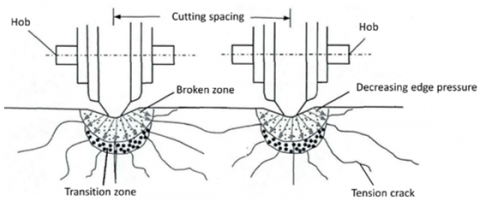
When a single disc cutter cuts the rock, the rock deforms and cracks under the cutter pressure. The crack will propagate continuously, and eventually destroy the rock. In actual engineering, multiple disc cutters on the cutter-head of the TBM work simultaneously or sequentially. The two adjacent disc cutters break the rock in the following process: a stress concentration area (SCA) is formed under each blade. Cracks will appear first on the weak positions on the sides of the blade. Under the continuous action of the vertical cutter force, the SCAs under the two blades will interact with each other; the cracks on both sides of each blade will continue to develop, and converge at the middle of the two adjacent disc cutters [20]. Figure 1 explains the rock breaking principle with adjacent disc cutters.
Figure 1. The rock breaking principle with adjacent disc cutters
2.2 Selection of constitutive model
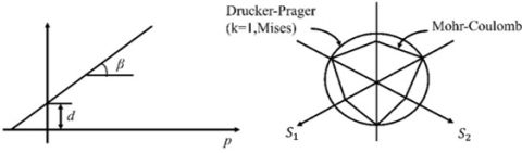
The load features of disc cutters are closely related to the coal rock material model. The coal rock generally has a nonlinear constitutive relationship, which depends on not only the type of rock, but also the stress history, loading path, and stress level. Liu et al. adopted the extended DP model to simulate the rock-breaking process of cutters, disc cutters, and polycrystalline diamond compact (PDC) drill bits, and achieved good simulation results. Therefore, this paper employs the extended D-P plastic model to simulate the constitutive relationship of coal rock [20-22]. Figure 2 shows the yield surface used in the linear D-P model. The yield function and the elastic potential surface can be respectively defined as:
$F=t-p \tan \beta-d=0$ (1)
$G=t-\operatorname{ptan} \varphi$ (2)
where,
$t=\frac{q}{2}\left[1+\frac{1}{k}-\left(1-\frac{1}{k}\right) \frac{r^{3}}{q}\right]$ (3)
where, t is the deviatoric stress; p is the equivalent compressive stress; β is the friction angle of the material; d is the cohesion; φ is the dilatancy angle; r is the third invariant of the deviator; k is the ratio of uniaxial tensile yield stress to uniaxial compressive yield stress; q is the Mises equivalent stress.
Figure 2. The linearly extended D-P yield criterion in the π plane
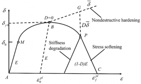
The rock breaking process of disc cutters is a typical rock failure process, from deformation, damage, to cracking. Figure 3 shows the damage and failure model of the rock based on fracture mechanics. The finite-element method introduces the element deletion function to simulate this failure process: the material response in section A-B before the element failure, the initial failure at point B (determined by the initial damage criterion), and the damage evolution law in B-C section. In Figure 3, the material in section A-B belongs to the elastoplastic deformation phase. When the material stress reaches the strength limit, the initial damage criterion can be established based on the shear failure criterion, according to the equivalent plastic strain of the element integration point:
$\omega_{s}=\int \frac{d \bar{\varepsilon}^{p l}}{\overline{\varepsilon_{s}} p l\left(\theta_{s}, \bar{\varepsilon}^{p l}\right)}=1$ (4)
where, $\theta_{s}=(q+K p) / \tau_{\max }$ is the shear stress rate ($\tau_{\max }$ is the maximum shear stress); $\dot{\bar{\varepsilon}}^{p l}$ is the shear strain rate.
2.3 Establishment of finite-element model
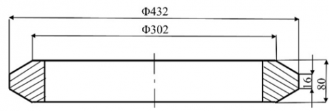
The disc cutters selected for this research are 17-inch. Since the cutter ring is the only part in direct contact with the rock during the rock breaking process, components like cutter shaft and snap ring were neglected to simplify the finite-element model. Then, the actual structural size of the 17-inch disc cutters in Figure 4 was used to establish a 3D model.
The disc cutters are made of hard alloy steel, whose density ρ is 7,850kg/m3, elastic modulus E is 210GPa, and Poisson’s ratio ν is 0.3. Due to the complex composition of the collapsed rock mass, the basic parameters of the coal rock were configured as shown in Table 1.
Figure 3. The damage and failure model of the rock
Figure 4. The size of the 17-inch disc cutters
Table 1. The coal rock parameters
|
Density ρ/kg•m-3 |
Elastic modulus E/MPa |
Friction angle φ/(°) |
Flow stress ratio |
Yield stress/MPa |
Poisson’s ratio μ |
|
1500 |
1400 |
30.2 |
0.778 |
20.49 |
0.3 |
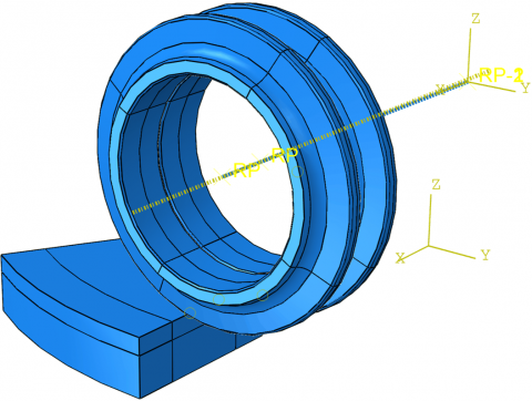
The finite-element model of the coal rock to be broken by two disc cutters is illustrated in Figure 5. The model is composed of C3D8R hexahedral elements. The elements were refined on the cutter ring, and full constraints were imposed on the rock bottom.
Figure 5. The finite-element model of the coal rock cut by two disc cutters
2.4 Simulation plan
The tunneling performance of TBM is closely related to the cutter layout on the cutter-head. Since the cutters are arranged on circles of different diameters, the positional relationship of adjacent cutters can be described by phase angle and cutter spacing. By phase angle, the cutting behaviors of multiple cutters can be divided into two types: simultaneous cutting and sequential cutting.
Cutter spacing has a major impact on the TBM tunneling performance. If the cutter spacing is too large, the rock will not be sufficiently broken; if the cutter spacing is too small, the slags cannot be discharged smoothly via the gap between two adjacent cutters [23]. If the target stratum is stable, the optimal cutter spacing should break the largest amount of rocks at the lowest energy cost. If the target stratum is unstable, the influence of cutter spacing over the rock breaking amount, energy consumption, and tunneling stability must be considered comprehensively, and the cutter spacing should strike a balance between tunneling efficiency and safety.
Table 2. The simulation plan
|
Groups |
Test number |
Fixed parameters |
Test parameter |
|
|
Group 1 |
1 |
Penetration: 4mm; Loading method: simultaneous cutting |
Cutter spacing/mm |
30 |
|
2 |
35 |
|||
|
3 |
40 |
|||
|
4 |
45 |
|||
|
Group 2 |
5 |
Penetration: 4mm; Loading method: sequential cutting |
Cutter spacing/mm |
30 |
|
6 |
35 |
|||
|
7 |
40 |
|||
|
8 |
45 |
|||
To better analyze the rock breaking effect of unstable coal rock with disc cutters, ABAQUS finite-element simulations of simultaneous cutting and sequential cutting (phase angle α=60°) were conducted at the same cutting speed (0.4rad/s) and the same penetration (4mm), but different cutter spacings (30, 35, 40, and 45mm). The simulation plan is detailed in Table 2.
2.5 Performance indices
Based on the simulation results, the trends of specific energy, rock breaking amount, and cutting force were analyzed under different loading methods and cutter spacings, the influence of cutter parameters over tunneling performance was evaluated, and the optimal cutter spacing was determined for efficient and safe tunneling. The evaluation indices are introduced as follows:
(1) Specific energy (SE)
Specific energy is an important indicator of the energy consumption of rock breaking. It refers to the energy consumed by cutting a unit volume of rock [24]. The smaller the specific energy, the less energy consumed by cutting per unit volume of rock. The specific energy can be calculated by:
$S E=\frac{F_{R} \times l_{Z}}{\omega_{r} / \rho_{r}}=\frac{F_{R} \times l_{Z}}{V}$ (5)
where, FR is the mean rolling force; lz is the cutting length; ωr is the mass of slags produced in the cutting process; ρr is the rock density; V is the volume of slags.
(2) Rock breaking amount
During rock cutting, rock breaking amount measures the reasonability of the cutter spacing arrangement [25]. In our experiments, the rock breaking amount was calculated after weighing the slag mass. Under fixed mean rolling force and cutting length, the greater the rock breaking amount, the smaller the specific energy, and the more efficient the rock breaking process. The rock breaking amount V1 can be calculated by:
$V_{1}=\frac{N_{0}-N_{1}}{N_{1}} \cdot V_{0}$ (6)
where, V0 is the initial volume of the rock model; N0 is the total number of initial elements in the rock model; N1 is the total number of initial elements in the rock model after cutting.
(3) Cutting force
Cutting force is an important factor affecting tunneling efficiency and safety. During tunneling, a large cutting force is generally favorable for tunneling efficiency, but not conducive to the stability of the coal-rock interface. If the coal rock formation is unstable, the TBM tunneling control hinges on the reasonability of the cutting force. According to the rock breaking mechanism of two disc cutters, cracks appear in the rock under the vertical force from the cutters, and propagate across and penetrate the rock, causing the slags to peel off from the rock. Therefore, the vertical force of the cutters was adopted to measure the cutting force.
3.1 Simulation results on simultaneous cutting
Figure 6 presents the stress cloud maps of the coal rock with the cutter spacings of 30, 35, 40, and 45mm. Judging by the stress distribution and breaking situation of the coal rock, the maximum stress appeared in the coal rock areas in contact with the disc cutters; the broken area and breaking amount gradually increased with the expansion of the strain area of the rock mass. The strain of the rock was distributed symmetrically across the broken area; as the broken area expanded outward, the stress gradually declined. When the cutter spacing was 30mm, the breaking amount was relatively small, and virtually no ridge was observed in the broken zone; when the cutter spacing increased to 35mm and 40mm, a slight ridge appeared on the surface of the coal rock, which disintegrated and disappeared as the cutters rolled forward; when the cutter spacing rose to 45mm, a ridge appeared in the broken zone and remained there. These results suggest that, under the coal rock conditions in our research, the tunneling efficiency of two disc cutters is optimized, when the cutter spacing falls between 35mm and 40mm.
Figure 6. The stress cloud maps under simultaneous cutting at different cutter spacings
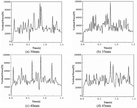
Figure 7 shows the vertical force curves of the two disc cutters during simultaneous cutting of the coal rock. From Figures 6 and 7, it can be seen that, under the simultaneous action of the two disc cutters, the damage in the coal rock developed into cracks, which grew continuously until the slags peel off the parent rock. During this process, the contact area between the coal rock and each cutter was gradually compressed, and the vertical force increased accordingly; when the rock breaking force of the cutters increased to the yield limit of the rock, the coal rock was broken, and the vertical force was reduced. With the growing cutter spacing, the mean vertical force increased linearly, but the amplitude of the vertical force did not change significantly.
Figure 7. The vertical force curves under simultaneous cutting
Table 3 lists the parameters of rock breaking performance under simultaneous cutting of two disc cutters at different cutter spacings. As the cutter spacing increased from 30 to 35mm, the rock breaking amount increased, while the specific energy declined; as the cutter spacing further rose from 35 to 45mm, the rock breaking amount dropped, while the specific energy increased. Therefore, the highest tunneling efficiency was achieved at the cutter spacing of 35mm. Considering the impact of cutter force, construction efficiency, and tunneling safety, the optimal cutter spacing for tunneling in unstable coal rock stratum was determined as 35mm.
Table 3. The simulation results on rock breaking performance under simultaneous cutting of two disc cutters
|
Cutter spacing S/mm |
Mean vertical force FV/kN |
Rock breaking amount Q/m3 |
Specific energy SE/MJ/m3 |
|
30 |
35.2 |
0.000193 |
7.09 |
|
35 |
36.7 |
0.000195 |
6.78 |
|
40 |
37.1 |
0.000186 |
7.41 |
|
45 |
37.3 |
0.000182 |
7.82 |
3.2 Simulation results on sequential cutting
With the phase angle of α=60°, two disc cutters cut the coal rock sequentially at the same speed. Figure 8 presents the stress cloud maps of the coal rock with the cutter spacings of 30, 35, 40, and 45mm. Judging by the stress distribution and breaking situation of the coal rock, the stress distribution under sequential cutting was nonuniform, and the stress on and within the coal rock was not distributed symmetrically across the broken zone. Besides, the slag volume increased with the cutter spacing. As shown in Figures 9(a) and 9(b), when the cutter spacing was relatively small, most of the coal rock between the two cutters belonged to the broken zone, and the rock breaking energy of the cutters was fully unleashed. As shown in Figures 9(c) and 9(d), when the cutter spacing was too large, the cracks induced by each cutter did not propagate sufficiently, creating a long-lasting ridge between the two cutters. In this case, the rock breaking energy of the cutters was not fully utilized. The tunneling efficiency at the cutter spacing of 30-35mm was much higher than that of 40-45mm.
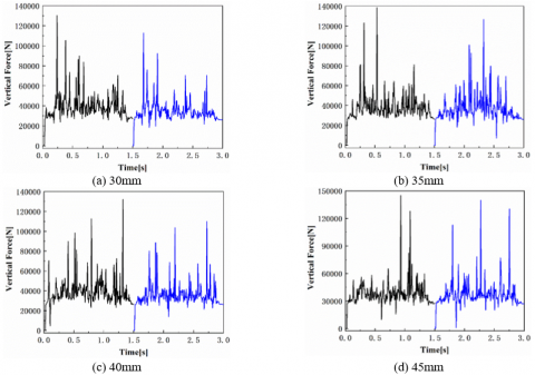
Figure 9 shows the vertical force curves of the two disc cutters during sequential cutting of the coal rock. It can be seen that, under each cutter spacing, the two disc cutters differed slightly in the mean vertical force, but the peak vertical force of the first cutter was greater than that of the second cutter. This is because the first cutter rolled over the rock in the manner of single cutter rock breaking, while the second cutter followed up in the manner of two-cutter collaborative rock breaking; under the impact of the first cutter, dense parts and cracks form within the rock, reducing the reaction force to the second cutter. With the growing cutter spacing, the mean and peak of vertical forces of both cutters were on the rise. The reason is that a large cutter spacing means a wide area of the cutting target; the powdery slags will change into flaky and blocky slags, which cannot be broken under a limited vertical force. Moreover, the rock breaking is dominated by compressive failure, as the collaboration between the two cutters weakens. Then, the cutters will suffer from a larger impact. To sum up, a small cutter spacing is beneficial for stable tunneling in an unstable coalmine formation.
Figure 8. The stress cloud maps under sequential cutting at different cutter spacings
Figure 9. The vertical force curves under sequential cutting
Table 4 lists the parameters of rock breaking performance under sequential cutting of two disc cutters at different cutter spacings. At the cutter spacing of 35mm, the specific energy was minimized at 6.84MJ/m3; as the cutter spacing increased from 30 to 35mm, the rock breaking amount increased; as the cutter spacing further rose from 35 to 45mm, the rock breaking amount clearly decreased. Considering the impact of construction efficiency, and tunneling safety, the optimal cutter spacing for sequential cutting was determined as 35mm.
3.3 Comparison between two cutting methods
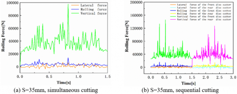
Figure 10 compares the cutter force curves under simultaneous cutting and sequential cutting at the cutter spacing of 35mm. Table 5 lists the simulation results on rock breaking performance of the two cutting methods. It can be seen that, under the same cutter spacing, simultaneous cutting and sequential cutting had little difference in the cutter forces in the three directions; the peak vertical force of sequential cutting was much higher than that of simultaneous cutting. This means, under simultaneous cutting, the collaboration between the two cutters leads to shear failure of the rock, and exerts a relatively small impact. Thus, simultaneous cutting can ensure the tunneling safety. In addition, the two cutting methods were similar in rock breaking efficiency: simultaneous cutting had a slightly smaller specific energy than sequential cutting, and basically the same rock breaking amount as the latter.
The above analysis shows that, when the cutter-head operates in a stable coal rock formation, simultaneous cutting and sequential cutting have basically the same rock breaking effect. However, when the cutter-head operates in an unstable coal rock formation, simultaneous cutting should be adopted as much as possible in cutter-head arrangement, aiming to ensure tunneling safety. Under the coal rock conditions in our research, the optimal cutter deployment strategy is: simultaneous cutting with cutter spacing of 35mm.
Table 4. The simulation results on rock breaking performance under sequential cutting of two disc cutters
|
Cutter spacing S/mm |
Mean vertical force FV/kN |
Rock breaking amount Q/m3 |
Specific energy SE/MJ/m3 |
|
30 |
36.64 |
0.000195 |
7.17 |
|
35 |
37.47 |
0.000199 |
6.84 |
|
40 |
37.72 |
0.000196 |
7.71 |
|
45 |
37.94 |
0.000187 |
8.02 |
Figure 10. The cutter forces under different cutting methods (S= 35mm)
Table 5. The simulation results on different cutting methods at S=35mm
|
|
Vertical force /kN |
Rolling force /kN |
Lateral force /kN |
Rock breaking amount Q/m3 |
Specific energy SE/MJ/m3 |
|
Simultaneous cutting |
36.70 |
3.81 |
0.49 |
0.000195 |
6.78 |
|
Sequential cutting |
37.47 |
3.87 |
0.51 |
0.000195 |
6.84 |
This paper describes the plastic constitutive relationship of coal rock with the extended D-P model, and conducts ABAQUS simulations of the coal rock breaking process with TBM disc cutters. The deformation, crushing, and peeling of the coal rock under the action of two disc cutters were simulated in details. Then, the influence of cutter spacing on cutting force, rock breaking amount, and specific energy were discussed under two cutting methods: simultaneous cutting and sequential cutting. On this basis, the disc cutter layout was optimized to improve the tunneling efficiency and safety in unstable coal rock. The simulation results show that, under simultaneous cutting, as the cutter spacing increased from 30 to 35mm, the rock breaking amount increased, while the specific energy declined; as the cutter spacing further rose from 35 to 45mm, the rock breaking amount dropped, while the specific energy increased. Therefore, the optimal cutter spacing was determined at 35mm. Under sequential cutting, as the cutter spacing increased from 30 to 35mm, the rock breaking amount increased, while the impact of cutting force did not change significantly; the specific energy minimized at the cutter spacing of 35mm. Thus, the optimal cutter spacing is still 35mm. Comparing the two cutting methods, simultaneous cutting achieved a slightly better efficiency than sequential cutting in rock breaking, and a much smaller change amplitude of vertical forces than the latter, suggesting that simultaneous cutting favors the stable tunneling of the cutter-head. Under the coal rock conditions in our research, the optimal cutter deployment strategy is: simultaneous cutting with cutter spacing of 35mm. The research results provide theoretical support for the cutter-head design of rescue equipment for collapsed coalmines.
This work is grateful to the financial supports from National Key R&D Program of China (Grant No.: 2018YFC0808205).
[1] Bahrami, D., Zhou, L., Yuan, L. (2020). Field verification of an improved mine fire location model. Mining, Metallurgy & Exploration. https://doi.org/10.1007/s42461-020-00314-6
[2] Xu, Y., Chang, Q., Yan, X., Han, W., Chang, B., Bai, J. (2020). Analysis and lessons of a mine water inrush accident resulted from the closed mines. Arabian Journal of Geosciences, 13(14): 665. https://doi.org/10.1007/s12517-020-05613-2
[3] He, J.F., Zhao, Z.Q., Yin, Q.L., Luo, Y.J., Gan, X. (2020). Design and optimisation on rapid rescue well-drilling technology with large-diameter pneumatic hammers. International Journal of Mining Reclamation and Environment, 34(1): 19-33. https://doi.org/10.1080/17480930.2018.1514687
[4] Guo, J., Ma B.S., Zhao, Y.S., Chen, X.H., Zai, H.X. (2019). Soil disturbance measurement and analysis of large section rectangular pipe-jacking construction. Special Structures, 36(1): 1-7. https://doi.org/10.3969/j.issn.1001-3598.2019.01.001
[5] Guo, Z.G., Lv, S., Wang, J., Zhang, X. (2020). Rock-breaking performance of cutters of tunnel boring machine in broken coal rock formation. International Journal of Safety and Security Engineering, 10(1): 17-25. https://doi.org/10.18280/ijsse.100103
[6] Gertsch, R., Gertsch, L., Rostami, J. (2007). Disc cutting tests in Colorado red granite: implications for TBM performance prediction. International Journal of Rock Mechanics and Mining Sciences, 44(2): 238-246. https://doi.org/10.1016/j.ijrmms.2006.07.007
[7] Chang, S.H., Choi, S.W., Bae, G.J., Jeon, S. (2006). Performance prediction of TBM disc cutting on granitic rock by the linear cutting test. Tunnelling and Underground Space Technology, 21(3-4): 271. https://doi.org/10.1016/j.tust.2005.12.131
[8] Gong, Q., He, G., Zhao, X., Ma, H., Li, X., Zhang, H., Miao, C. (2015). Influence of different cutter spacings on rock fragmentation efficiency of Beishan granite by TBM. Chinese Journal of Geotechnical Engineering, 37(1): 53-60. https://doi.org/10.11779/CJGE201501005
[9] Xue, Y.D., Zhou, J., Zhao, F., Li, X. (2020). Rock breaking mechanism of TBM cutter based on MatDEM. Rock and Soil Mechanics, 41(S1): 337-346. https://doi.org/10.16285/j.rsm.2019.1656
[10] Jaime, M.C., Zhou, Y., Lin, J., Gamwo, I.K. (2015). Finite element modeling of rock cutting and its fragmentation process. International Journal of Rock Mechanics and Mining Sciences, 80: 137-146. https://doi.org/10.1016/j.ijrmms.2015.09.004
[11] Cheng, Y. (2017). Numerical simulation on optimal penetration of TBM disc cutter's rock fragmentation. Journal of Central South University (Science and Technology), 48(4): 936-943. https://doi.org/10.11817/j.issn.1672-7207.2017.04.012
[12] Moon, T., Oh, J. (2012). A study of optimal rock-cutting conditions for hard rock TBM using the discrete element method. Rock Mechanics and Rock Engineering, 45(5): 837-849. https://doi.org/10.1007/s00603-011-0180-3
[13] Tan, Q., Yi, N.E., Xia, Y.M., Zhu, Y., Zhang, X.H., Lin, N.K. (2016). Study of calculation equation of TBM disc cutter optimal spacing. Rock and Soil Mechanics, 37(3): 883-892. https://doi.org/10.16285/j.rsm.2016.03.034
[14] Choi, S.O., Lee, S.J. (2016). Numerical study to estimate the cutting power on a disc cutter in jointed rock mass. KSCE Journal of Civil Engineering, 20(1): 440-451. https://doi.org/10.1007/s12205-015-2265-0
[15] Labra, C., Rojek, J., Onate, E. (2017). Discrete/finite element modelling of rock cutting with a TBM disc cutter. Rock Mechanics and Rock Engineering, 50(3): 621-638. https://doi.org/10.1007/s00603-016-1133-7
[16] Cho, J.W., Jeon, S., Yu, S.H., Chang, S.H. (2010). Optimum spacing of TBM disc cutters: A numerical simulation using the three-dimensional dynamic fracturing method. Tunneling and Underground Space Technology, 25(3): 230-244. https://doi.org/10.1016/j.tust.2009.11.007
[17] Naghadehi, M.Z., Mikaeil, R. (2017). Optimization of tunnel boring machine (TBM) disc cutter spacing in jointed hard rock using a distinct element numerical simulation. Periodica Polytechnica Civil Engineering, 61(1): 56-65. https://doi.org/10.3311/PPci.9521
[18] Zhou, P., Guo, J., Sun, J., Zou, D. (2019). Theoretical research and simulation analysis on the cutter spacing of double disc cutters breaking rock. KSCE Journal of Civil Engineering, 23(7): 3218-3227. https://doi.org/10.1007/s12205-019-1777-4
[19] Tan, Q., Yi, N.E., Xia, Y.M., Xu, Z.J., Zhu, Y., Song, J.H. (2012). Research on rock dynamic fragmentation characteristics by TBM cutters and cutter spacing optimization. Chinese Journal of Rock Mechanics and Engineering, 31(12): 2453-2464. https://doi.org/10.3969/j.issn.1000-6915.2012.12.009
[20] Liu, W., Qian, X., Li, T., Zhou, Y., Zhu, X. (2019). Investigation of the tool-rock interaction using Drucker-Prager failure criterion. Journal of Petroleum Science and Engineering, 173: 269-278. https://doi.org/10.1016/j.petrol.2018.09.064
[21] Li, G., Wang, W., Jing, Z., Zuo, L., Wang, F., Wei, Z. (2018). Mechanism and numerical analysis of cutting rock and soil by TBM cutting tools. Tunneling and Underground Space Technology, 81: 428-437. https://doi.org/10.1016/j.tust.2018.08.015
[22] Yari, N., Kapitaniak, M., Vaziri, V., Ma, L., Wiercigroch, M. (2018). Calibrated FEM modelling of rock cutting with PDC cutter. MATEC Web of Conferences, 148: 16006. https://doi.org/10.1051/matecconf/201814816006
[23] Acaroglu, O., Ozdemir, L., Asbury, B. (2008). A fuzzy logic model to predict specific energy requirement for TBM performance prediction. Tunneling and Underground Space Technology, 23(5): 600-608. https://doi.org/10.1016/j.tust.2007.11.003
[24] Entacher, M., Lorenz, S., Galler, R. (2014). Tunnel boring machine performance prediction with scaled rock cutting tests. International Journal of Rock Mechanics and Mining Sciences, 70: 450-459. https://doi.org/10.1016/j.ijrmms.2014.04.021
[25] Delisio, A., Zhao, J. (2014). A new model for TBM performance prediction in blocky rock conditions. Tunneling and Underground Space Technology, 43: 440-452. https://doi.org/10.1016/j.tust.2014.06.004