Wei Lu | Junlin Wang* | Hua Guo | Shuli Zhao | Jianheng Sun
© 2020 IIETA. This article is published by IIETA and is licensed under the CC BY 4.0 license (http://creativecommons.org/licenses/by/4.0/).
OPEN ACCESS
The lattice shell structure is widely adopted in large-span spatial structures (LSSSs). Under impact load, the steel column supports have a great impact on the working performance of the lattice shell structure. To ensure the impact resistance of the structure, this paper establishes a finite-element model of a single-layer latticed shell with steel column supports, and applies the model to analyze the nonlinear dynamic response of the latticed shell structure under the lateral impact from a heavy vehicle. In addition, the authors examined the influence of three factors, namely, peak impact load, lateral stiffness of support and number of impact points, over the latticed shell structure under the said impact. The results show that: except for the impacted support and rods connected to the support, the entire latticed shell structure is basically in an elastic state. Overall, the working performance of the latticed shell structure is not damaged by the impact load, that is, the structure still enjoys satisfactory strength and stability, with no dynamic instability. Hence, the latticed shell structure boats good working performance under impact load.
large-span spatial structures (LSSSs), steel column supports, latticed shell, impact load, impact resistance
Large-span spatial structures (LSSSs) may vary greatly in form, but generally have a large volume and a high density of occupants. There are many famous LSSSs in China, such as the National Center for the Performing Arts, National Gymnasium, National Swimming Center and National Convention Center.
The September 11 attacks [1, 2] have raised a growing concern for the external security of LSSSs. Judging by the recent forms of terrorist activities, LSSSs might suffer from impact loads from vehicles, bombs and unidentified flying objects (UFOs), resulting in heavy causalities, significant property losses, and mass panic.
The lattice shell structure is widely adopted in LSSSs. So far, the dynamic response of lattice shell structure has been mostly examined under seismic load [3-9], but rarely under impact load. The few studies that consider impact load mainly focus on plane frames, road protection facilities, and single beam-column members [10-15].
Li et al. [16] were the first to study the impact response and dynamic stability of single-layer latticed shell in China. Soon, Fan et al. [17] analyzed the dynamic failure process of single-layer latticed shells in different forms under impact load, established a numerical model to identify the failure mode, and verified the model against the results of impact test. Wang and Ma [18] explored the dynamic response of a single-layer latticed shell under impact load, summarized the response mode, and then determined the critical kinetic energy of impact. The above studies have only investigated the latticed shell under vertical impact load. Few scholars have probed into the response of the latticed shell under lateral impact load [18].
In most cases, the latticed shells in China are constructed according to Code for Design of Steel Structures (GB 50017-2017) and Technical Specification for Space Frame Structures (JGJ 7-2010). However, these standards provide no provision on the properties of latticed shells under impact load [19, 20].
To promote the impact resistance of an LSSS, this paper attempts to evaluate the dynamic response and mechanical properties of latticed shell and its steel frame supports under impact load. First, a finite-element model was created for a single-layer latticed shell with steel column supports, and the relationship between time and impact load was analyzed in details. Based on the established model, the dynamic response of the latticed shell structure was studied under the vertical impact from a heavy vehicle. After that, the authors examined the influence of three factors, namely, peak impact load, lateral stiffness of support and number of impact points, over the latticed shell structure under the said impact. The research results shed new light on the design of latticed shell structures.
2.1 Latticed shell structure model
This paper adopts ANSYS, a general finite element analysis program, to analyze the dynamic response of a Kiewitt-8 single-layer spherical latticed shell under vehicle impact load. For simplicity, the strain rate effect of steel was neglected, for the impact of vehicle is much weaker than that of explosion [21].
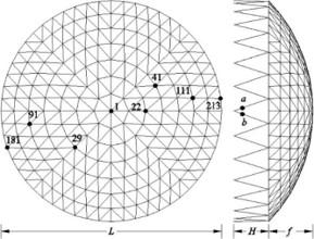
The span and span ratio of the latticed shell are L=50m and f/L=0.2, respectively. The latticed rods are steel pipes of three different sizes (Ф70×4mm, Ф83×4mm and Ф108×4mm), and are supported by steel columns with the height of H=8m. The steels are Q235 in grade and ρ=7.85×10³kg/m3 in density.
Based on the Timoshenko beam theory, each rod was modelled with the BEAM188 elements from the library of ANSYS elements, laying the basis for analysis on geometric nonlinearity and material nonlinear effect. The roof load and self-weight of the structure were considered as an equivalent concentrated mass, and simulated as MASS21 elements.
The yield, hardening and damping of the lattice shell structure (Figure 1) were described by the von Mises yield criterion, bilinear kinematic hardening (BKIN), and Reyleigh damping model, respectively. The yield strength fy is 235MPa, Young’s modulus E is 2.1×10⁵MPa, plastic hardening modulus Et is 7.9×10²MPa, and lateral deformation coefficient ν is 0.3.
Figure 1. The finite-element model of the lattice shell structure
2.2 Time-impact load curve
The impact loads can be abstracted as triangular, sinusoidal, rectangular or oscillation pulse [22]. As suggested by Wang et al., a triangular impulse load was applied on the steel column supports of the lattice shell. The load lasts t=15ms and reaches the peak Pmax at t=5ms. Figure 2 shows the time variation of the impact load.
Figure 2. Time-impact load curve
There is little report on the load design for vehicle impact on structures. For example, the General Specifications for Design of Highway Bridges and Culverts (JTG D60-2015) [24] stipulates that the standard load of vehicle impact is 1,000kN in the driving direction, and 500kN in the direction perpendicular to the driving direction; the impact loads in the two directions should not be considered at the same time. But these Specifications do not provide the load design formula for vehicle impact on structures.
Currently, the load of vehicle impact on structures is usually designed based on the energy principle or the momentum principle.
(1) Load design based on energy principle
The load design formulas for vehicle impact on structures specified by the European norm [25] and the Code for Design on Railway Bridge and Culvert (TB10002-2017) [26] are respectively expressed as:
$F=v \sqrt{k W}$ (1)
$E=\gamma v \sin \alpha \sqrt{W /\left(C_{1}+C_{2}\right)}$ (2)
where, F is the impact load (kN); v is the vehicle velocity (m/s); W is the vehicle weight (kN); k is the stiffness coefficient (kN/m); γ is the kinetic energy correction factor (s/m1/2); α is the collision angle (°); C1 and C2 are the elastic deformation coefficients of the vehicle and the structure, respectively.
(2) Load design based on momentum principle
The load design formulas for vehicle impact on structures specified by the General Specifications for Design of Highway Bridges and Culverts (JTG D60-2015) [24] can be expressed as:
$F=W v /(g T)$ (3)
The above formulas help to identify the factors affecting the impact load. Eq. (1)-(3) show the influence of vehicle weight and velocity on the magnitude of impact load. Eq. (1)-(2) reflect the effects of vehicle stiffness and structure stiffness on the magnitude of impact load. Besides, the range of the impact load can be approximated by Eq. (2), laying the theoretical basis for the peak impact load Pmax in this research.
where, g is the acceleration of gravity (s/m2); T is the impact time (s); the other symbols have the same meanings as above.
Before analyzing the dynamic response, it is assumed that one steel column support of the lattice shell structure is impacted by a heavy vehicle at one point (node 260) at the height of 2m, the impact load peaks at 1,000kN, and the steel column supports are of the size Ф152mm×6mm.
Figures 3 and 4 show the deformation of the entire structure and that of the steel column supports, respectively; Figure 5 displays the time variation in displacement at node 260; Figures 6-12 presents the time variation in displacement at each node (nodes 181, 1, 91, 29, 41, 111 and 213 in Figure 1) of the latticed shell.
Figure 3. Global deformation of the lattice shell structure
Figure 4. Deformation of steel column supports
Figure 5. Time-displacement curve of node 260
As shown in Figures 4 and 5, the horizontal displacement of the steel column support at the impact point peaked at 1,378mm at 25ms, and stabilized at 1,130mm at 65ms with a small fluctuation of 20mm. The deformation mode of the steel column support takes the half sinusoidal form. The peak plastic strain was observed as 0.272, indicating that the steel column support is broken.
Figure 6. Time-displacement curve of node 181
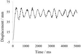
Node 213 and node 181 both fall on the outer ring that joins up the latticed shell and the steel column supports. The former is close to the impacted steel column support and the latter is far away from that support. As shown in Figures 6 and 12, both nodes reached the peak displacement at the first vibration. The horizontal displacement of node 213 peaked at 68mm at 242ms, slightly larger than that (63mm at 238ms) of node 181. The vibration amplitudes of nodes 213 and 181 were initially 27mm and 22mm, respectively, and then gradually decreased.
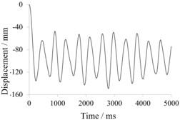
As shown in Figures 7-11, none of the nodes that entirely fall on the latticed shell reached the peak displacement at the first vibration, but after several vibration cycles. The vibration amplitudes of these nodes were much greater than those of nodes 213 and 181. Moreover, nodes 111 and 91, which are on the same ring, had similar vertical displacements (105mm vs. 101mm) and similar vibration amplitudes (40mm); nodes 41 and 29, also on the same ring, had similar vertical displacements (153mm vs. 146mm) and similar vibration amplitudes (84mm). Hence, the nodes in the same ring bear resemblance in vibration laws: these nodes tend to have similar amplitude, trend and equilibrium position of vibration.
Figure 7. Time-displacement curve of node 1
Figure 8. Time-displacement curve of node 91
Figure 9. Time-displacement curve of node 29
Figure 10. Time-displacement curve of node 41
Figure 11. Time-displacement curve of node 111
Figure 12. Time-displacement curve of node 213
The above analysis shows that, except for the impacted steel column support and the members on the outer ring, the members on the other rings are in an elastic state. Overall, the working performance of the latticed shell structure is not damaged by the impact load, that is, the structure still enjoys satisfactory strength and stability.
To realize safe and normal operation, the latticed shell structure must satisfy requirements on strength, stability and stiffness. Based on engineering designs, the allowable deflection of a single-layer latticed shell structure can be empirically defined as 1/400 of the span [20], i.e. 125mm.
Obviously, the latticed shell structure failed to meet the allowable deflection. The peak vertical displacements of nodes 29, 41 and 22, which are in the center of the structure, surpassed the allowable deflection by 16.8%, 22.4% and 48.8%, respectively. The large deflections will affect and even damage structural members like roof slabs and purlins, as well as the working conditions of internal facilities (e.g. suspension equipment). As a result, the latticed shell structure could no longer operate normally.
In addition, the peak vertical displacements of the nodes connecting the outer ring and the impacted support exceeded the allowable deflection, causing irreversible damage to the latticed shell structure.
4.1 Influence of peak impact load
To analyze the influence of peak impact load, it is assumed that one steel column support of the lattice shell structure is impacted by a heavy vehicle at one point at the height of 2m, and the steel column supports are of the size Ф152mm×6mm. Meanwhile, the peak impact load was set to 1,000, 1,500 and 2,000kN in turn.
Figures 13 and 14 present the time variation in displacement and the deformation of the impacted steel column support, respectively. Figures 15-17 provide the time-displacement curves of nodes 1, 41 and 181, which are on the latticed shell at different distances from the impact point, respectively. Figure 18 shows the relationship between maximum displacement and peak impact loads.
Figure 13. Time-displacement curves of node 260
Figure 14. Deformation of the impacted steel column support
As shown in Figure 13, the horizontal displacement of the steel column support at the impact point reached the peak at the first vibration, and gradually returned to the equilibrium position, with a small fluctuation. As shown in Figure 14, the impacted support suffered from anomalous plastic deformation under peak impact loads of 1,500 and 2,000kN. The main reason for the deformation is as follows: Under the large impact load(s), the steel column support has a large plastic dissipation, causing local oscillation of the impact point; meanwhile, the plastic deformation remains at the original position. As a result, the upper half of the support deformed in a half sinusoidal form under 1,500kN (Figure 14b) and a complete sinusoidal form opposite to the impact direction under 2,000kN (Figure 14c). The results indicate that plastic collapse has occurred in the impacted support.
Figure 15. Time-displacement curves of node 1
Figure 16. Time-displacement curves of node 41
Figure 17. Time-displacement curves of node 181
Figure 18. The relationship between maximum displacement and peak impact loads
As shown in Figures 15-18, with the growth in peak impact load, the maximum vertical displacement of the upper latticed shell had a small linear increment. In our assumptions, the impact comes from a heavy vehicle, and the peak impact load occurs when the vehicle is overloaded. According to the general value of plastic failure strain in engineering, the impacted steel column support must have been broken or almost broken. Since the impacted support has strong plastic dissipation, only a limited amount of energy could be transferred from the support to the latticed shell. Thus, none of nodes 1, 41 and 181 had a marked amplitude increase.
4.2 Influence of lateral stiffness of support
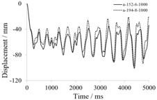
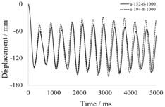
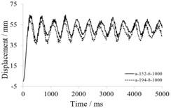
To analyze the influence of lateral stiffness of support, it is assumed that one steel column support of the lattice shell structure is impacted by a heavy vehicle at one point at the height of 2m, and the impact load peaks at 1,000kN. Meanwhile, the size of steel column supports was set to Ф152mm×6mm and Ф194mm×8mm, respectively. That is, the impacted support has two different lateral stiffness.
Figure 19 displays the time-displacement curves of the steel column support with different lateral stiffness at the impact point. Figures 20-22 provide the time-displacement curves of nodes 1, 41 and 181, which are on the latticed shell at different distances from the impact point, respectively, under the two different lateral stiffness of the impacted support.
Figure 19. Time-displacement curves of node 260
As shown in Figure 19, the horizontal displacements of the impact point reached the peak of 1,378mm at 26ms and that of 839mm at 48.2ms, respectively, under the two different lateral stiffness of the impacted support. After that, the horizontal displacement reduced to 1,048mm with a small amplitude fluctuation (30mm) after 62ms, when the lateral stiffness was smaller; the horizontal displacement fluctuated near the maximum value, when the lateral stiffness was larger.
Figure 20. Time-displacement curves of node 1
Figure 21. Time-displacement curves of node 41
Figure 22. Time-displacement curves of node 181
As shown in Figures 20-22, with the growth in lateral stiffness of the impacted support, the maximum displacement at the impact point increased, that at the center of the latticed shell remained constant, and that far away from the impact point decreased. The different trends are the result of the growing lateral stiffness, which enhances the bearing capacity and absorbs more impact energy. For the node close to the impact point, the maximum displacement increases as more energy is absorbed. For the node far away from the impact point, the maximum displacement is mainly affected by the enhanced bearing capacity.
Overall, the displacement increment is outshined by displacement decrement. Thus, the greater the lateral stiffness of steel column supports, the larger the impact resistance of the overall structure.
4.3 Influence of the number of impact points
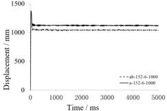
To analyze the influence of the number of impact points, it is assumed that one steel column support of the lattice shell structure is impacted by a heavy vehicle at two points (a and b) at the height of 2m, the impact load peaks at 1,000kN, and the size of the steel column supports was set to Ф152mm×6mm.
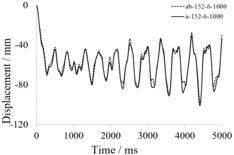
Figure 23 compares the time-displacement curves of the impacted support under one-point impact and two-point impact. Figures 24-26 present the time-displacement curves of nodes 1, 41 and 181 under one-point impact and two-point impact, respectively.
Figure 23. Time-displacement curves of node 260
As shown in Figure 23, the horizontal displacements of the impacted steel column support were 1,378mm and 1,377mm at 26ms, respectively, under one-point impact and two-point impact. When the vibration equilibrium was restored at 62ms, the horizontal displacements were 1,130mm and 1,048mm, respectively, under one-point impact and two-point impact. However, the vibration amplitudes were both about 30mm under the two impact modes.
Figure 24. Time-displacement curves of node 1
Figure 25. Time-displacement curves of node 41
Figure 26. Time-displacement curves of node 181
As shown in Figures 24-26, nodes 1, 41 and 181 had similar amplitude, trend and equilibrium position of vibration, under one-point impact and two-point impact. The displacements of the impacted support and the nodes on the latticed shell both decreased slightly, when the one-point impact was replaced with two-point impact.
(1) During impact response, the nodes in the same ring of the latticed shell tend to have similar amplitude, trend and equilibrium position of vibration. The nodes in the middle ring have much greater vibration equilibrium position and vibration amplitude than the central node or those in the outer rings. The vibration amplitude of the outer ring nodes appears earlier than those in the middle ring, which in turn occurs earlier than those in the central node.
(2) The steel column support broke under the impact load of the heavy vehicle. The greater the lateral stiffness of the support, the better the impact resistance of the overall structure. Before the support reaches the ultimate strain, the growing peak impact load has a great impact on the maximum vertical displacement of the latticed shell structure. But the impact decreases after the support has reached the ultimate strain.
(3) Under the impact load of the heavy vehicle, the peak vertical displacements of the nodes connecting the outer ring and the impacted support exceeded the allowable deflection, causing irreversible damage to the latticed shell structure. In this case, the latticed shell structure needs to be reinforced (e.g. replacing some of the rods) before use.
(4) Except for the impacted support and rods connected to the support, the entire latticed shell structure is basically in an elastic state. Overall, the working performance of the latticed shell structure is not damaged by the impact load, that is, the structure still enjoys satisfactory strength and stability, with no dynamic instability. Hence, the latticed shell structure boats good working performance under impact load.
The author(s) disclosed receipt of the following financial support for the research, authorship, and/or publication of this article: This work was supported by Natural Fund of Hebei Province (No. E2018204019), Guide Project Fund of Hebei Provincial Education Department (No. ZC2016142) and Science and Engineering Fund of Hebei Agricultural University (No. LG201713 and LG201714).
[1] Wierzbicki, T., Teng, X. (2003). How the airplane wing cut through the exterior columns of the World Trade Center. International Journal of Impact Engineering, 28(6): 601-625. https://doi.org/10.1016/S0734-743X(02)00106-9
[2] Karim, M.R., Fatt, M.S. (2005). Impact of the boeing 767 aircraft into the world trade center. Journal of Engineering Mechanics, 131(10): 1066-1072. https://doi.org/10.1061/(ASCE)0733-9399(2005)131:10(1066)
[3] Yamashita, T., Kato, S. (2001). Elastic buckling characteristics of two-way grid shells of single layer and its application in design to evaluate the non-linear behavior and ultimate strength. Journal of Constructional Steel Research, 57(12): 1289-1308. https://doi.org/10.1016/S0143-974X(01)00024-4
[4] Fan, F., Shen, S.Z., Parke, G. A. R. (2005). Study of the dynamic strength of reticulated domes under severe earthquake loading. International Journal of Space Structures, 20(4): 235-244. https://doi.org/10.1260/026635105775870251
[5] Yanagisawa, T., Kato, S. (2017). Reliability analysis of buckling strength of single layer reticulated domes under severe earthquakes. Journal of the International Association for Shell and Spatial Structures, 58(3): 189-205. https://doi.org/10.20898/j.iass.2017.193.840
[6] Taniguchi, Y., Matsui, T., Yoshinaka, S. (2016). Comparison study of elasto plastic behavior on static and dynamic responses for single layer lattice domes. In Proceedings of IASS Annual Symposia, 2016(4): 1-9.
[7] Sun, J., Li, H., Nooshin, H., Parke, G. A. (2014). Dynamic stability behaviour of lattice domes with substructures. International Journal of Space Structures, 29(1): 1-7. https://doi.org/10.1260/0266-3511.29.1.1
[8] Yang, D., Yun, C., Wu, J., Yao, Y. (2018). Seismic response and failure mechanism of single-layer latticed domes with steel columns and braces as substructures. Thin-Walled Structures, 124: 458-467. https://doi.org/10.1016/j.tws.2017.12.038
[9] Riera, J.D. (1980). A critical reappraisal of nuclear power plant safety against accidental aircraft impact. Nuclear Engineering and Design, 57(1): 193-206. https://doi.org/10.1016/0029-5493(80)90233-2
[10] Karagiozova, D., Alves, M. (2004). Transition from progressive buckling to global bending of circular shells under axial impact-Part I: Experimental and numerical observations. International Journal of Solids and Structures, 41(5-6): 1565-1580. https://doi.org/10.1016/j.ijsolstr.2003.10.005
[11] Karagiozova, D., Alves, M. (2004). Transition from progressive buckling to global bending of circular shells under axial impact-Part II: Theoretical analysis. International Journal of Solids and Structures, 41(5-6): 1581-1604. https://doi.org/10.1016/j.ijsolstr.2003.10.006
[12] Karagiozova, D., Jones, N. (2000). Dynamic elastic-plastic buckling of circular cylindrical shells under axial impact. International Journal of Solids and Structures, 37(14): 2005-2034. https://doi.org/10.1016/S0020-7683(98)00343-6
[13] Nagel, G.M., Thambiratnam, D.P. (2004). A numerical study on the impact response and energy absorption of tapered thin walled tubes. International Journal of Mechanical Sciences, 46(2): 201-216. https://doi.org/10.1016/j.ijmecsci.2004.03.006
[14] Nagel, G.M., Thambiratnam, D.P. (2004). Dynamic simulation and energy absorption of tapered tubes under impact loading. International Journal of Crashworthiness, 9(4): 389-399. https://doi.org/10.1533/ijcr.2004.0298
[15] Adachi, T., Tanaka, T., Sastranegara, A., Yamaji, A., Kim, S.K., Yang, I.Y. (2004). Effect of transverse impact on buckling behavior of a column under static axial compressive force. International Journal of Impact Engineering, 30(5): 465-475. https://doi.org/10.1016/j.ijimpeng.2003.08.005
[16] Li, H.W., Guo, K., Wei, J.W., Qin, D.Q. (2006). The dynamic response of a single-layer reticulated shell to drop hammer impact. Explosion and Shock Waves, 26(1): 39-45. https://doi.org/10.3321/j.issn:1001-1455.2006.01.007
[17] Fan, F., Wang, D., Zhi, X., Shen, S. (2010). Failure modes of reticulated domes subjected to impact and the judgment. Thin-Walled Structures, 48(2): 143-149. https://doi.org/10.1016/j.tws.2009.08.005
[18] Wang, X.L., Ma, X.T. (2014). Dynamic response analysis of single-layer spherical reticulated shell under horizontal impact load. Advanced Materials Research, 838: 342-346. https://doi.org/10.4028/www.scientific.net/AMR.838-841.342
[19] GB50017-2003 (2003). steel structure design specification. Beijing: China Planning Press.
[20] JGJ7-2010 (2010). Technical specification for space grid structure. Beijing: China Building Industry Press.
[21] Song, T., Lü, L. (2011). Effects of explosive loads on progressive collapse performance of multi-storey steel frames. Dongnan Daxue Xuebao (Ziran Kexue Ban)/Journal of Southeast University (Natural Science Edition), 41(6): 1247-1252. https://doi.org/10.3969/j.issn.1001-0505.2011.06.023
[22] He, Y., Zhou, X., Liu, X. (2015). Dynamic response of the high-rise steel tridimensional parking structure for vertical impact excitation of the lifting system. The Structural Design of Tall and Special Buildings, 24(12): 779-796. https://doi.org/10.1002/tal.1211
[23] Wang, X.G., Su, Y.P., Ge, N., Wang, C.M. (2011). Research on a simplified reinforced concrete frame column model subjected to lateral impact load. Journal of Guangxi University (Natural Science Edition), 36(1): 15-20. https://doi.org/10.3969/j.issn.1001-7445.2011.01.003
[24] Ministry of Transport of the People’s Republic of China. (2004). General specifications for design of highway bridges and culverts.
[25] European Committee for Standardization (CEN). (2003). Actions on structures. Part 2: Traffic loads on bridges. EN 1991-2 Eurocode 1.
[26] TB1002.1-2005 (2005). Basic code for design of railway bridges and culverts. Beijing: China Railway Publishing House.