Mustafa B. Al-hadithi*![]() | Saad M. Jalil
| Saad M. Jalil![]() | Amjad B. Abdulghafour
| Amjad B. Abdulghafour![]()
© 2023 IIETA. This article is published by IIETA and is licensed under the CC BY 4.0 license (http://creativecommons.org/licenses/by/4.0/).
OPEN ACCESS
This work studies the thermal performance of a novel Spiral Solar Collector SSC experimentally with a mass flow rate ranged from 0.078 to 0.025 kg/s in an open system. A spiral-shaped tube of 13.5 m length, 0.01434 m diameter. The spiral shape is formed from six turns with an 11 cm gap distance between each spiral turn that is attached to an absorber plate. A new black paint mixed with a red sand powder is used to paint the mild steel absorber plate. The experiments are carried out in Al Ramadi city- Iraq under clear weather conditions during January and March 2022. Under different mass flow rates, two fluid flow cases are tested in the experiments; open system and close system cases. The proposed SSC represents a new alternative design that has a noticeable effect on thermal efficiency and outlet temperature. The results showed that there is an increase in the fluid outlet temperature with decreasing the mass flow rate. The difference between the experimental and theoretical results for the maximum value of the temperature difference is (17 K), which gave (6%) percentage error. It is found that the maximum temperature difference was 15 K in the open system case for a flow rate of 0.025 kg/s. According to the current findings, the thermal efficiency has increased up to 17% compared with other SSC and 27% related to conventional flat plate collectors.
flat plate solar collector, spiral solar collector, solar water collector efficiency, useful heat gain, experimental investigation
In many countries, industrial growth and living development dramatically increase energy demand. Therefore, a considerable gap between energy demand and energy supply became noticeable. Renewable energy sources are economic and sustainable, it's getting more attention in the world. Most technologist countries and industrial states have included in their programs energy generation from renewable energy sources. Nowadays, solar energy considers the biggest source of energy and receives more attention in the world. This attention is due to the high level of traditional energy that is provided and using clean technologies that do not have any environmental pollution. The Solar Water Heating SWH system converts the thermal energy that is coming from the sun through radiation into thermal energy to the fluid flows inside pipes by conduction and convection. The outlet temperature plays an important role in choosing the appropriate type of SWH collector. Concentrated and flat-plate solar collectors are the main types of SWH used today in the world. The welded pipes to a flat plate are the most collectors configuration that is used in domestic and industrial SWH systems. The circulating water between the collector and storage tank will get the maximum thermal energy storage in a storage tank. The most conventional arrangement of the SWH system depends on fitting the flat plate inside a wooden box covered by transparent glass from the top and insulated from the bottom to reduce heat losses. Due to its low cost, less maintenance requirements, average efficiency, and simple integration with roof surfaces. These types of SWH collectors have been installed on many commercial and residential buildings for heating water and space [1, 2]. Various modifications have been studied to increase the efficiency and thermal performance of the flat plate SWH by changing various input parameters.
Solar energy is collected using a flat-plate collector that is attached at the bottom and consists of a thin absorber plate combined with a tube [3]. The findings demonstrated that the temperature of the flat plate absorber increases because the emitted radiation cannot pass through the glass. Additionally, the water heats up and flows into the storage tank via the thermo-siphon principle. Experimental work and numerical analysis are noted on two types of tube configurations [4]. In comparison to the sine wave absorber tube configuration, the straight absorber tube configuration has a superior capacity for heat transmission. The effectiveness of a solar concrete sand absorbers collector for household hot water heating systems has been studied [5]. Theoretical studies are conducted on different inlet mass flow rates for spiral tubes from (0.006 to 0.01 kg/s), where the average water temperatures of concrete and sand absorber are found (72℃ and 76℃). The comparison of performance between an innovative spiral-shaped solar collector and with traditional (FPSC) is investigated [6]. The following findings for the novel spiral design collector have been documented: the highest improvement in thermal efficiency observed, which is (21.94%) compared to conventional (FPSC) at a mass flow rate (0.026 kg/s) and intensity (1011 W/m2), lesser pressure drop due to the single smooth flow in the tube, and 30% materials can be saved for spiral design with the same area of the collector (FPSC). The thermal efficiency of a spiral-type solar collector has been simulated numerically by Rahi and AbdulKareem [7]. Estimation of the efficiency and temperature have been distributed by ANSYS-Fluent software. Assuming that the flow is steady-state and that the working fluid is water, the 3D transient energy equation was solved. The effects of varying water flow rates, flow directions, and pipe diameters on temperature and thermal efficiency distribution were examined. When comparing anticipated findings with data from the practical test utilizing a spiral-type solar collector model, excellent agreement was found. Thermal efficiency improved by 34.6% when compared to the worst situation, which is when the flow velocity is the same but the entrance port is circumferential. The outlet temperature of the water was calculated using a steady-state numerical simulation using the ANSYS Fluent program [8]. The experimental findings were used to validate the obtained CFD results. They found in their work several heliostat effects on the performance of spiral solar collectors. Also, they found the flow rate increases the average temperature decreases, and the heat transfer rate increases. They observed that due to the formation of vortices in the spiral solar collector, the coefficient of heat transfer increased by 1.44 times that of the straight tube type in (FPSC). Experimental and numerical results of SSC for an open and closed system were obtained by Jawad et al. [9]. With error rates of 11% and 8.8% in the closed and open systems, respectively, it provided a good agreement. The findings indicated that a reduction in mass flow rate causes an increase in outlet temperature and, consequently, an increase in temperature differential. The difference in maximum temperature in the open system was 12.3℃ for the water flow rate of 1 L/min and 25.3℃ in the closed system at the same flow rate.
According to previous literature reviews which are covering theoretical, experimental, and computational works by the researcher. It can be assumed that the design changes were a fundamental strategy to increase the solar collector’s efficiency. The spiral tube solar collector design that is used in the current paper is a novel fabricated spiral tube in terms of the length, number of turns, and the distance between each coil under the weather conditions in the Republic of Iraq. The better information we have is based on the available research literature, it's still undiscovered. The main concern of presenting this work is to provide a highly efficient SSC to the domestic and industrial sectors at a lower price compared to traditional collectors.
Various parameters and efficiencies will be calculated by fundamental mathematical relations. The heat losses, efficiency, and output temperatures are the main parameters of the present work. Also, the overall heat losses coefficient (UL) and thermal efficiency $\eta_c$ of the collector can be calculated.
2.1 Collector heat losses
The heat losses from the collector are an essential part for evaluating its efficiency. Three types of heat losses are considered in the calculation procedures. Losses from the upper, lower, and sides surfaces of the collectors are important factors in determining the collector's performance. Hence, the total heat losses from the collector can be expressed as follows [10].
$\mathrm{Q}_{\text {loss }}=\mathrm{U}_{\mathrm{L}} \mathrm{A}_{\mathrm{c}}\left(\mathrm{T}_{\mathrm{c}}-\mathrm{T}_{\mathrm{a}}\right)$ (1)
The overall heat loss coefficient (UL) can be calculated [11] as follows
$\mathrm{U}_{\mathrm{L}}=\mathrm{U}_{\mathrm{t}}+\mathrm{U}_{\mathrm{b}}+\mathrm{U}_{\mathrm{e}}$ (2)
The energy losses through the upper surface by convection between parallel plates and the radiation across them as in the study of Iordanou [12]. Then, the coefficient of heat losses from the upper surface can be formulated as
$\begin{aligned} & U_t =\left\{\frac{N}{\frac{c}{T_p}\left(\frac{T_p-T_a}{N+f}\right)^e}+\frac{1}{h_a}\right\}^{-1} \\ & +\frac{\sigma\left(\mathrm{T}_{\mathrm{p}}+\mathrm{T}_{\mathrm{a}}\right)\left(\mathrm{T}_{\mathrm{p}}^2-\mathrm{T}_{\mathrm{a}}^2\right)}{\frac{1}{\epsilon_{\mathrm{p}}+0.00591 * \mathrm{~N} * \mathrm{~h}_{\mathrm{a}}}+\frac{2 \mathrm{~N}+\mathrm{f}-1+0.133 \epsilon_{\mathrm{p}}}{\epsilon_{\mathrm{p}}}-\mathrm{N}} \\ & \end{aligned}$ (3)
$c=520 *\left(1-0.0051 * \beta^2\right)$ for $0<\beta<70^{\circ}$ (4)
$f=(1+0.089*h_a-0.1166*h_a*∈_p )(1+0.07866*N)$ (5)
${h_a}=5.7+3.8 *v$ (6)
The heat loss from the back surface of the collector does not exceed 10% of the heat loss from the front surface. The heat transfer coefficient of the back surface is calculated by using the following formula:
$\mathrm{U}_{\mathrm{b}}=\frac{\mathrm{k}_{\mathrm{b}}}{\mathrm{x}_{\mathrm{b}}}$ (7)
Similarly, the following formula can be used to determine the heat transfer coefficient from collector edges.
$\mathrm{U}_{\mathrm{e}}=\frac{2 * \mathrm{~L}_3\left(\mathrm{~L}_1+\mathrm{L}_2\right) \mathrm{k}_{\mathrm{i}}}{\mathrm{L}_1 \mathrm{~L}_2 \delta_{\mathrm{e}}}$ (8)
2.2 SSC heater efficiency
The SSC system efficiency ($\eta_c$) is the ratio of usable heat gain by a collector to the incident solar radiation on the absorber plate of the collector [3].
$\eta_c=\frac{Q_c}{IA_c}$ (9)
The heat gained by the collector, QC is calculated by multiplying the collector heat removal factor (FR) by the possible total energy gain [10].
$\mathrm{Q}_c=\mathrm{F}_{\mathrm{R}} \mathrm{A}_{\mathrm{c}}\left[\mathrm{I}_{\mathrm{T}}(\alpha \tau)-\mathrm{U}_{\mathrm{L}}\left(\mathrm{T}_{\mathrm{wi}}-\mathrm{T}_{\mathrm{a}}\right)\right]$ (10)
Heat removal factor (FR)
FR= actual useful energy gain / useful energy gain if the complete collection were at fluid inlet temperature.
Mathematically can be expressed as
$\mathrm{F}_{\mathrm{R}}=\frac{\dot{\mathrm{m}} \mathrm{C}_{\mathrm{p}}}{\mathrm{A}_{\mathrm{c}} \mathrm{U}_{\mathrm{L}}}\left[1-\exp \left(-\frac{\mathrm{U}_{\mathrm{L}} \mathrm{A}_{\mathrm{c}}}{\dot{\mathrm{m}} \mathrm{Cp}}\right)\right]$ (11)
The collector plate temperature and water outlet temperature at any time interval can be given as [12]
$\mathrm{T}_{\mathrm{p}}=\mathrm{T}_{\mathrm{wi}}+\frac{\mathrm{Q}_{\mathrm{c}}}{\mathrm{A}_c \mathrm{~F}_{\mathrm{R}} \mathrm{U}_{\mathrm{I}}}\left(1-\mathrm{F}_{\mathrm{R}}\right)$ (12)
$\mathrm{T}_{\mathrm{wo}}=\frac{\mathrm{I}_{\mathrm{T}}(\mathrm{t}) *\left(\alpha \tau \mathrm{A}_{\mathrm{c}}\right)+\left(\mathrm{U}_{\mathrm{L}} * \mathrm{~A}_{\mathrm{c}}\right) *\left(\mathrm{~T}_{\mathrm{p}}-\mathrm{T}_{\mathrm{a}}\right)}{\dot{\mathrm{m}}_{\mathrm{w}} * \mathrm{C}_{\mathrm{pw}}}+\mathrm{T}_{\mathrm{wi}}$ (13)
From Eq. (11) the thermal efficiency of the collector can be reformulated as
$\eta_{\mathrm{c}}=\mathrm{F}_{\mathrm{R}}\left[\alpha * \tau-\frac{\mathrm{U}_{\mathrm{L}}\left(\mathrm{T}_{\mathrm{inl}}-\mathrm{T}_{\mathrm{a}}\right)}{\mathrm{I}_{\mathrm{T}}}\right]$ (14)
In a state where the incidence angle not (90°), a new factor known as incident angle modifier (λθ ) is must be added due to the change in (α*$\tau$) product will arise when (θ) not equal to (90°). For all types of flat plate collectors (kθ) is given as [13]
$\lambda_\theta=1-b_0\left(\frac{1}{\cos \theta}-1\right)-b_1\left(\frac{1}{\cos \theta}-1\right)^2$ (15)
For a single glass collector, we can apply an equation of the first order, (b0=0.1);
$\lambda_\theta=1-b_0\left(\frac{1}{\cos \theta}-1\right)$ (16)
Then, the final form of Eq. (14) can be calculated by using the following Eq. (14)
$\eta_{c \theta}=\mathrm{k}_\theta \mathrm{F}_{\mathrm{R}}\left\lceil\alpha_0 * \tau_0-\frac{\mathrm{U}_{\mathrm{L}}\left(\mathrm{T}_{\mathrm{inl}}-\mathrm{T}_{\mathrm{a}}\right)}{\mathrm{I}_{\mathrm{T}}}\right\rceil$ (17)
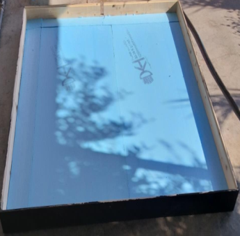
The experimental setup consists of different components that will be described in detail. The container of the solar collector is fabricated using a half-inch thick pressed wood material of 1.37 m long, 1.37 m wide, and 0.14 m height. The wooden container is covered from the inside with foam insulation, with a thickness of (3 cm), used as an insulator for the solar collector. Figure 1 shows the image and dimensions in (cm) of a wooden container. The specifications of the solar collector are listed in Table 1. The absorber plate is painted with special matte black paint mixed with microparticles of a red sand material for maximum absorbing heat due to solar radiation.
Figure 1. Wooden container dimensions of (SSC) heater
Table 1. Specifications of the solar collector
|
Wood dimensions box |
1.37*1.37*0.14 m |
|
Casing |
Wood container/fixed on an iron frame |
|
Aperture area |
1.7689 m2 |
|
Absorbing plate |
(1.33*1.33*0.004 m) iron plate |
|
Tube specification |
Copper, 13.5 m length, 0.01434m inside diameter, 0.771 mm tube thickness, 6 coil number, 11 cm distances between coils |
|
Insulation material |
Foam, 3 cm thickness |
|
Glass cover |
One glass 4 mm thickness |
|
Tilted angle |
47° southward |
|
Storage tank |
Cylindrical insulated shape 80 liters volume |
|
Absorbing material |
Special black coating mixed with red sand powder |
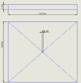
K- type thermocouples are used at the inlet, outlet, absorber plate, and storage tank to measure the temperature of the water absorber plate. Figures 2 and 3 show the experimental rig sketch and the solar collector image, respectively. A solar power meter type (SPM-1116SD) is used to measure the heat flux that incident on the absorber plate as a result of solar irradiation with resolution $\frac{0.1 \mathrm{~W}}{\mathrm{~m}^2}<1000 \frac{\mathrm{W}}{\mathrm{m}^2}$ and $1 \frac{\mathrm{W}}{\mathrm{m}^2} \geq 1000 \mathrm{~W} / \mathrm{m}^2$ .
The thermal performance of the SSC heater was examined experimentally in Ramadi - Iraq, at latitude (33.25ºN) longitude (43.18ºE) in the clear climatic conditions of the province during the cooling months of the year.
Figure 2. Sketch of the experimental rig
3.1 Spiral coil forming
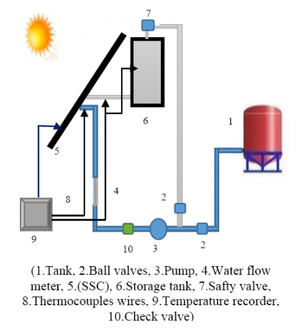
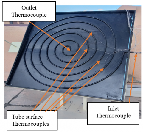
The heat transfer characteristic that can be obtained from a spiral tube heat exchanger is more effective compared with a straight tube heat exchanger under the same working conditions. A straight copper tube of a (14.34 mm) inside diameter (0.771 mm) tube wall thickness (13.5 m) length is bent in the form of a spiral, which forms (6) coils with (11 cm) gap between two successive turns. A spiral coil is fixed on the front mild steel flat plate (133*133*0.4 cm) by multi-brazing points along the spiral tube length. The inlet of working fluid from the circumferential direction of the spiral coil and outlet at the central turn direction of the spiral coil as shown in Figure 3. The temperature measurements are measured in five nodes on a spiral coil. Two k-thermocouples types are used to measure the working fluid at the inlet and outlet with an error of (±0.5℃) observed from standard reader calibrations. Table 2 shows the thermocouple positions along the spiral tube.
Figure 3. Photographic view of the experimental rig
Table 2. Thermocouple positions
|
Thermocouples |
Positions along the coil (m) |
|
Input (water) |
0.0 |
|
Tube Surface-1 |
0.8 |
|
Tube Surface-2 |
4.3 |
|
Tube Surface-3 |
7.2 |
|
Tube Surface-4 |
9.2 |
|
Tube Surface-5 |
11.2 |
|
Output (water) |
13.5 |
|
Plate surface |
5 cm from the outer coil tube |
|
Storage tank |
At (15 cm) from top |
3.2 Test procedure
The experimental procedure was carried out as follows
The thermal performance of SSC was verified theoretically and experimentally under the influence of different water mass flow rates in two cases. The measurements were carried out on eight days from the 25th to the 30th of January and on the 6th and 7th of March 2022. All experiments for each case were done under the same outer weather conditions in terms of beam solar radiation, ambient temperature, wind speed, and humidity, which has an obvious effect on the thermal performance of the SSC.
4.1 Open system
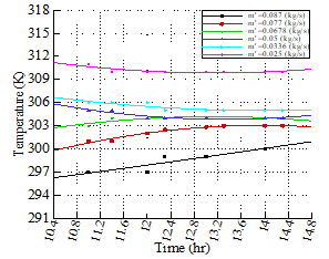
The variation of the outlet temperature with time for the six considered mass flow rates (0.087 to 0.025) kg/s are illustrated in Figure 4. The results were taken every (20 min) of the specified period. The results indicated that the decrease in the mass flow rate leads to an increase in the results every (20 minutes) during the designated time frame. The findings showed that a reduction in mass flow rate causes an increase in the outlet temperature. The maximum average outlet temperature reached (311 K) for a mass flow rate (0.025 kg/s) with an average inlet temperature (290 K). The increase in temperature with the lowest mass flow rate is due to more solar energy being absorbed by water through the tube wall since the water takes more time inside the spiral tube for this level of mass flow rate.
Figure 4. Experimental outlet temperature with time
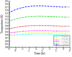
Figure 5. Theoretical outlet temperature with time
Figure 5 describes the behavior of theoretical outlet water temperature with the variation of mass flow rate. Observations indicate that outlet temperature increases with decreasing mass flow rate, this result is very logical from an analytical point of view because the mass flow rate is in the denominator as in Eq. (13). The maximum outlet temperature reaches (328 K) at a mass flow rate (0.025 kg/s).
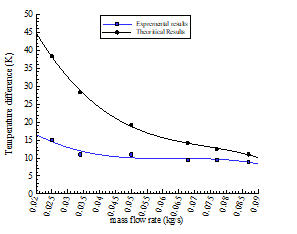
For the open system case, the temperature differences (Two-Twi) are increasing with decreases in mass flow rate for the two solutions results as shown in Figure 6. The results indicated that the maximum temperature difference for the experimental case is (15 K) and (38 K) for theoretical results. These results of the current SSC give a temperature difference more than that obtained in reference [9] which was (12.3 K) under similar weather conditions. In addition, the spiral tube length in their study [9] is longer with an increase of (1.5 m) compared with current work and extra five coil turns. For the daily time from 11:00 to 14:30, the water mass flow rate increases up to (0.075 kg/s). As the water flows through the tube quickly, the findings are not very satisfactory. Additionally, it is not properly catching up with the heat transfer and heating it, it is the main reason why the temperature difference is less than 10 K. for a mass flow rate above (0.075 kg/s).
Figure 6. Water temperature difference with mass flow rate
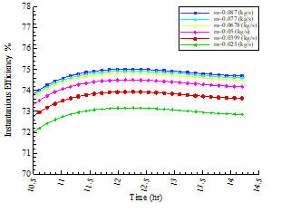
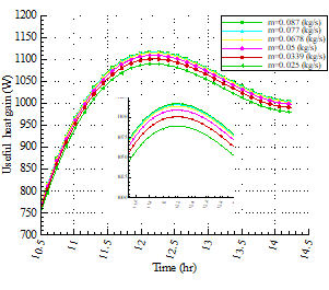
Figure 7 describes the behavior of the instantaneous efficiency of SSC with the variation of mass flow rate. Observed data show that for open system cases, the efficiency increases as the water mass flow rate increases. The maximum collector efficiency reaches more than (73%) between (11:50 to 13:50) for all ranges of mass flow rate. Increasing the intensity of radiation improves thermal efficiency. For maximum instantaneous efficiency, optimal solar beam radiation lies within the range of (975-1040) W/m2. The curves before and after this period decrease in thermal efficiency due to convective and radiative losses are increased compared to useful gain energy from incident solar radiation. By comparing the obtained thermal efficiency from the current SSC with the developed spiral collector in [6] under the same mass flow rate and solar beam radiation, it is found that there is about 12% enhancement in the thermal efficiency, which is 73.16% for current SSC and 61.35% for reference [6]. The useful heat gain by water through SSC is shown in Figure 8, which indicates that the useful heat gain increases with increasing water mass flow rate. This behavior enhances the idea of increases in efficiency as shown in Figure 7. At steady state condition of water flow reaches inside the spiral tube, due to the curvature effect produces centripetal force. This type of centripetal action causes water to flow with induced force on the internal surface of the spiral tube, thus will increase the heat transfer to the water. Furthermore, the increase in water flow rate increases the velocity of water which leads to an increase in the heat transfer coefficient causing more energy to be added to the working fluid. The results were plotted in Figure 8, where the highest values of useful heat gain were recorded in the period (11:00 to 13:00) due to high beam solar radiation in this period. Figures 6-8 indicates that when it is required high outlet temperatures in industrial or residential home applications the mass flow rate must be limited between (0.025 to 0.75 kg/s). But if it is required to store an amount of energy for further use, then the specific mass flow rate is greater than (0.075 kg/s).
Figure 7. Instantaneous efficiency for different mass flow rates
Figure 8. Useful heat gain with time
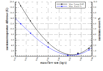
In the case of the open system, as shown in Figure 9, the maximum temperature difference between experimental and theoretical analysis along the period of each mass flow rate is observed. It shows that the maximum difference (18.55 K) at (0.025 kg/s) is increased with decreasing the mass flow rate.
This result is due to the maximum outlet temperatures recorded in this level of mass flow rate, also the results of the highest error value were plotted corresponding to this level of mass flow rate is about (6%), then the values of percentage errors begin to decrease as the mass flow rate increases with acceptable values.
Figure 9. The maximum temperature difference and maximum errors percentage with the mass flow rate
4.2 Closed system
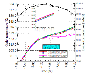
The run of SSC on the (6th and 7th of March 2022) was executed with two different water mass flow rates (0.222 and 0.207) kg/s from (11:00 to 14:50) the results were taken every (5 min) of the specified period. It is clear from Figure 10 that the outlet water temperature of the two rates of the mass flow increased with time as the beam solar radiation increased with time and settle above (900 W/m2) for all periods. Due to this highest value of solar beam, the outlet temperature increases with time during this period. Small temperature differences were observed between theoretical and experimental. For the first level of mass flow rate the maximum difference was (1.24 K) and for the second level was (9.94 K). Moreover, the inlet temperature in the closed system was not constant with time in contrast to the open system. For this reason, the water outlet temperature keeps rising continuously with time for solar beam over (900 W/m2) as observed in Figure 10.
Figure 10. Outlet temperature and solar radiation with time
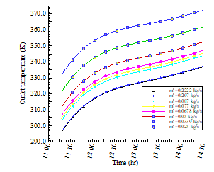
Figure 11 describes the theoretical outlet temperatures with time for variation of water mass flow rate. After demonstrating a good agreement for the two levels of mass flow rate in Figure 10, the simulation of new values can be applied in a closed system case. The behavior of curves is clear from the figure since the outlet temperatures were increased with decreasing mass flow rate, this is due to the same reasons that were mentioned in the case of the open system. Another reason is added to them, which is the increase in the degree of inlet water temperature through the process of circulation in a closed system.
Figure 11. Theoretical outlet temperature for variations mass flow rate
4.3 Validation test
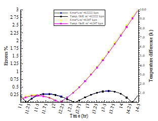
Experimental results are validated theoretically, for the open system case Figure 6 showed that. The maximum error percentage that can be reached for outlet temperature between experimental and theoretical results are not exceeded 6% for all levels of mass flow rate. This result gives a good agreement between the two solutions analysis. Also, this agreement indicates the best assignment for the validation of instrument measurements. Figure 12 shows the maximum error percentage for (0.207 kg/s) mass flow rate in the closed system not exceeding 3% and for (0.2222 kg/s) mass flow rate about (0.35%). The percentage of error generated in the closed system ensures the reliability of the results for the practical and theoretical solutions.
Figure 12. Errors percentage and temperature difference
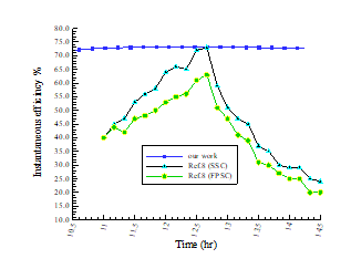
Figure 13 shows the instantaneous efficiency of our work with reference [6] for the same mass flow rate, current work gives superiority over other work but meets at the point where maximum beam solar radiation. Our work gives stable efficiency through the period of maximum beam solar radiation than the other works. Also, the present work agrees with reference [6] about the SSC having more efficiency than the conventional type (FPSC).
Figure 13. Instantaneous efficiency compression
In the present work, the design of an innovative spiral tube solar collector which consists of one copper tube in spiral form with six coils was investigated experimentally and theoretically. Based on the research results analysis the following observations were indicated for SSC. The results showed that the theoretical and experimental findings have a good agreement with an acceptable error percentage not exceeding (6%) for all mass flow rates in open and closed systems. The obtained results proved that when it is required to obtain a relatively high outlet water temperature for direct use or with an auxiliary heating system to be used, it is required to reduce the mass flow rate to less than (0.075 kg/s). Whereas, if it is required to store a quantity of heat to save it in a phase change material or a storage tank for later use, it is suggested to increase the mass flow rate by more than (0.075 kg). Enhancement in thermal efficiency (17%) compared with SSC [6], (27%) to conventional collector design FPSC [6] with the same mass flow rate and beam solar collector.
|
Ac |
Collector area, m2 |
|
Cp |
Specific heat of water, J/kg.K |
|
FR |
Collector heat removal factor |
|
h |
Convective heat transfer coefficient, W/m2.K |
|
IT |
Total beam solar radiation, W/m2 |
|
k |
Thermal conductivity, W/m.K |
|
L1,2,3 |
Length of the wood box, m |
|
$\dot{\mathrm{m}}$ |
mass flow rate, kg/s |
|
N |
Number of glazing |
|
Qu |
Useful energy gain, W |
|
T |
Temperature, K |
|
t |
Time, s |
|
U |
Overall Heat transfer coefficient, W/m2.K |
|
V |
Velocity, m/s |
|
x |
Distance, m |
|
Greek symbols |
|
|
α |
The absorption coefficient of plate |
|
β |
Collector slop |
|
$\delta$ |
Thickness, m |
|
ε |
Emittance of the absorber plate for infrared radiation |
|
η |
Collector efficiency |
|
θ |
Incidence angle |
|
λθ |
incident angle modifier |
|
$\tau$ |
Transmittance of glaze |
|
Subscripts |
|
|
a |
Ambient |
|
b |
Collector back side |
|
c |
Collector |
|
e |
Collector edge |
|
i |
insulation |
|
L |
Overall |
|
p |
Plate |
|
t |
Collector top side |
|
w |
Water |
|
wi |
Water inlet |
|
wo |
Water outlet |
[1] Kumar, R., Rosen, M.A. (2011). A critical review of photovoltaic–thermal solar collectors for air heating. Applied Energy, 88(11): 3603-3614. https://doi.org/10.1016/j.apenergy.2011.04.044
[2] Vaidya, V.B., Walke, P.V., Kriplani, V.M. (2011). Effects of wind shield on performance of solar flat plate collector. Int. J. Appl. Eng. Res., 6: 379-89.
[3] Tang, R., Cheng, Y., Wu, M., Li, Z., Yu, Y. (2010). Experimental and modeling studies on thermosiphon domestic solar water heaters with flat-plate collectors at clear nights. Energy Conversion and Management, 51(12): 2548-2556. https://doi.org/10.1016/j.enconman.2010.04.015
[4] Karanth, V.K., Madhwesh, N., Manjunath, M.S. (2015). Numerical and experimental study of a solar water heater for enhancement in thermal performance. International Journal of Research in Engineering and Technology (IJRET), 4(3): 548-553. https://doi.org/10.15623/ijret.2015.0403091
[5] Edwin, M., Arunachalam, U., Rakesh, R., Srinivas, M.S., Kumar, A.S. (2016). Performance analysis of spiral tube solar water heater using concrete/sand absorbers for domestic use. In 2016 International Conference on Energy Efficient Technologies for Sustainability (ICEETS), pp. 223-227. https://doi.org/10.1109/ICEETS.2016.7582930
[6] Verma, S.K., Sharma, K., Gupta, N.K., Soni, P., Upadhyay, N. (2020). Performance comparison of innovative spiral shaped solar collector design with conventional flat plate solar collector. Energy, 194: 116853. https://doi.org/10.1016/j.energy.2019.116853
[7] Rahi, S.M., AbdulKareem, M.A. (2021). Experimental and numerical investigation of the thermal performance of spiral type solar collector. Journal of Mechanical Engineering Research and Developments, 44(10): 239-250.
[8] Digole, S.P., Karvinkoppa, M., Sanap, S. (2022). Thermal analysis of a spiral solar receiver for a small central receiver system: an experimental and numerical investigation. International Journal of Ambient Energy, 43(1): 1810-1818. https://doi.org/10.1080/01430750.2020.1722744
[9] Jawad, S.A., Rashid, F.L., Ridha, Z.A.A. (2022). Thermal performance of spiral flat plate solar water collector. International Journal of Heat and Technology, 40(1): 183-192. https://doi.org/10.18280/ijht.400122
[10] Selvadhurai, M., Vigneshponmurugan, S., Vijayakumar, R., Dillibabu, V. (2021). Creating a TRNSYS Model of a Spiral Flow Flat Plate Solar Water Heater (SFSWH) and comparingit to a parallel flow flat plate collector: A recent study. Advanced Aspects of Engineering Research 12: 107-123. https://doi.org/10.9734/bpi/aaer/v12/9133D
[11] Duffie, J.A., Beckman, W.A. (1980). Solar Engineering of Thermal Processes. New York: Wiley. pp. 16591. https://doi.org/10.1002/9781118671603
[12] Iordanou, G. (2009). Flat-plate solar collectors for water heating with improved heat transfer for application in climatic conditions of the mediterranean region. Doctoral dissertation, Durham University.
[13] Kalogirou, S.A. (2004). Solar thermal collectors and applications. Progress in Energy and Combustion Science, 30(3): 231-295. https://doi.org/10.1016/j.pecs.2004.02.001