Zhengde Wang![]()
© 2023 IIETA. This article is published by IIETA and is licensed under the CC BY 4.0 license (http://creativecommons.org/licenses/by/4.0/).
OPEN ACCESS
Temperature fluctuation is the primary reason for gradual failure of IGBT (Insulated Gate Bipolar Transistor) module in inverter system, and overall thermal management is an effective way to smooth temperature fluctuation and prolong the service life of IGBT module. Currently there are a series of problems with the module temperature management method of inverter system, including complicated control method, limited adjustment range, slow response, and poor control accuracy, etc. To cope with these matters, this paper aims to study a thermal management strategy for inverter system. At first, this paper built a model for temperature prediction and control of inverter system based on linear time-varying state space, the model measures system state based on estimation and can calculate the control variables with the mutual effect between different variables taken into consideration but without the necessity of system decoupling. Then, this paper proposed a thermal management strategy for inverter system based on predictive control and optimized it further. At last, the validity of the constructed model and the proposed strategy were verified by experimental results.
predictive control, inverter, thermal management strategy
Under the guidance of “emission peaking and carbon neutrality goals”, wind energy, solar energy and other new energy types are developing fast in China these days. Grid-connected inverters play an important role in electricity generation using various energy sources, so they have been widely used in the field of power generation [1-6], and their reliability is very important for stably and reliably merging the generated electricity in to the large power grid [7-11]. IGBT module is one of the most widely used power switching device in various power converters, and its reliability determines the reliability of grid-connected inverters [12-16]. According to existing research findings, temperature fluctuation during operation is the primary reason for gradual failure of IGBT module, and causes for such temperature fluctuation include the fundamental frequency junction temperature fluctuation caused by sinusoidal changes of network side current, and the low frequency junction temperature fluctuation caused by power fluctuation of system [17-23]. This also means that the non-stable operating state of new energy source power generation system will accelerate the aging of IGBT module, thereby shortening the service life of grid-connected inverters, and the thermal management of inverter system is an effective way to smooth junction temperature fluctuation of IGBT module and prolong its service life.
Mistry et al. [24] proposed a compact-style thermal management solution for high power traction inverters, the scheme they designed made use of a stacked cooling system which can extract heat from the two largest heat sources in the power inverter, and the uniform coolant flow can ensure minimal coolant temperature gradient across the switching devices in the power module and the capacitor cells. Their design could maintain a uniform junction temperature in capacitor cells and switching devices, and its validity was then verified by computational fluid dynamics. Cheli and Carcasci [25] developed an on-field diagnostic algorithm for thermal management system of solar field central inverter. They simulated four faults including heat exchanger fouling and cold plate blockage, and examined changes in the maximum junction temperature of electronic components to assess and analyze the impact of faults on the performance of thermal management system in power plant. Guirguis et al. [26] designed a portable high-efficiency single-phase power inverter with a power of 2kW and a volume of 29 in3 that can produce a power density of 69 W/in3. Their work proposed an efficient thermal management and cooling concept to reduce hot spots by distributing the heat more uniformly inside the inverter's enclosure and quickly removing it out of the system. Chang et al. [27] researched a newly developed dual bi-directional IGBT-based inverter combining with autonomous microgrid system with particular attention on thermal management and performance evaluation under various operating conditions, and experimented on locally enhanced heat transfer approach such as oblique orientation and heat dissipating materials. The studied inverter system was initially packaged by a galvanized steel plate sized 62×48×18cm and the switching power was set within the range of 0.5-3kW. The adoption of heat dissipating material in either paste or film form exhibited flexibility tailoring heat transfer performance locally. Experiments of heat dissipating film with various hot spot scenarios indicated that the temperature difference can be reduced as much as 13.1 and 15.4℃ respectively with facilitation of one- and two-layers of heat dissipating film.
After carefully reviewing relevant literatures, it’s found that existing module temperature management methods of inverter system generally have a few problems such as complicated control method, limited adjustment range, slow response, and poor control accuracy, so looking for a junction temperature suppression method of inverter switching devices with simple control, wide range, high precision, and rapid response is a meaningful work, in view of these matters, this paper aims to study a thermal management strategy for inverter system based on predictive control. In the second chapter, this paper built a model for temperature prediction and control of inverter system based on linear time-varying state space, the model measures system state based on estimation and can calculate the control variables with the mutual effect between different variables taken into consideration but without the necessity of system decoupling. In the third chapter, this paper proposed a thermal management strategy for inverter system based on predictive control and optimized it further. At last, the validity of the constructed model and the proposed strategy were verified by experimental results.
Compared with other control methods, predictive control has a few merits such as stable and active control, high accuracy, applicable to multi-input/multi-output systems, and low difficulty in calculation, etc. By applying it to inverter systems, we can measure system state based on estimation and calculate the variables with their mutual effect taken into consideration but without the necessity of system decoupling. Then, this paper modeled the predictive temperature control of inverter system based on linear time-varying state space, laying a basis for the proposal of the thermal management strategy of inverter system based on predictive control.
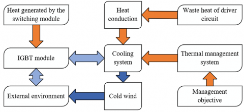
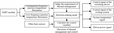
Based on the actual operating conditions of inverter system, in this paper, an assumption was made for the heat transfer model of inverter system, as shown in Figure 1, it’s assumed that there is no heat exchange between IGBT module, driver module, protection module and other components in each sub-system of the thermal management system. Based on this assumption, a temperature prediction model of inverter system was established. Figure 2 gives the structure of thermal management and control strategy for inverter system. Combining with the understanding of thermal management and control strategy of inverter system, the fundamental frequency junction temperature fluctuation of IGBT module, the low frequency junction temperature fluctuation of IGBT module, and the temperature fluctuation of other modules were taken as state variables of the system, and the output power of new energy power generation system was taken as the input of the control system. In the meantime, measurable input disturbances such as power generation environment (lighting, wind) changes and ambient temperature were set.
Figure 1. Heat transfer model of inverter system
Figure 2. Structure of thermal management control strategy for inverter system
The temperature of inverter system, the heat dissipation temperature of cooling system, and the temperature of heat source could be expressed in differential equations as:
${{D}_{Y}}\frac{d{{O}_{Y}}}{do}=\frac{{{O}_{K}}-{{O}_{Y}}}{{{S}_{Y-K}}}+\frac{{{O}_{X}}+{{O}_{Y}}}{{{S}_{Y-X}}}+{{W}_{Y}}$ (1)
${{D}_{K}}\frac{d{{O}_{K}}}{do}=\frac{{{O}_{Y}}-{{O}_{K}}}{{{S}_{Y-K}}}+\frac{{{O}_{PTC}}+{{O}_{K}}}{{{S}_{PTC-K}}}+{{W}_{PHE}}$ (2)
${{D}_{PTC}}\frac{d{{O}_{PTC}}}{do}=\frac{{{O}_{K}}-{{O}_{PTC}}}{{{S}_{PTC-K}}}+{{W}_{_{PTC}}}$ (3)
The following formula gives the state space form of above equations:
$\dot{A}=XA+{{Y}_{v}}v+{{Y}_{q}}q$ (4)
$B=DA$ (5)
where,
$X=\left[\begin{array}{ccc}\frac{-1}{D_Y R_{Y-K}}+\frac{-1}{D_Y S_{Y-X}} & \frac{-1}{D_Y S_{Y-K}} & 0 \\ \frac{-1}{D_K S_{Y-K}} & \frac{-1}{D_K S_{Y-K}}+\frac{-1}{D_K S_{P T C-K}} & \frac{1}{D_K S_{P T C-K}} \\ 0 & \frac{-1}{D_{P T C} S_{P T C-K}} & \frac{-1}{D_{P T C} S_{P T C-K}}\end{array}\right]$,
$Y_v=\left[\begin{array}{l}0 \\ 0 \\ \frac{1}{D_{P T C}}\end{array}\right], D=\left[\begin{array}{lll}1 & 0 & 0\end{array}\right]$,
$Y_q=\left[\begin{array}{ccc}\frac{1}{D_Y S_{Y-X}} & \frac{1}{D_Y} & 0 \\ 0 & 0 & \frac{1}{D_K} \\ 0 & 0 & 0\end{array}\right], A=\left[\begin{array}{l}O_Y \\ O_K \\ O_{P T C}\end{array}\right]$,
$v=\left[W_{P T C}\right], q=\left[\begin{array}{l}O_X \\ W_Y \\ W_{P H E}\end{array}\right]$ (6)
By discretizing Formulas 4 and 5, the temperature prediction model of inverter system could be attained, then the temperature prediction controller was configured in MATLAB, the following formulas describe the model after discretization:
$A(l+1)=\bar{X} A(l)+\bar{Y}_v v(l)+\bar{Y}_q q(l)$ (7)
$B\left( l \right)=DA\left( l \right)$ (8)
where,
$\bar{X}={{p}^{Xo}}$ (9)
$\bar{Y}=\int_{0}^{o}{{{p}^{X\phi }}d\phi {{Y}_{v}}}$ (10)
$\bar{P}=\int_{0}^{o}{{{p}^{X\phi }}d\phi {{Y}_{q}}}$ (11)
Since the properties of heat transfer medium between components of the inverter system and the thermal conductivity of each component would change under different temperature conditions, elements in three matrices shown in above formulas would vary with time during the operating process of the inverter system. In order to update elements in the three matrices at each simulation step, a linear time-varying state space calculation module was programmed in MATLAB/Simulink to avoid model mismatch caused by changes in the temperature of each component of the inverter system.
Following formulas give the state space of the final temperature prediction model of inverter system:
$A\left( l+1 \right)=\bar{X}\left( l \right)A\left( l \right)+{{\bar{Y}}_{v}}v\left( l \right)+{{\bar{Y}}_{q}}\left( l \right)q\left( l \right)$ (12)
$B\left( l \right)=DA\left( l \right)$ (13)
Assuming: Me represents prediction time domain, Md represents control time domain, and they satisfy Me≥Md, then the formula for calculating the predictive output of the prediction model is:
${{\hat{B}}_{Me}}\left( l+1|l \right)={{R}_{a}}A\left( l \right)+{{R}_{v}}V\left( l \right)+{{R}_{q}}Q\left( l \right)+\Gamma p\left( l \right)$ (14)
where,
$\hat{B}_{M e}=\left[\begin{array}{c}\hat{b}(l+1 \mid l) \\ \vdots \\ \hat{b}\left(l+M_e \mid l\right)\end{array}\right], S_x=\left[\begin{array}{cc}D \bar{X} & D \bar{Y}_u \\ D \bar{X}^2 & D \bar{Y}_v+D \bar{X} \bar{Y}_v \\ \vdots & \vdots \\ D \bar{X}^{M_e} & \sum_{f=0}^{M_e-1} D \bar{X}^h \bar{Y}_v\end{array}\right], R_v=\left[\begin{array}{cccc}D \bar{Y}_v & 0 & \cdots & 0 \\ D \bar{X} \bar{Y}_v+D \bar{Y}_v & D \bar{Y}_v & & 0 \\ \vdots & \vdots & & \vdots \\ \sum_{f=0}^{N_e-1} D \bar{X}^f \bar{Y}_w & \sum_{f=0}^{M_e-2} D \bar{X}^f \bar{Y}_v & \cdots & D \bar{Y}_v\end{array}\right], \Lambda=\left[\begin{array}{l}D K \\ D \bar{X} K \\ \vdots D \bar{X}^{M_e} K\end{array}\right]$,
$V(l+i-1 \mid l)=\left[\begin{array}{l}v(l \mid l) \\ v(l+1 \mid l) \\ \vdots \\ v\left(l+M_d-1 \mid l\right)\end{array}\right], Q(l+e \mid l)=\left[\begin{array}{l}q(l \mid l) \\ q(l+1 \mid l) \\ \vdots \\ q\left(l+M_e-1 \mid l\right)\end{array}\right]$ (15)
Assuming: K represents the error gain matrix in temperature predictor of the inverter system, then K could be solved based on the Riccati equation:
$K=\left[\begin{array}{cc}\left(\bar{X} E D^T\right)\left(D E D^T\right)^{-1} & 0 \\ 0 & 0\end{array}\right]$ (16)
Assuming: An(l) represents the actually measured value of system state at time moment l; A^(l|l-1) represents the system state of time moment l predicted at time moment l-1; pa(l|l-1) represents the prediction error of system state, then there are:
$E=\underset{l\to \infty }{\mathop{\lim }}\,P\left( {{p}_{a}}\left( l|l-1 \right){{p}_{a}}{{\left( l|l-1 \right)}^{T}} \right)$ (17)
${{p}_{a}}\left( l|l-1 \right)={{A}_{n}}\left( l \right)-\hat{A}\left( l|l-1 \right)$ (18)
In this part, the paper proposes a thermal management control strategy of inverter system based on predictive control and optimizes it further.
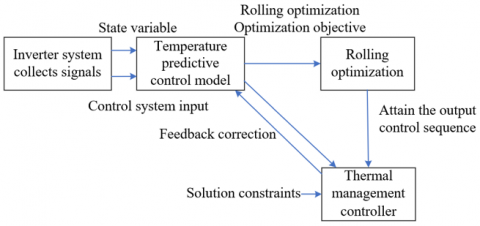
Figure 3. Thermal management and control idea of inverter system
Figure 3 shows the idea of thermal management and control of inverter system. Model temperature prediction, rolling optimization, and feedback correction are three main features of thermal management and control of inverter system based on predictive control. Through rolling optimization, the strategy can give the optimal control sequence of period [l+1,l+t] at time moment l so that the cost function of the sequence is minimized, thereby realizing the optimization of the prediction of control sequence of future time period t made based on the state of current time moment. Through feedback correction, after attaining the optimal control sequence [v(l+1|l),v(l+2|l),...,v(l+o|l)] at time moment l, v(l+1|l) could be taken as the only control input to attain the system state at time moment l+1, in this way, the optimization of the optimal control quantity based on actual system state output could be realized.
The prediction model adopted here is a state space model simplified based on the model constructed in previous section. Assuming: A(l+i|l) represents the estimated value of the state matrix of time moment l+i given by the prediction model at time moment l; V(l+i-1|l) represents the control quantity of optimal control sequence of time moment l+i-1 solved at time moment l; U(l+i-1|l) represents the future disturbance value of time moment l+i-1 input into the system model at time moment l; X, Yv, and Yu represent parameter matrices at current time moment; B(l+i|l) represents the estimated value of system output at time moment l+i given by the model at time moment l; D represents the matrix of coefficients between future state quantities and the output quantities; e represents prediction time domain of the control system; [A(l+1|l),A(l+2|l),...,A(l+e|l)] represent state quantities to be estimated, d represents the control time domain, the control time domain must not be larger than the prediction time domain, then [V(e-d+k|l), V(e-d+2|l),...,V(l+e|l)]=0, and the matrix was completed and can be written as:
$A\left( l+i|l \right)=XA\left( l+i-1|l \right)+{{Y}_{v}}V\left( l+i-1|l \right)+{{Y}_{u}}U\left( l+i-1|l \right)$ (19)
$B\left( l+i|l \right)=DA\left( l+i|l \right)$ (20)
A rolling optimization objective formula was set and introduced to solve above formulas to attain the output control sequence. Assuming: mb and mv respectively represent the number of controlled objects and the number of control variables; qiju represents the weight of the i-th output value of the j-th variable of prediction value B of the controller at time moment kl; qijv represents the weight of the i-th output value of the j-th variable of control quantity output V of the controller; qijΔv represents the weight of change rate of the i-th output value of the j-th variable of control quantity output V of the controller; Cl represents the output value of rolling optimization; d and e respectively represent the control time domain and the prediction time domain of the controller; then the cost equation of the thermal management controller of inverter system at time moment k was solved as follows:
$J\left( {{C}_{l}} \right)={{J}_{b}}\left( {{C}_{l}} \right)+{{J}_{v}}\left( {{C}_{l}} \right)+{{J}_{\Delta v}}\left( {{C}_{l}} \right)$ (21)
${{J}_{b}}\left( {{Z}_{l}} \right)={{\sum\nolimits_{j=1}^{{{m}_{b}}}{\sum\nolimits_{i=1}^{e}{\left\{ q_{i,j}^{b}\left[ {{S}_{j}}\left( l+i|l \right)-B\left( l+i|l \right) \right] \right\}}}}^{2}}$ (22)
${{J}_{v}}\left( {{C}_{l}} \right)={{\sum\nolimits_{j=1}^{{{m}_{v}}}{\sum\nolimits_{i=1}^{d}{\left\{ q_{i,j}^{v}\left[ {{V}_{j}}\left( l+i|l \right) \right] \right\}}}}^{2}}$ (23)
${{J}_{\Delta v}}\left( {{Z}_{l}} \right)={{\sum\nolimits_{j=1}^{{{m}_{v}}}{\sum\nolimits_{i=1}^{d}{\left\{ q_{i,j}^{\Delta v}\left[ {{V}_{j}}\left( l+i|l \right)-{{V}_{j}}\left( l+i-1|l \right) \right] \right\}}}}^{2}}$ (24)
According to above formula, cost function J(Cl) has three parts: Jb(Cl), Jv(Cl), and Jb(Cl). The role of Jb(Cl) is to ensure that the system output value B(l+i|l) of time moment l+i given by model at time moment l approaches the reference value S(l+i|l) as much as possible; the role of Jv(Cl) is to ensure the control sequence is as small as possible, so as to save the energy consumption of the cooling system; the role of JΔv(Cl) is to make the control variable change as small as possible, so as to ensure smooth operation of the thermal management and control process of the entire inverter system.
The objective of rolling optimization introduced here is given by the following formula, that is, to ensure the value of cost function is minimum.
$\min \left[ J\left( {{C}_{l}} \right) \right]$ (25)
Based on the objective of rolling optimization, the solution constraints of optimal control sequence control quantity Cl can be set:
${{V}_{\min }}\le V\left( l+i|l \right)\le {{V}_{\max }}$ (26)
${{B}_{\min }}\le B\left( l+i|l \right)\le {{B}_{\max }}$ (27)
Calculation formula of Cl is:
$C_{l}^{T}=\left[ V{{\left( l+1|l \right)}^{T}},V{{\left( l+2|l \right)}^{T}},...,V{{\left( l+d|l \right)}^{T}} \right]$ (28)
As operating condition changes, the heat generated by the IGBT switching module of inverter system varies accordingly. If the amount of generated heat can be predicted and the control quantity can be calculated, then the temperature of the inverter system will be close to the preset temperature, and the energy consumption of the cooling system and the aging performance of the inverter system will be improved. The state quantity of thermal management system of inverters is the state quantity in the prediction model.
One thing should be noted is the limits on the power of the cooling system and the temperature of the inverter system, wherein the power of cooling system is limited by the rated power of the adopted cooler, constraint of the control variable is:
$0\le V\left( l+i|l \right)\le 350$ (29)
Thermal management of inverter system should be conducted within the safe working temperature range, the following formula gives the constraint of the output value of the controlled system:
${{15}^{o}}C\le B\left( l+i|l \right)\le {{35}^{o}}C$ (30)
Figure 4 shows the thermal management control strategy of inverter system proposed in this paper.
Figure 4. Thermal management control strategy of inverter system
Table 1 shows the data of temperature rise of each component in inverter system under low power and high power conditions, including 6 IGBTs, 2 driver modules, a voltage protection module, and a current protection module. The analysis data shows that both ventilation cooling scheme and liquid cooling scheme can keep the temperature of inverter system under the maximum allowable operating temperature, but under the liquid cooling scheme, the temperature rise of each component of the new energy power generation system in case of low and high output power is smaller, and the heat dissipation effect is better. At the same time, the temperature rise when the output power of the new energy power generation system peaks can be effectively controlled, and the thermal management and heat dissipation performance of the inverter system meets the requirements.
Table 1. Temperature rise of system components under low and high power conditions
|
Component |
Ambient temperature 25℃ |
Ambient temperature 35℃ |
||
|
Low power |
High power |
Low power |
High power |
|
|
IGBT1 |
0.5 |
9.1 |
2.2 |
21.7 |
|
IGBT2 |
0.5 |
9.0 |
2.4 |
21.6 |
|
IGBT3 |
0.5 |
9.1 |
2.3 |
21.3 |
|
IGBT4 |
0.5 |
9.0 |
2.3 |
21.5 |
|
IGBT5 |
0.5 |
9.0 |
2.2 |
21.5 |
|
IGBT6 |
0.5 |
9.1 |
2.1 |
21.6 |
|
Driver module 1 |
0.3 |
5.9 |
2.8 |
17.5 |
|
Driver module 2 |
0.9 |
8.5 |
3.4 |
10.6 |
|
Voltage protection module |
0.2 |
3.9 |
2.4 |
12.5 |
|
Current protection module |
0.9 |
7.7 |
3.0 |
17.1 |
Table 2. Energy consumption of cooling system in case of different cooling schemes
|
|
Energy consumption (kWh) |
Energy saving ratio |
|
Ventilation cooling |
8.07 |
15.78% |
|
Liquid cooling |
105.37 |
29.4% |
Table 2 shows the energy consumption data of the cooling system under different cooling schemes. As can be seen from the table, the ventilation cooling scheme can save 25.78% power consumption when the inverter system adopts the thermal management strategy, as for the liquid cooling scheme, since the power consumption of the scheme itself is higher, it can save 29.4% power consumption.
The state of the IGBT module in the inverter system was observed in different ways, specific observation methods are: open-loop observation, and composite observation considering the heat loss of devices. Figure 5 shows the maximum IGBT junction temperature deviation under different modes of observation. It can be seen from the figure that the maximum IGBT junction temperature deviation of the composite observation is only 0.16℃, which is about 9℃ lower than that of open-loop observation, so this paper chose to perform module computation time consumption experiment based on the composite observation method.
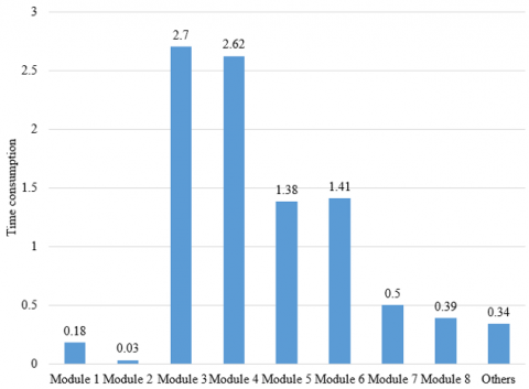
To realize thermal management and control of inverter system, the control frequency of target system and the switching cycle of IGBT module need to be fully considered to ensure that the complete operation time of the entire model is appropriate and the proportion of execution time of each sub-module is controllable. In case that the control frequency of target system was less than 20 kHz and the switching cycle of IGBT module was 50us, the running time of the model constructed in this paper was about 5~6us, which basically meets the requirement. In addition, the computation time consumption of each sub-module of the model was also calculated, and the results are given in Figure 6. Specifically, the tested modules include: the module for calculating average output power and variance of the new energy power generation system (Module 1), the module for calculating the rated power time proportion (Module 2), the output power prediction module (Module 3), the IGBT heat loss calculation module (Module 4), the system state estimation module (Module 5), the module for solving the optimal control sequence and control quantity of the system (Module 6), signal collection and pre-processing module (Module 7), heat management control signal output module (Module 8), etc.
Figure 5. Maximum IGBT junction temperature deviation under different observation modes
Figure 6. Computation time consumption of each module
According to the figure, although Model 3 (it predicts output power based on based on ANN) and Module 4 (it calculates the IGBT heat loss of multiple devices) had added a large computational load to the execution of the model, and this paper had set a constraint on Module 6 (it calculates the optimal control sequence and control quantity of the system), still, the computation time consumption took a large proportion, therefore, to further reduce the complete operation time of the entire model and accelerate the thermal management control signal output, further optimization could be made starting from these three modules.
To verify the validity of the temperature prediction model of inverter system, at first, the thermal management controller script file was closed and observations of the inverter system were made under the condition that there’s no intervention of thermal management and control. The simulated temperature curve and actually measured temperature curve of the inverter system are shown in Figure 7.
Figure 7. Comparison of simulated temperature and measured temperature
According to Figure 7, under the condition that there’s no thermal management control intervention, the simulated temperature curve and the actually measured temperature curve show a high degree of agreement, indicating that the temperature prediction model of the target system is effective. Then, the thermal management controller script file was opened, and simulations were performed under the condition of with and without thermal management control intervention, and the temperature curves are shown in Figure 8.
Figure 8. Temperature control curves under different thermal management control intervention conditions
As can be seen from Figure 8, under the intervention of thermal management and control, the operating temperature of the inverter system had been kept between 30℃~40℃. The temperature peak shown around 1000 seconds was mainly caused by the momentary fluctuations and increase of the output power of the new energy power generation system, the switching frequency of switching devices was accelerated and the heat generated by the system was increased. In most time period, the temperature of the inverter system was controlled below 40℃.
Table 3. System energy consumption before and after predictive temperature control
|
Control strategy |
Energy consumption (kwh) |
Energy saving ratio |
|
Before control |
1.67 |
/ |
|
After control |
1.44 |
13.5% |
At last, an experiment was designed to compare the system energy consumption before and after taking predictive temperature control, and the experimental data is given in Table 3. As can be seen from the data, the thermal management control strategy of inverter system introducing predictive temperature control could attain higher control accuracy and lower energy consumption; after taking predictive temperature control, the system energy consumption had been reduced by 0.23 kWh, and it had saved about 13.5% of the energy.
This paper studied a thermal management strategy of inverter system based on predictive control. At first, based on time-varying state space, a temperature prediction and control model of inverter system was built to calculate system state and control variables based on estimation with the mutual effect of different control variables taken into consideration and without the necessity of system decoupling. Then, this paper proposed a thermal management control strategy of inverter system based on predictive control and optimized it further. Combining with experiment, this paper gave the data of temperature rise of each component in the inverter system under high and low power conditions and the data of cooling system under different heat dissipation schemes, the results verified that the temperature rise of the new energy power generation system can be effectively controlled when the output power is in a peak state, and the heat dissipation performance of the inverter system could meet requirement. During the experiment, the calculation time consumption of each sub-module of the model was calculated to ensure that the complete operation time of the entire model was appropriate and the proportion of execution time of each sub-module was controllable. Moreover, the temperature control curves under the intervention of different thermal management and control schemes were compared and the results verified the validity of the constructed temperature prediction model of inverter system. At last, the system energy consumption before and after predictive temperature control was comparatively experimented, and the results proved that the strategy that introduced predictive temperature control could get higher control accuracy with lower energy consumption.
[1] Liu, Y., Zhu, M., Huang, M., Zha, X. (2022). An event-oriented reliability assessment for DC link capacitors in grid connected inverter with low voltage ride through operation. Microelectronics Reliability, 138: 114768. https://doi.org/10.1016/j.microrel.2022.114768
[2] Dou, Z., Chen, Z., Yang, Y., Song, J., Zheng, A., An, X. (2022). Reliability improvement of a 3-level t-type grid-connected inverter with dual vector modulation model predictive fault-tolerant control strategy. In 2022 IEEE 5th International Conference on Electronics Technology (ICET), Chengdu, China, pp. 395-400. https://doi.org/10.1109/ICET55676.2022.9824751
[3] Guo, X., Wu, Z., Luo, R., Lu, Z., Hua, C. (2022). Topology and control of five-level transformerless grid-connected inverter with high reliability. Automation of Electric Power Systems, 46(5): 151-158.
[4] Yao, Z. (2021). Single-stage high reliability doubly grounded nonisolated PV grid-connected inverter. International Transactions on Electrical Energy Systems, 31(6): e12898. https://doi.org/10.1002/2050-7038.12898
[5] Fang, T., Zhang, X., Huang, C., He, W., Shen, L., Ruan, X. (2019). Control scheme to achieve multiple objectives and superior reliability for input-series-output-parallel LCL-type grid-connected inverter system. IEEE Transactions on Industrial Electronics, 67(1): 214-224. https://doi.org/10.1109/TIE.2019.2897546
[6] Villanueva, I., Vázquez, N., Vaquero, J., Hernández, C., López, H., Osorio, R. (2020). L vs. LCL filter for photovoltaic grid-connected inverter: A reliability study. International Journal of Photoenergy, 2020: 7872916. https://doi.org/10.1155/2020/7872916
[7] Cui, C. (2020). Development of a high reliability three-phase PV grid-connected inverter circuit. In 2020 7th International Forum on Electrical Engineering and Automation (IFEEA), Hefei, China, pp. 399-403. https://doi.org/10.1109/IFEEA51475.2020.00090
[8] Cai, W., Yao, Z. (2022). Highly reliable dual-ground lift-voltage PV grid-connected inverter. in 2022 Power System and Green Energy Conference (PSGEC), Shanghai, China, pp. 308-312. https://doi.org/10.1109/PSGEC54663.2022.9881080
[9] Fu, Z., Feng, Z., Chen, X., Zheng, X. (2019). High-reliability three-phase dual-buck grid-connected inverter without shoot-through problem. Journal of Power Electronics, 19(2): 454-462. https://doi.org/10.6113/JPE.2019.19.2.454
[10] Sarwat, A., McCluskey, P., Mazumder, S.K., et al. (2022). Reliability assessment of grid connected solar inverters in 1.4 MW PV plant from anomalous classified real field data. In 2022 North American Power Symposium (NAPS), Salt Lake City, UT, USA, pp. 1-6. https://doi.org/10.1109/NAPS56150.2022.10012172
[11] Zhou, D., Wang, H., Blaabjerg, F. (2018). Reactive power impacts on LCL filter capacitor lifetime and reliability in DFIG grid-connected inverter. In 2018 IEEE Energy Conversion Congress and Exposition (ECCE), Portland, OR, USA, pp. 4094-4101. https://doi.org/10.1109/ECCE.2018.8558156
[12] Lu, Z., Zhong, Y., Peng, Z., et al. (2022). Optimal PWM frequency acquisition method based on parallel structure of IGBT and WBG inverter. In 2022 4th International Conference on Power and Energy Technology (ICPET), Beijing, China, pp. 323-328. https://doi.org/10.1109/ICPET55165.2022.9918495
[13] Rajeswaran, N., Thangaraj, R., Mihet-Popa, L., Krishna Vajjala, K. V., Özer, Ö. (2022). FPGA implementation of ai-based inverter IGBT open circuit fault diagnosis of induction motor drives. Micromachines, 13(5): 663. https://doi.org/10.3390/mi13050663
[14] Hassanifar, M., Shamouei-Milan, M., Neyshabouri, Y. (2022). T-type nested neutral point clamped (T-NNPC) multilevel inverter: Identification and diagnosis of IGBT switch failures. In 2022 13th Power Electronics, Drive Systems, and Technologies Conference (PEDSTC), Tehran, Iran, pp. 409-413. https://doi.org/10.1109/PEDSTC53976.2022.9767315
[15] Peng, Y., Chu, K., Mu, S., Cao, H., Wang, H. (2021). Parasitic effect compensation method for IGBT on-state voltage measurement in traction inverter application. IEEE Transactions on Power Electronics, 37(5): 4937-4941. https://doi.org/10.1109/TPEL.2021.3130209
[16] Dou, Z., Yang, Y., Zheng, A., Wang, N. (2022). A critical fault-tolerant inverter based on internal evolutionary short-circuit failure mechanism of IGBT module. IEEE Transactions on Components, Packaging and Manufacturing Technology, 12(12): 1914-1921. https://doi.org/10.1109/TCPMT.2022.3229084
[17] Trani, R., Catalano, A.P., Castellazzi, A., D'Alessandro, V. (2019). Thermal management solutions for a lightweight 3L GaN inverter. In 2019 10th International Conference on Power Electronics and ECCE Asia (ICPE 2019-ECCE Asia), Busan, Korea (South), pp. 2173-2178. https://doi.org/10.23919/ICPE2019-ECCEAsia42246.2019.8797312
[18] Xia, G., Zhuang, D., Ding, G. (2019). Thermal management solution for enclosed controller used in inverter air conditioner based on heat pipe heat sink. International Journal of Refrigeration, 99: 69-79. https://doi.org/10.1016/j.ijrefrig.2018.12.020
[19] Bentheimer, C., Islami, A., Mainusch, S., Hilpert, F., Eckardt, B., Maerz, M. (2019). Highly efficient SiC inverter for aircraft application with innova-tive thermal management. In PCIM Europe 2019; International Exhibition and Conference for Power Electronics, Intelligent Motion, Renewable Energy and Energy Management, Nuremberg, Germany, pp. 1-8.
[20] Huang, S., Chen, Y., Liu, P., Rong, F. (2017). Band-oriented active thermal management control of PWM inverter. Electric Power Automation Equipment, 37(5): 34-39.
[21] Boulter, R. (2021). Thermal management with ceramic cooling solution for drive inverters. Interceram-International Ceramic Review, 70: 14-17. https://doi.org/10.1007/s42411-021-0455-y
[22] van der Broeck, C.H., De Doncker, R.W. (2021). Increasing torque capability of AC drives via active thermal management of inverters. IEEE Transactions on Industry Applications, 57(6): 6277-6287. https://doi.org/10.1109/TIA.2021.3103812
[23] Abramushkina, E., Zhaksylyk, A., Geury, T., El Baghdadi, M., Hegazy, O. (2021). A thorough review of cooling concepts and thermal management techniques for automotive WBG inverters: topology, technology and integration level. Energies, 14(16): 4981. https://doi.org/10.3390/en14164981
[24] Mistry, J., Wang, Y., Azer, P., Bilgin, B. (2021). Design of a compact thermal management system for a high-power silicon carbide traction inverter. SAE Technical Paper, 2021-01-0218. https://doi.org/10.4271/2021-01-0218
[25] Cheli, L., Carcasci, C. (2021). Model-based development of a diagnostic algorithm for central inverter thermal management system fault detection and isolation. In 2021 5th International Conference on System Reliability and Safety (ICSRS), Palermo, Italy, pp. 14-21. https://doi.org/10.1109/ICSRS53853.2021.9660763
[26] Guirguis, D., Nasr, M., Murray, S.K., Matsumoto, H., Trescases, O., Amon, C.H. (2018). Thermal management within multi-disciplinary system design of a rubik’s-cube-sized 2kw power inverter. In 2018 17th IEEE Intersociety Conference on Thermal and Thermomechanical Phenomena in Electronic Systems (ITherm), San Diego, CA, USA, pp. 921-926. https://doi.org/10.1109/ITHERM.2018.8419549
[27] Chang, T.C., Fuh, Y.K., Lu, H.Y., Tu, S.X. (2016). Thermal management and performance evaluation of a dual bi-directional, soft-switched IGBT-based inverter for the 1st autonomous microgrid power system in Taiwan under various operating conditions. Heat and Mass Transfer, 52: 1231-1241. https://doi.org/10.1007/s00231-015-1628-x