Budhi Muliawan Suyitno*![]() | Dwi Rahmalina
| Dwi Rahmalina![]() | Ismail
| Ismail![]() | Reza Abdu Rahman
| Reza Abdu Rahman![]()
© 2023 IIETA. This article is published by IIETA and is licensed under the CC BY 4.0 license (http://creativecommons.org/licenses/by/4.0/).
OPEN ACCESS
Fast-charging mode thermal energy storage (TES) can be obtained by improving the average heat transfer rate of the system. However, it leads to the risk of performance deterioration for the long-term operation. The impact of charging rate for paraffin and FS-Paraffin (form-stable paraffin) is evaluated in the present work. The heating/cooling process is repeated for 10,000 cycles with different charging rate (1℃/min, 5℃/min and 10℃/min). The performance is focused on the discharging rate and thermal decomposition. It shows that the fast-mode treatment causes a severe deceleration in the discharging speed. The lowest discharging rate of paraffin is obtained at 0.64℃/min. The FS-Paraffin is generally better to withstand from thermal deterioration. It has a suitable discharging rate (0.82℃/min) with the lowest state of health (SoH) percentage of 97.3%. It implies that the presence of polymer additive (20 wt% high-density polyethylene) for FS-Paraffin reduces the impact of fast-charging operation. Further evaluations are discussed in the article, including the impact on SoH, thermal conductivity and storing performance. The overall condition indicates that thermal deterioration likely occurred during the fast-mode operation and requires extensive protection to maintain the long-term operation of the TES material.
charging speed, HDPE, PCM, state of health, thermal stress
The energy demand is increased exponentially as a side effect of growth in the global population and economy. It makes the exploration and deployment of new energy sources necessary to ensure the energy supply to society. The exploration and reactivation of oil and gas wells can be taken as an alternative approach to ensure the fuel reserve in the short term [1]. On the other hand, the utilization of renewable energy sources based on hydropower, solar and wind energy are escalated and taken as a promising method to sustain the clean energy system. It can specifically address the success story of wind power for electricity production, which contributes to a substantial portion of the global energy mix [2]. Solar energy plays in broader aspects besides electric production since it can be used as suitable thermal power generation for industrial and residential sectors [3]. The role of thermal energy storage (TES) in solar thermal systems is indispensable and has a significant impact on dispatchability and cost per unit of energy.
TES operates similarly to an electrical battery which employs energy storage material. It uses a material with a high specific heat capacity for sensible TES and melting fusion for latent TES [4]. The combination of specific heat capacity and melting fusion can be found in the phase change material (PCM), which promotes a higher energy density compared to the sole operation system (whether sensible or latent). It becomes the main advantage of PCM from latent TES since it works based on phase transition and a higher temperature range for operation in sensible mode [5]. Petroleum wax (paraffin) is an excellent example of PCM in low temperature TES system due to its high thermal capacity and economically feasible as it is considered the waste of crude oil.
Improvement on the latent TES, which uses paraffin as the storage material is done to overcome the poor heat releasement process due to low thermal conductivity and unstable transition during melting/solidification process [6]. The heat transfer rate can be improved effectively by embedding paraffin with high thermal conductivity materials as well as using a modified storage tank for active latent TES [7]. Thermal conductivity enrichment is mainly employed graphite powder [8], iron oxide (Fe3O4) [9] and sustainable material such as volcanic ash [10]. Improvement on the storage container is done by promoting high overall heat transfer coefficient by using finned storage container [11] and spiderweb arrangement to increase the thermal distribution within the tank [12]. The efforts are contributed positively in term of faster heat transfer process and more responsive thermal system.
The thermal stability is crucial for paraffin as PCM in latent TES which can be improved by using polymer as shape-stabilizer. The method contributes to promote a positive impact by reducing the leakage rate of the PCM during the phase transition [13]. Moreover, the form-stable paraffin (FS-Paraffin) shows a more stable heat transfer process during phase transition which can be achieved by using high-density polyethylene (HDPE) as the supporting matrix for paraffin [14]. The HDPE based FS-Paraffin is preferable since it has a good compatibility with paraffin and cost-effective method [15-17]. It leads to a significant achievement where the proposing method has a higher technology level and suitable for mass production [18].
Thermal conductivity enrichment and heat transfer improvement promote a better TES system and reducing the operational cost during the charging process. Unfortunately, it has a higher risk for long-term durability due to fast energy operation from the storage material. For instance, the risk of melting enthalpy decrement occurs after 200 thermal cycles as a result of repeating melting and solidification process [19]. The side effect is also observed which alter the phase transition behavior after 100 thermal cycles [20]. It affects the FS-Paraffin in similar manner where the FS-Paraffin experiences the decrement on melting enthalpy and charging/discharging rate after 5,000 cycles due to thermal disruption [21]. Furthermore, the thermal treatment through accelerated aging thermal cycles scenario provides the reasonable limitation for the decrement of performance and storage capacity of paraffin as PCM in latent TES [22].
Designing a higher energy transfer rate for latent TES using high thermal conductivity material and proper storage tank should be taken into account for the long-term operation and potential deterioration on its performance. Lesson learned from electrical battery where system with high energy transfer rate (also known as fast-charging battery) tend to have a higher performance degradation after certain cycle operation [23-25]. The study addresses the gap of the charging pattern after certain cycle on the long-term performance of paraffin as PCM. Particularly, the performance is specifically aimed for the characteristic of heat releasement process and the percentage of state of health (SoH). Compositing HDPE and paraffin (FS-Paraffin) is expected to maintain the long-term operation of paraffin [26] which make it suitable as performance comparison on the thermal treatment process.
The study considers the thermal treatment based on the common operation of paraffin in latent TES system. It is measured as the temperature change per unit time (℃/min). Thus, the current works takes the heating rate of 1℃/min as slow mode operation (SM), heating rate of 5℃/min as normal mode operation (NM) and high heat transfer rate of 10℃/min which defined as fast mode operation (FM). The heat releasement process is evaluated through discharging plot according to the active model which employs the heat transfer fluid. Moreover, the pattern of thermal decomposition and storing test (static and dynamic) are also evaluated to provide more in detail analysis on the impact if thermal treatment and charging pattern. Thus, the present work is expected to provide important reference on the consideration of long-term operation of paraffin as PCM in latent TES and understand the impact of charging rate on the system.
The present works use commercial grade of paraffin wax and HDPE as the reference material for thermal treatment and evaluation. The basic thermophysical properties are presented in Table 1. The HDPE works as shape-stabilizer to promote a better thermal stability and stable operation during phase change. Nevertheless, the addition of HDPE decreases the latent heat capacity of paraffin at the given melting temperature of paraffin. Thus, the ratio of HDPE should be limited to ensure the ideal capacity of paraffin reminds effective. The present study uses the 20 wt% mass ratio for the HDPE in FS-paraffin by considering the effective latent heat capacity and designation for active operation [27-29].
Table 1. Detailed thermophysical properties of paraffin and HDPE
|
Properties |
Paraffin |
HDPE |
|
Density (g/cm3) |
0.89 |
0.92 |
|
Melting point (℃) |
60 |
110 |
|
Melting enthalpy (J/g) |
188.2 |
125.4 |
|
Heat capacity (J/g·℃) |
2.18 |
1.59 |
|
Thermal conductivity (@30℃, W·m-1·K-1) |
0.214 |
0.415 |
The composite FS-Paraffin were mixed at liquid phase. The HDPE was melt using electric heater at temperature 160℃. The molten paraffin was poured gradually into the molten HDPE. The mixture was stirred by using mechanical stirrer for half an hour. Then, the mixture was set at room temperature for solidification. After that, the mixture was reheated and restirred to ensure the proper dispersion between paraffin and HDPE. The mass of sample for thermal treatment and evaluation was 100 grams.
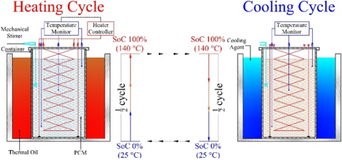
The thermal treatment was done using the temperature-based state of charge (SoC) as specific operation reference. Figure 1 presents the detailed schematic of the treatment process. The lowest temperature was taken at 25℃ which defines the storage capacity of 0% (SoC 0%). Then, the maximum temperature was taken at 140℃ where the system has fully charged (SoC 100%). The maximum temperature was defined above 100℃ by considering the probability of the application using cascade system [30]. Also, the average melting temperature of HDPE is around 110℃ which make the system need to operate higher than its melting temperature.
Figure 1. Schematic design for thermal treatment process
The thermal treatment was taken during the heat uptake process (charging). The heater controller was used to manage the heating rate within the container based on the charging scenario (SM, NM and FM). Two types electric heater were used within the container (coil and band heater) to ensure uniform heating process. Three thermometers (thermocouple type–K) were installed at different height to monitor the temperature of the sample. The heating process was done once the average temperature of the sample reached 140℃. The process continued to cooling cycle where the container moved to the cooling bath. The process kept repeated up 10,000 times. The process allows the sample to experience the actual heating/cooling cycle which similar to the actual application in the latent TES system.
The aged sample then taken for thermogravimetric test to observe the characteristic of thermal decomposition of the sample under different treatment scenarios. The performance test was taken according to the model of active test where the temperature can be used precisely to estimate the energy content of the sample. Also, heat releasement profile and percentage of state of health (SoH) can be obtained based on the test. Moreover, the proposed test was taken according to the recommendation of IEA ECES Annex 30 [31] which is essential as technical parameter for thermal storage system.
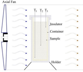
(a) Static test
(b) Dynamic test
Figure 2. Model test rig for storing test
The risk of heat loss during storing mode is likely occurred on the unit thermal storage [32-34]. Thus, it can be taken as one critical parameter to determine the performance of TES material. Therefore, the present study also evaluates the storing performance of the sample after thermal treatment at specific charging mode. First, the sample was heated up to 140℃ within a container. Then, the container was placed at the insulator (polyoxymethylene). Three thermocouples were located at different heights inside the container to monitor the temperature change during the test. For the static storing test (Figure 2a), the sample was located inside a small wind tunnel at a wind speed of 1 m/s with an average air temperature of 25℃. The dynamic test was used water as the cooling media (Figure 2b). The water flow was kept constant at a mass flow rate of 0.1 kg.s-1 with a temperature of 25℃. The baffle inside the chamber was designed to enhance the heat transfer process. From the measurement, two storing scenarios can be compared to evaluate the effect of storing environment on the storage period.
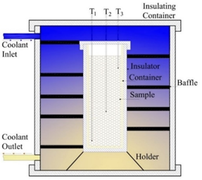
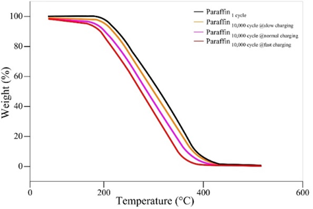
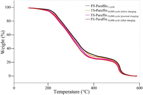
Thermogravimetric curve can be used to evaluate the thermal stability of the paraffin and FS-paraffin after thermal treatment. Figure 3a shows different profile of the decomposition curve of paraffin after 10,000 cycles. It indicates the typical decomposition with a single-go mass loss during the heating process which starts around 185℃ to 380℃. The change is clearly observed on the initial and the end of the decomposition process where it leads to an early decompose of the paraffin after 10,000 cycles. The impact of charging mode, particularly for fast mode, is observed notably where the end of decomposition occurs at relatively low temperature (around 352℃) with mass loss more than 95%. It implies the decrement on thermal stability of paraffin as the direct impact of repeating fast heat transfer rate during the process.
(a) Paraffin
(b) FS-Paraffin
Figure 3. Thermal decomposition curve after different thermal treatment
FS-Paraffin demonstrates a different pattern compared to paraffin. As seen in Figure 3b, it has two stage decomposition curve which indicates different decomposition temperature between paraffin and HDPE. The HDPE has a higher thermal stability by mean of a higher thermal decomposition which make the changes in the curve of FS-Paraffin. The impact of thermal treatment still occurs for the FS-paraffin at slightly decrement on the decomposition curve. The slight changes make the FS-Paraffin able to maintain sufficient heat energy which implies a higher thermal stability, even after 10,000 fast-mode thermal cycles. It emphasizes the role of HDPE which act as shape stabilizer and improve the thermal stability of paraffin.
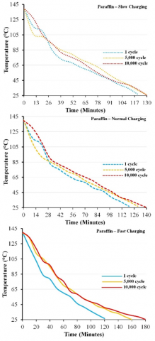
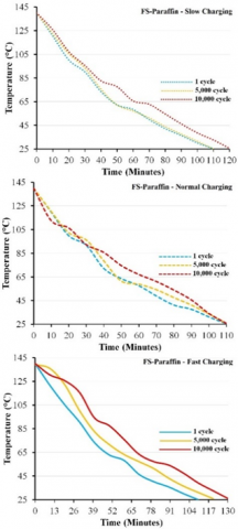
The slow exothermic process during solidification process occurs slowly due to poor thermal diffusion of hydrocarbon compound. It can be observed in Figure 4 where both samples (paraffin and FS-Paraffin) indicate a slower discharging process. For instance, Figure 4a demonstrates the discharge of the stored heat for paraffin takes more than 100 minutes to achieve the lowest SoC (0%). The impact of thermal treatment worsened it which make the duration gets even longer. The discharging rate reduces substantially after 10,000 thermal treatments. Moreover, the fast-mode treatment reduces the thermal deliverability which has the lowest discharging rate.
(a) Paraffin
(b) FS-Paraffin
Figure 4. Heat releasement profile during under different thermal treatment
The average of the discharged heat after slow mode treatment is obtained around 0.94 ℃/min – 0.88 ℃/min. Then, it becomes lower as the charging mode increased. The normal mode treatment leads to a slower discharging rate around 0.95 ℃/min – 0.82 ℃/min. It makes the average discharging rate decreases by 0.13 ℃/min. The most significant decrement is observed for the sample after fast-mode treatment. The average discharging rate ranges between 0.95℃/min – 0.64℃/min. Considering the slowing mode as the basic measurement, then the discharging rate is decreased around 116% and 417% after normal and fast mode treatment respectively. The impact should be taken into account during the design process since the discharging rate becomes slower which reduces the effective power of the storage system.
The FS-Paraffin experiences the effect of thermal treatment which makes the heat transfer becomes slower after 10,000 cycles (Figure 4b). However, it can be observed distinctively that the discharging rate of FS-Paraffin is relatively higher than paraffin. It has the average of temperature decrement around 1.04 ℃/min – 0.95 ℃/min after slow mode treatment and maintain sufficient discharging rate after normal mode treatment (at average of 1.04 ℃/min). The benefit of HDPE as thermal stabilizer can be observed on the characteristic of discharging curve where FS-Paraffin has a shorter duration to achieve SoC 0%. Also, it protects the paraffin from thermal stress and severe hysteresis losses after 10,000 fast-mode thermal treatment. For instance, the average heat decrement after 10,000 fast-mode treatment is obtained around 0.96 ℃/min – 0.87 ℃/min. Therefore, it can be said that there is no substantial change on the discharging rate for FS-Paraffin after 10,000 fast-mode thermal treatment. Unfortunately, it shows no plateau line during phase transition which make the heat releasement process occur non-isothermally.
(a) Paraffin
(b) FS-Paraffin
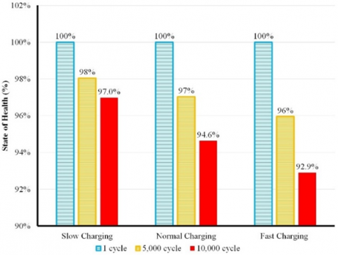
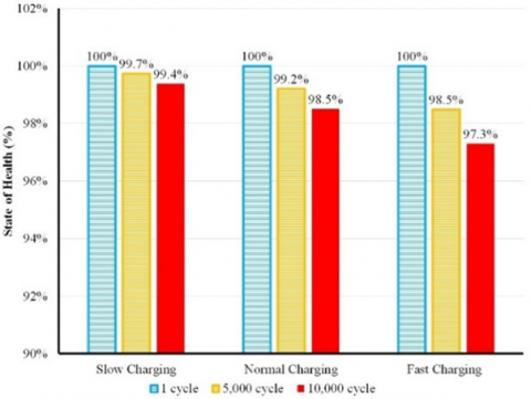
Figure 5. The state of health (SoH) percentage
The value of state of health (SoH) from material storage is set at 100% after the commissioning since it has the maximum capacity before the actual operation. Repeating the cycle along with the usage of the system causes the decrement of SoH percentage as the impact of charging/discharging process [35]. As it can be seen in Figure 5, the SoH for paraffin and FS-Paraffin reduces after the cycling treatment. Figure 5a shows the impact of repeating cycle and charging mode is observed clearly after 10,000 cycles for paraffin. It maintains sufficient SoH after 5,000 cycles with an average decrement around 5%. The fast-mode treatment leads to substantial SoH decrement about 7.1%. It makes the effective storage capacity for paraffin as storage material drops significantly after 10,000 fast-mode operation.
The suitable thermal stability for FS-Paraffin (Figure 3b) contributes positively to maintain the percentage of SoH. As seen in Figure 5b, the SoH of FS-Paraffin for the all-treatment mode decreases less than 3%. The SoH percentage falls once the storage material cannot maintain its actual thermal capacity based the setting time of the operation (charging and discharging duration). For FS-Paraffin, the satisfactory thermal capacity is maintained as the present of HDPE which protects the paraffin from the impact of repeating heating/cooling process. It can be observed for the discharging profile of FS-Paraffin (Figure 4b) where the average heat releasement rate is considerably higher than paraffin and maintain its value after fast-mode operation.
(a) Paraffin
(b) FS-Paraffin
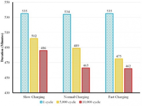
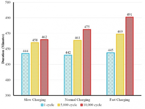
Figure 6. The duration of static storage test
The examination of functionality from of the storing mode for thermal storage tank were conducted by using identic storage tank without thermal insulator which makes the heat losses solely depend on the storage material [36]. It can be seen on the peculiar pattern of storing test for paraffin and FS-Paraffin related to the total storing duration. The trend indicates a certain decrement of storing duration for paraffin after thermal cycles (Figure 6a). Oppositely, the FS-Paraffin shows an increment of the storing duration for the aged sample (after thermal treatment). The main reason for this phenomenon is the nature of heat transfer for both samples. The static storage test uses air as heat transfer media and the heat diffusion occurs around the outside wall of the storage tank. The disruption along with freezing process for paraffin is caused by supercooling phenomenon [37] which contributes to the change on the duration of static storing test. FS-Paraffin contains HDPE that minimizes the impact of supercooling phenomenon. Even though there is a trend on the increment of supercooling degree for the aged storage material, the deceleration of heat releasement due to slow thermal diffusion during static storge test reduces the crystal growth rate of the FS-Paraffin (Figure 6b). As a result, the FS-Paraffin tends to has a longer storing duration after 10,000 fast-mode cycle.
(a) Paraffin
(b) FS-Paraffin
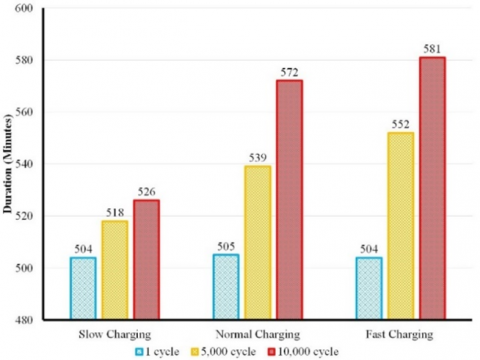
Figure 7. The duration of dynamic storage test
A more in detail comparison can be made from Figure 7 where the dynamic storage test indicates the opposite result of static storage test. It demonstrates that paraffin has a longer duration after 10,000 cycles and gets longer after fast-mode operation (Figure 7a). In contrast, FS-Paraffin experiences an acceleration of heat losses after 10,000 thermal cycles (Figure 7b). The pattern implies that the heat losses vary based on the thermal diffusion at the outside of the tank wall [38]. For instance, the slow convection rate from air (static test) causes the rapid solidification for paraffin and perhaps promote a higher void formation due to fast-mode operation. Oppositely, it can be minimized by improving the heat transfer rate at the outer wall of the tank during the to promote a better thermal distribution within the storage tank.
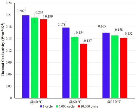
The pattern of heat releasement both during discharging and storing process indicate a change in the heat transfer rate along with thermal treatment, particularly for fast-mode treatment. It can be seen that the fast-mode thermal treatment leads to significant performance deterioration after 10,000 cycles. In order to evaluate its impact, thermal conductivity measurement was conducted for the aged sample after 10,000 fast-mode thermal treatment. The measurement was taken according to the transient plane sources method (TPS-3500). Since paraffin has temperature-dependent for the thermophysical properties [39], then the measurement was conducted at three different temperatures: 40℃, 60℃ and 110℃. The temperature was determined by considering the initial crystalline change for paraffin at temperature of 40℃. Also, the temperature of 60℃ and 110℃ were chosen since it relates to the area melting temperature for paraffin and HDPE, respectively.
(a) Paraffin
(b) FS-Paraffin
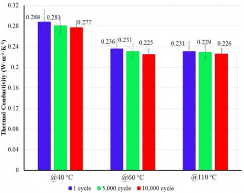
Figure 8. The average thermal conductivity after 10,000 fast-mode thermal treatment
The effect of fast-mode thermal treatment alters the average thermal conductivity for each temperature region (Figure 8). The decrement on the thermal conductivity for paraffin at temperature of 40℃ is around 5%. It seems the wax has a better stability in solid phase which maintains sufficient the average thermal conductivity (Figure 8a). However, on the area of phase transition (60℃) and liquid phase (110℃) the thermal conductivity reduces substantially. The phase transition area experiences the highest decrement by value of 23% and followed by the liquid phase which decreased by 7.8%. It implies the phase transition region as vulnerable area which severely affected by the thermal treatment and fast-mode operation. It seems the repeating heating/cooling process deteriorate the molecular bonding within the wax. As a result, it leads to the decrement of energy transfer rate (heat). It also promotes the disorientation at the molecular level which decelerated the phase transition rate and extend the duration of mushy region formation which significantly reduces the heat transfer performance.
The HDPE generally has a higher thermal conductivity than paraffin but still considered low for thermal storge system (less than 1 W·m-1·K-1). However, it helps the FS-Paraffin to maintain sufficient thermal conductivity (Figure 8b). For example, the phase transition area of FS-Paraffin (which occur relatively close temperature to paraffin wax) only experiences decrement of thermal conductivity by value of 4.6%, which much lower than paraffin. The high thermal stability of HDPE which accompanied by a slightly higher thermal conductivity promotes protect the FS-Paraffin from severe thermal degradation and maintain the molecular bonding. It can be observed at temperature of 110℃ which is the phase transition region of HDPE which only decreases by 0.22%. At this point, the HDPE plays critical role to maintain the performance of paraffin and increase the thermal stability to minimize the impact of fast-mode and long-term operation in latent TES system.
The present work demonstrates the impact of charging mode for paraffin as PCM in latent TES. The change in decomposition curve and significant decrement in discharging rate deteriorate severely the actual operation of TES system after 10,000 cycles. The FS-Paraffin which made of HDPE and paraffin is advantageous to maintain the discharging and decomposition rate after 10,000 cycles. It indicates the performance of the latent TES system can be maintained sufficiently. For instance, the fast-mode thermal treatment causes the discharging rate of paraffin decreases to 0.64℃/min while FS-Paraffin able to keep the discharging rate up to 0.87℃/min. The static and dynamic storage test imply the importance of using proper insulator to maintain the storage capacity effectively during the storing period. Thermal treatment also influences the thermal conductivity of paraffin and FS-Paraffin. It corresponds to the decrement of the discharging performance and need to address as crucial factor for long-term operation of paraffin and FS-Paraffin in latent TES system.
The impact can be minimized by setting periodical maintenance and model for changing the storage material in order to maintain the performance of the storage system. The fast-charging mode is highly importance for any storage system since it reduces the charging duration and improve the system reliability and effectiveness during the operation. Compositing paraffin with HDPE may be considered as important reference to maintain the long-term performance of paraffin in latent TES system. Thermal conductivity improvement optimizes the overall thermal performance of TES system. Thus, adding suitable thermal conductivity material and compositing paraffin with HDPE can be taken as the ideal approach to produce a high-performance latent TES system. Further study can be conducted by focusing the overall economy impact as well as defining the periodical maintenance and energy balance for the latent TES system to provide more in detail impact on the long-term operation of TES system.
The authors were grateful to The Ministry of Education, Culture, Research, and Technology the Republic of Indonesia as being the funder of research under scheme Penelitian Dasar Unggulan Perguruan Tinggi.
[1] Ismail, I., Mulyanto, A.T., Rahman, R.A. (2022). Development of free water knock-out tank by using internal heat exchanger for heavy crude oil. EUREKA: Physics and Engineering, (4): 77-85. https://doi.org/10.21303/2461-4262.2022.002502
[2] Ismail, I., Rahman, R.A., Haryanto, G., Pane, E.A. (2021). The optimal pitch distance for maximizing the power ratio for savonius turbine on inline configuration. International Journal of Renewable Energy Research (IJRER), 11(2): 595-599. https://dorl.net/dor/20.1001.1.13090127.2021.11.2.10.9.
[3] Krishna, Y., Faizal, M., Saidur, R., Ng, K.C., Aslfattahi, N. (2020). State-of-the-art heat transfer fluids for parabolic trough collector. International Journal of Heat and Mass Transfer, 152: 119541. https://doi.org/10.1016/j.ijheatmasstransfer.2020.119541
[4] Liu, M., Riahi, S., Jacob, R., Belusko, M., Bruno, F. (2020). Design of sensible and latent heat thermal energy storage systems for concentrated solar power plants: Thermal performance analysis. Renewable Energy, 151: 1286-1297. https://doi.org/10.1016/j.renene.2019.11.115
[5] Klimeš, L., Charvát, P., Joybari, M.M., Zálešák, M., Haghighat, F., Panchabikesan, K., El Mankibi, M., Yuan, Y. (2020). Computer modelling and experimental investigation of phase change hysteresis of PCMs: The state-of-the-art review. Applied Energy, 263: 114572. https://doi.org/10.1016/j.apenergy.2020.114572
[6] Khademi, A., Shank, K., Mehrjardi, S.A.A., Tiari, S., Sorrentino, G., Said, Z., Chamkha, A.J., Ushak, S. (2022). A brief review on different hybrid methods of enhancement within latent heat storage systems. Journal of Energy Storage, 54: 105362. https://doi.org/10.1016/j.est.2022.105362
[7] Wu, S., Yan, T., Kuai, Z., Pan, W. (2020). Thermal conductivity enhancement on phase change materials for thermal energy storage: A review. Energy Storage Materials, 25: 251-295. https://doi.org/10.1016/j.ensm.2019.10.010
[8] Alvar, M.Z., Abdeali, G., Bahramian, A.R. (2022). Influence of graphite nano powder on ethylene propylene diene monomer/paraffin wax phase change material composite: Shape stability and thermal applications. Journal of Energy Storage, 52: 105065. https://doi.org/10.1016/j.est.2022.105065
[9] Lu, B., Zhang, Y., Zhang, J., Zhu, J., Zhao, H., Wang, Z. (2022). Preparation, optimization and thermal characterization of paraffin/nano-Fe3O4 composite phase change material for solar thermal energy storage. Journal of Energy Storage, 46: 103928. https://doi.org/10.1016/j.est.2021.103928
[10] Suyitno, B.M., Rahmalina, D., Rahman, R.A. (2023). Increasing the charge/discharge rate for phase-change materials by forming hybrid composite paraffin/ash for an effective thermal energy storage system. AIMS Materials Science, 10(1): 70-85. https://doi.org/10.3934/matersci.2023005
[11] Ismail, Syahbana, M.S.L., Rahman, R.A. (2022). Thermal performance assessment for an active latent heat storage tank by using various finned-coil heat exchangers. International Journal of Heat and Technology, 40(6): 1470-1477. https://doi.org/10.18280/ijht.400615
[12] Wu, L., Zhang, X., Liu, X. (2020). Numerical analysis and improvement of the thermal performance in a latent heat thermal energy storage device with spiderweb-like fins. Journal of Energy Storage, 32: 101768. https://doi.org/10.1016/j.est.2020.101768
[13] Gandhi, M., Kumar, A., Elangovan, R., Meena, C.S., Kulkarni, K.S., Kumar, A., Bhanot, G., Kapoor, N.R. (2020). A review on shape-stabilized phase change materials for latent energy storage in buildings. Sustainability, 12(22): 9481. https://doi.org/10.3390/su12229481
[14] Rahmalina, D., Rahman, R.A., Ismail (2022). Improving the phase transition characteristic and latent heat storage efficiency by forming polymer-based shape-stabilized PCM for active latent storage system. Case Studies in Thermal Engineering, 31: 101840. https://doi.org/10.1016/j.csite.2022.101840
[15] Molefi, J.A., Luyt, A.S., Krupa, I. (2010). Comparison of LDPE, LLDPE and HDPE as matrices for phase change materials based on a soft Fischer–Tropsch paraffin wax. Thermochimica Acta, 500(1-2): 88-92. https://doi.org/10.1016/j.tca.2010.01.002
[16] Cheng, W.L., Zhang, R.M., Xie, K., Liu, N., Wang, J. (2010). Heat conduction enhanced shape-stabilized paraffin/HDPE composite PCMs by graphite addition: preparation and thermal properties. Solar Energy Materials and Solar Cells, 94(10): 1636-1642. https://doi.org/10.1016/j.solmat.2010.05.020
[17] Xu, L., Liu, X., Yang, R. (2020). Flame retardant paraffin-based shape-stabilized phase change material via expandable graphite-based flame-retardant coating. Molecules, 25(10): 2408. https://doi.org/10.3390/molecules25102408
[18] Sciacovelli, A., Navarro, M.E., Jin, Y., Qiao, G., Zheng, L., Leng, G., Wang, Y., Ding, Y. (2018). High density polyethylene (HDPE)—Graphite composite manufactured by extrusion: A novel way to fabricate phase change materials for thermal energy storage. Particuology, 40: 131-140. https://doi.org/10.1016/j.partic.2017.11.011
[19] Vasu, A., Hagos, F.Y., Mamat, R., Kaur, J., Noor, M.M. (2019). The effect of thermal cyclic variation on the thermophysical property degradation of paraffin as a phase changing energy storage material. Applied Thermal Engineering, 149: 22-33. https://doi.org/10.1016/j.applthermaleng.2018.12.033
[20] Wang, Q., Zhou, D., Chen, Y., Eames, P., Wu, Z. (2020). Characterization and effects of thermal cycling on the properties of paraffin/expanded graphite composites. Renewable Energy, 147: 1131-1138. https://doi.org/10.1016/j.renene.2019.09.091
[21] Rahmalina, D., Rahman, R.A., Ismail (2022). Increasing the rating performance of paraffin up to 5000 cycles for active latent heat storage by adding high-density polyethylene to form shape-stabilized phase change material. Journal of Energy Storage, 46: 103762. https://doi.org/10.1016/j.est.2021.103762
[22] Zhang, L., Dong, J. (2017). Experimental study on the thermal stability of a paraffin mixture with up to 10,000 thermal cycles. Thermal Science and Engineering Progress, 1: 78-87. https://doi.org/10.1016/j.tsep.2017.02.005
[23] Li, Y., Gao, X., Feng, X., Ren, D., Li, Y., Hou, J., Wu, Y., Du, J., Lu, L., Ouyang, M. (2022). Battery eruption triggered by plated lithium on an anode during thermal runaway after fast charging. Energy, 239: 122097. https://doi.org/10.1016/j.energy.2021.122097
[24] Zhou, R., Zhu, R., Huang, C.G., Peng, W. (2022). State of health estimation for fast-charging lithium-ion battery based on incremental capacity analysis. Journal of Energy Storage, 51: 104560. https://doi.org/10.1016/j.est.2022.104560
[25] Mathieu, R., Briat, O., Gyan, P., Vinassa, J. M. (2021). Fast charging for electric vehicles applications: Numerical optimization of a multi-stage charging protocol for lithium-ion battery and impact on cycle life. Journal of Energy Storage, 40: 102756. https://doi.org/10.1016/j.est.2021.102756
[26] Rahman, R.A., Lahuri, A.H., Ismail. (2023). Thermal stress influence on the long-term performance of fast-charging paraffin-based thermal storage. Thermal Science and Engineering Progress, 37: 101546. https://doi.org/10.1016/j.tsep.2022.101546
[27] Palacios, A., Navarro, M.E., Barreneche, C., Ding, Y. (2020). Hybrid 3 in 1 thermal energy storage system–Outlook for a novel storage strategy. Applied Energy, 274: 115024. https://doi.org/10.1016/j.apenergy.2020.115024
[28] Wang, Y., Zhou, J., Wei, G., Dong, Z., Chen, H. (2016). Stator winding single-phase grounding faults protective scheme based on discriminant analysis for powerformers with selectivity. International Journal of Electrical Power & Energy Systems, 77: 145-150. https://doi.org/10.1016/j.ijepes.2015.11.037
[29] Rahman, R.A., Suwandi, A., Nurtanto, M. (2021). Experimental investigation on the effect of thermophysical properties of a heat transfer fluid on pumping performance for a convective heat transfer system. Journal of Thermal Engineering, 7(7): 1628-1639. https://doi.org/10.18186/thermal.1025910
[30] Nekoonam, S., Roshandel, R. (2021). Modeling and optimization of a multiple (cascading) phase change material solar storage system. Thermal Science and Engineering Progress, 23: 100873. https://doi.org/10.1016/j.tsep.2021.100873
[31] Gibb, D., Seitz, A., Johnson, M., Romani, J., Gasia, J., Gabeza, L.F., Gurtner, R., Vandersickel, A. (2018). Applications of thermal energy storage in the energy transition-Benchmarks and developments. Lehrstuhl für Energiesysteme.
[32] Araújo, A.K., Medina T., G.I. (2018). Analysis of the effects of climatic conditions, loading level and operating temperature on the heat losses of two-tank thermal storage systems in CSP. Solar Energy, 176: 358-369. https://doi.org/10.1016/j.solener.2018.10.020
[33] Allan, J., Croce, L., Dott, R., Georges, G., Heer, P. (2022). Calculating the heat loss coefficients for performance modelling of seasonal ice thermal storage. Journal of Energy Storage, 52: 104528. https://doi.org/10.1016/j.est.2022.104528
[34] Haller, M.Y., Yazdanshenas, E., Andersen, E., Bales, C., Streicher, W., Furbo, S. (2010). A method to determine stratification efficiency of thermal energy storage processes independently from storage heat losses. Solar Energy, 84(6): 997-1007. https://doi.org/10.1016/j.solener.2010.03.009
[35] Thonon, M., Fraisse, G., Zalewski, L., Pailha, M. (2021). Analytical modelling of PCM supercooling including recalescence for complete and partial heating/cooling cycles. Applied Thermal Engineering, 190: 116751. https://doi.org/10.1016/j.applthermaleng.2021.116751
[36] Tehrani, S.S.M., Shoraka, Y., Nithyanandam, K., Taylor, R.A. (2019). Shell-and-tube or packed bed thermal energy storage systems integrated with a concentrated solar power: A techno-economic comparison of sensible and latent heat systems. Applied Energy, 238: 887-910. https://doi.org/10.1016/j.apenergy.2019.01.119
[37] Shamseddine, I., Pennec, F., Biwole, P., Fardoun, F. (2022). Supercooling of phase change materials: A review. Renewable and Sustainable Energy Reviews, 158: 112172. https://doi.org/10.1016/j.rser.2022.112172
[38] Deng, J., Furbo, S., Kong, W., Fan, J. (2018). Thermal performance assessment and improvement of a solar domestic hot water tank with PCM in the mantle. Energy and Buildings, 172: 10-21. https://doi.org/10.1016/j.enbuild.2018.04.058
[39] Chiu, Y.J., Yan, W.M., Chiu, H.C., Jang, J.H., Ling, G.Y. (2018). Investigation on the thermophysical properties and transient heat transfer characteristics of composite phase change materials. International Communications in Heat and Mass Transfer, 98: 223-231. https://doi.org/10.1016/j.icheatmasstransfer.2018.09.011