Ismail* | Muhammad Syukur Liffan Syahbana | Reza Abdu Rahman
© 2022 IIETA. This article is published by IIETA and is licensed under the CC BY 4.0 license (http://creativecommons.org/licenses/by/4.0/).
OPEN ACCESS
Paraffin-based latent heat storage has a higher thermal capacity than sensible heat storage. Despite that, the actual implementation of paraffin as an active latent heat storage (ALHS) system is limited due to low charging and discharging rate with unequal temperature distribution as the impact of mushy region formation. The present study evaluates the finned-coil heat exchanger for the ALHS tank to overcome the related problems. Three finned-coil configurations are tested experimentally: straight-fin, branched-fin and height-fin. The evaluation uses the ALHS arrangement to assess each configuration's charging/discharging rate. The branched fin provides an equal thermal distribution, promoting a higher final temperature of 112.3°C. It also achieves the highest power rate of 250.5 Watts. The height-fin minimizes the effect of void formation, which maintains a sufficient heat transfer rate during the discharging. However, the average power rate for each model is relatively low. The finding indicates that it is essential to provide adequate heat transfer for the center part of the tank, including adding a branched fin along with coil turn to provide a better heat transfer rate. It boosts the charging/discharging rate, making the system's response time desirable to achieve effective power during the operation.
heat exchanger, phase change material, mushy region, void formation, power effective
The need for clean energy has become a major issue, while at the same time, energy security from fossil fuels is also considered an important topic. Harvesting wind and solar power as renewable energy sources are proven to develop a clean energy supply. Continuous development for improving the system, particularly for implementing a suitable wind farm layout to improve the plant's energy density, continuously supports the readiness to supply power to the system [1]. Reactivating an old oil well for short mitigation [2] and improving the burner for solid biomass waste [3] can be taken as an alternative approach to exploring new energy sources and increasing the efficiency of the existing system. Perhaps, harvesting solar energy through a photovoltaic system for electric generation and concentrated solar power as a thermal plant is the most profound technology in renewable energy systems [4]. The dispatchability of the plant can be improved with the help of advanced technology in the system. Also, an enormous improvement in the energy storage system contributes positively to the renewable energy plant. It helps to reduce operational costs and make the system economically favorable.
Thermal energy storage (TES) is considered an innovative energy storage system that can be applied both for small and large-scale applications [5]. TES uses sensible and phase change material (PCM) to store heat. It can be applied as a suitable method for reducing the primary energy consumption in heating and cooling application [6]. The sensible material is the most available method but suffers from low storage density, both in gravimetric and volumetric capacity [7]. The PCM provides a higher energy density since it works based on phase transition, which also can be combined as sensible material during the charging process [8]. Therefore, effective energy capacity can be achieved, reducing the cost per unit of energy.
One of the most common materials for latent heat storage is paraffin wax. Paraffin is advantageous as PCM since it has a high melting enthalpy and low cost [9]. Furthermore, the wax is non-corrosive, making it suitable for various storage tanks. It has been successfully implemented as a passive thermal storage system in building and housing applications [10]. The shortcoming issue from the wax is the leakage issue. It occurs during phase transition and can be minimized by compositing the wax with polymer to form shape-stabilized phase change material (SSPCM) [11]. Furthermore, the method is also suitable for improving the cycling ability, which can be used for up to 10,000 thermal cycles without significant decrement in the storage capacity [12]. Thus, the method is already processed for large-scale manufacturing and is expected to significantly reduce production costs [13].
Besides the passive storage system, paraffin is also suitable for implementing an active latent heat storage system (ALHS). It works by using working fluid as the heat transfer medium, making it possible for wider applications such as solar dryers [14]. The ALHS stored the paraffin within the storage tank and coupled it with a heat exchanger. The working fluid flows to provide a heat exchange process to the storage material. The ALHS can be operated up to 100°C. It can also be combined using a multi-storage tank to develop a cascade storage system [15]. However, the major challenge for ALHS is the heat exchanger configuration within the storage tank since it relates to the charging/discharging cycle. The heat exchanger designation must consider the effective heat transfer area without decreasing the storage capacity. Moreover, it must consider the effect of paraffin's unstable phase transition, which interrupts the heat transfer process.
A continuous effort has been made to maximize paraffin's charging/discharging cycle in an ALHS system. Faghiri et al. [16] develop an innovative method using intermediate boiling fluid (IBF) for heat exchange and effectively improves the heat transfer rate during discharging cycle. Veismoradi et al. [17] utilizes a storage tank by using shell and tube arrangement for the heat exchange process. The study combines PCM with metal foam and heat pipe, where the system achieves a significant increment in the charging/discharging cycle. Barz conducts numerical analysis for the heat exchanger with plate-fin to improve the heat transfer process to the storage material. The study recommends the fin configuration to reduce the hysteresis effect during the heating/cooling cycle to ensure effective heat energy transfer [18]. Using a fin in the heat exchanger is desirable since it is relatively simple to implement and enhance the heat transfer area to the storage material. Mehta et al. develop a spiral-fin configuration that accelerates the charging/discharging rate by 41.48% and 22.16%, respectively [19].
The recommended heat exchanger configuration for the ALHS tank is the coil heat exchanger with a compact body and large heat transfer area [20-22]. Adding a fin on the coil heat exchanger is expected to improve the system's overall performance, particularly for the charging/discharging cycle, with an unsubstantial decrement in the storage capacity [23]. Further study is also conducted by embedding the fin with a single tube configuration. Wu et al. use a spider-web-like heat exchanger within the storage tank to improve the heat transfer surface to the storage material. The numerical study indicates a rapid solidification up to 47.9% where the charging rate is improved substantially by a value of 1.44 times [24]. The advanced fin configuration is also studied by Shalaby et al. [25] for application in shell and tube heat exchangers. The study focuses on the system arrangement with a solar collector, which shows a considerable improvement in daily efficiency by up to 65%.
Further development on the finned-coil heat exchanger is still relevant as it can be adjusted using multiple fin configurations within the storage tank. Remarkably, the void formation generally occurs during the solidification process [26], which makes the crater formation at the center of the storage tank that can be reduced by utilizing an extra fin at the center part of the coil [27]. In good agreement with the recent development in finned-coil heat exchangers for ALHS tanks, the present study proposes several configurations for the coil heat exchanger in ALHS tanks. Three fin configurations are evaluated experimentally to improve the charging/discharging cycle of the ALHS system and support continuous development in the ALHS tank. The result of the study is expected to present sufficient information and a novel approach for designing the ALHS tank.
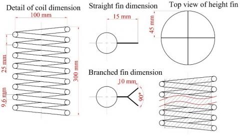
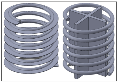
The convective heat transfer system for active latent heat storage requires interaction between the working fluid and storage material using the recuperative heat exchanger principle. The coil heat exchanger has main advantages, with a high surface area and a relatively small index volume. Figure 1a displays the present study's basic model of the coil heat exchanger. The modification was applied by adding flat-fin along with the coil turns to provide a straight-fin model. The second variation was applied using a branched fin instead of a flat fin. The third variation is the height-fin model, which was installed at the center of the storage tank. The 3D model for straight-fin (also as a basic model for branched fin) and height fin is presented in Figure 1b. The height-fin was specifically intended to overcome the void formation issue during the solidification process of paraffin wax.
(a) Detailed dimension
(b) Example for 3D design
Figure 1. Configuration for coil heat exchanger
The total stored and released energy by the storage material (paraffin) is the amount of energy gained during sensible (solid and liquid) stage and melting/freezing process. The total sensible energy is obtained from Eq. (1) [28]:
$\begin{aligned} & \Delta Q_{\text {sen }}=\left(m \cdot c_{p, \text { solid }} \cdot \Delta T_{\text {solid }}\right)+\left(m \cdot c_{p, l q i u i d} \cdot \Delta T_{\text {liquid }}\right)\end{aligned}$ (1)
Then, the total energy during phase transition can be obtained from Eq. (2) [28]:
$\Delta Q_{\text {latent }}=(m \cdot \Delta h)$ (2)
where, m is the mass of storage material (kg), cp is specific heat capacity at solid and liquid phase (kJ·kg-1·°C-1), ΔT is the temperature difference for each sensible stage (°C) and Δh is the melting enthalpy (kJ·kg-1).
The specific heat capacity for paraffin (isotherms) at solid and liquid phase were obtained at 2.18 kJ·kg-1·°C-1 and 1.85 kJ·kg-1·°C-1, respectively. The thermal properties of paraffin wax (commercial grade) were assessed using differential scanning calorimetry and thermogravimetric analysis (DSC/TGA, MT +1). It was taken to evaluate the wax's melting/freezing temperature and melting enthalpy. Furthermore, thermal stability as part of thermal properties is essential to understand the decomposition curve during the heating process. After evaluating the thermal properties, an active charging/discharging assessment was conducted for each configuration of the coil heat exchanger. The test was taken by using active latent heat storage apparatus where the charging process is defined as the material absorbing thermal energy from the working fluid and discharging process is defined as the heat releasement process from the material to the working fluid.
Figure 2. Schematic model for charging and discharging test
The ALHS concept were taken as the configuration for the experimental test. The active model employs the heat interaction between the thermal source and load by the help of working fluid [29]. The phase change of the storage material deliberates a higher energy content which maximized by the solid and liquid sensible stage. Therefore, the working fluid temperature was kept constant at 160°C (charging) and 20°C (discharging). The changes in temperature of the working fluid can be used for determining the energy balance to evaluate the effective power and energy from the storage material. Using a higher temperature range provides a combined solid sensible-phase transition-liquid sensible stage which highly desirable for the cascade latent heat system [30]. The operation of cascade system offers a higher energy density which make it possible to be used in various application [31]. Thus, the experiment was performed by using the high temperature range to meet the criteria of actual application.
Figure 2 displays the measurement location during the active thermal charging/discharging test. Each coil arrangement was tested under the same working boundary which make the power comparison is taken as the ideal quantitative index to determine the performance of each model [32]. The power index is obtained by dividing the total energy that stored/released by the paraffin with the total duration to achieve the targeted temperature. Therefore, three locations of the temperature measurement (using thermocouple type–K) were taken for the paraffin within the storage tank: T1 (upper zone), T2 (middle zone) dan T3 (lower zone). Locating the temperature measurement at a different location was aimed at monitoring the temperature profile of the storage material during the charging and discharging test. The temperature of the working fluid was measured at the inlet (Tin) and outlet port (Tout). The storage tank used a well-insulated aluminum tank with a 9 kg paraffin wax capacity. The flow rate of the working fluid (thermal oil) was set at 2.5 g/s and maintained during the test.
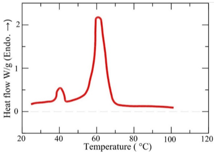
Figure 3 presents the paraffin's heating and cooling curve from differential scanning calorimetry (DSC). The heating curve (Figure 3a) indicates two distinguished peaks at different temperatures. The first peak, which relatively occurs earlier at a temperature of 39.7°C is defined as a solid-solid transition resulting from a heating process that alters the movement of the crystalline structure from the wax. As the heating process continues, the phase change is occurred from solid to liquid which is indicated by a larger second peak. The changes in heat flux under the second peak is the total energy required for melting process. The highest peak indicates the melting temperature. Thus, two critical properties area obtained: the melting temperature and enthalpy. The second peak is observed at a temperature of 60.9°C with the heat of fusion of 189.6 J.g-1. After passing the phase transition, the wax is in the liquid phase without indicating a new peak, which means the sensible liquid heating stage takes place.
(a) Heating curve
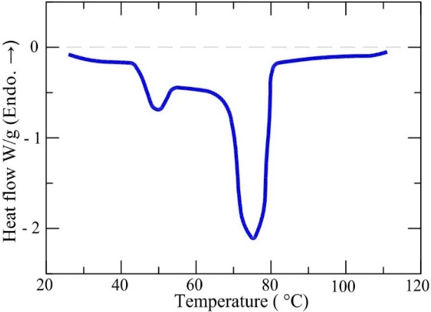
(b) Cooling curve
Figure 3. DSC curve for paraffin wax
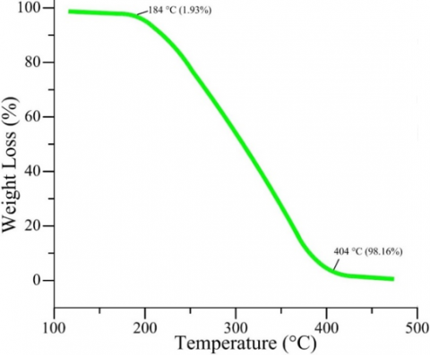
The essential aspect of the thermal properties of the paraffin wax can be observed from the cooling curve (Figure 3b), which shows the freezing temperature occurs at 75.1°C. It implies a high deviation between the melting and freezing temperatures which can be considered a supercooling phenomenon. Supercooling takes place when rapid solidification occurs at a higher temperature than the wax's melting temperature [33]. The supercooling degree is relatively high by a value of 14.2°C, which is undesirable for the actual application of an active latent heat storage system. Furthermore, the decomposition curve of paraffin runs as a single-go pattern (Figure 4). The wax starts to decompose at 184°C up to 404°C, with a mass loss of more than 98%. It implies that paraffin wax has low thermal stability.
Figure 4. Thermal decomposition for paraffin wax (thermogravimetric curve)
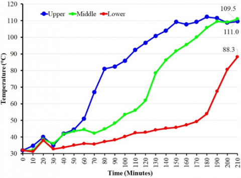
The charging process runs by supplying heat to the paraffin wax with the help of the working fluid. The profile temperature during the charging process is presented in Figure 5. All profiles show that the temperature keeps increasing after passing the melting temperature of the paraffin wax. It demonstrates that paraffin wax has a non-isothermal phase transition, which makes the solid-liquid transition followed directly by a temperature increment. Implements paraffin as a storage material for an active system is troublesome since the system cannot be set at a specific temperature for the operation, particularly for a system that requires a sensitive-temperature operation such as a thermal management system [34]. However, using different coil configuration indicate a substantial change in the charging profile of the paraffin.
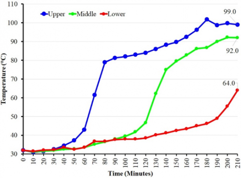
As seen in Figure 5, the temperature at the upper zone is generally higher than in the middle and lower zone. It is affected by a direct heat transfer from a high-temperature working fluid at the upper zone that promotes a higher heat transfer and increases the paraffin's temperature significantly. The temperature profile of straight-fin (Figure 5a) demonstrates a distinguished temperature pattern for each zone. It can be observed by a slow temperature increment at the middle and lower zone. A high-temperature difference between each zone indicates a slow melting process of paraffin. The upper zone melts first, followed by the middle and lower zones. Thus, the thermal diffusion and buoyancy effect are localized at the upper zone, reducing the heat transfer rate of the storage material at the middle and lower zones.
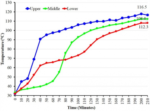
The branched fin (Figure 5b) indicates an appropriate temperature increment with a slight temperature variation at the end of the charging stage for all zones (108°C – 116.5°C). It implies that the paraffin wax obtains a better temperature distribution since the coil utilizes an extra fin extension, increasing the surface area for the heat transfer process. The buoyancy effect can be minimized since the lower and upper zone melts relatively at the moment, promoting a better temperature distribution for the middle area of the storage tank. It can be observed from Figure 5b that the intercept line of the temperature at the upper and lower zone takes place after 70 – 80 minutes. After that, the temperature at the center part of the storage tank increases rapidly. Therefore, the final temperature for the upper, middle and lower zone is generally close since the heat is distributed properly.
The height-fin configuration shows a contrasting temperature distribution compared to the branched and straight-fin configurations. As observed in Figure 5c, the final temperature of the storage tank is less than 100°C. Furthermore, the temperature variation between the upper, middle and lower zone is relatively large. Even though the height-fin temperature profile is relatively similar to the straight-fin (Figure 5a) in terms of inadequate temperature distribution, the charging rate of the height-fin is slow. It indicates a poor thermal distribution since the system cannot absorb sufficient heat under a specified time. The height-fin and straight-fin show unequal temperature distribution. However, the straight-fin maintains a sufficient charging rate since it achieves a higher final temperature than the height-fin.
(a) Straight fin
(b) Branched fin
(c) height-fin during
Figure 5. Profile temperature of the charging process
(a) Straight fin
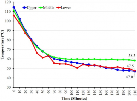
(b) Branched fin
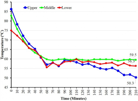
(c) Height-fin during
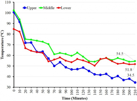
Figure 6. Profile temperature of the discharging process
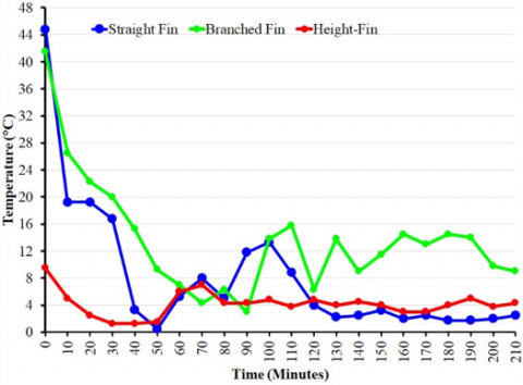
Figure 6 presents the temperature decrement during the discharging process, indicating various temperature profiles for each coil configuration. The unstable heat releasement process is observed for the straight find configuration (Figure 6a). It can be observed by unstable temperature decrement at the upper, middle and lower zone. Again, the lowest final temperature of the storage tank is obtained at the upper zone as it releases heat effectively to the low-temperature working fluid. As the temperature of the working fluid increases, the heat releasement at the middle and lower zone becomes slower. As a result, the final temperature at the middle and lower zone remains high by 54.5°C and 51.8°C, respectively. It is caused by the supercooling phenomenon of the paraffin (Figure 3b), which promotes a rapid solidification process and disturbs the heat transfer process during the phase transition. Since the upper zone freezes earlier, the static pressure from the upper part deteriorates the heat releasement process at the middle and lower zone, which is still in the liquid phase.
The height-fin configuration shows a better thermal distribution during the discharging process (Figure 6c). Even though the model demonstrates a poor charging rate, the heat release process during the discharging stage is relatively stable due to locating the extra fin in the center part of the coil. The fin reduces the effect of void formation, which promotes better heat transfer and delivers a stable temperature decrement of the paraffin. The void formation occurs as the impact of the mushy region creates a crater in the middle area of the storage tank [35]. Thus, adding a fin in the center part of the coil promotes better heat distribution and reduces the effect of mushy region formation. Consequently, the final temperature during the discharging stage ranges from 50.3°C to 59.5°C. Despite that, the same model still indicates a low discharging rate as the final temperature of the storage material remains high.
The branched-fin configuration boosts the temperature decrement of the storage material, which indicates an optimal temperature distribution (Figure 6b). It is indicated by the profile of temperature decrement from the storage material, which is reasonably close to all zones. Furthermore, the final temperature of the paraffin wax is relatively low which ranging from 47.0°C – 58.3°C. The temperature of the paraffin wax drops to more than 60°C, which makes the stored energy can be released effectively during the discharging process. The effect of supercooling can be minimized by promoting a better temperature distribution which makes the temperature of the upper and lower zone remains close (47.0°C and 47.5°C, respectively). However, the final temperature of the middle zone is still relatively high as the impact of fast temperature decrement at the upper and lower zone makes the heat concentrated at the storage tank's center part.
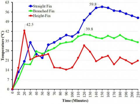
The heat interaction between the working fluid and storage material can be observed using the temperature differences between the inlet and outlet ports during the charging and discharging process. Figure 7a presents the temperature differences during the charging process for each coil configuration. It can be seen that the highest temperature difference is obtained by straight-fin configuration with the optimum value of 59.8°C. However, it seems the initial charging process is rather slow, making insufficient heat transfer to the storage material. The height-fin configuration demonstrates an extreme temperature variation during the process. It emphasizes the charging profile (Figure 5c), which tends to be slow and unstable during the process. The branched fin achieves the ideal model with a stable temperature increment variation. Even though the highest temperature difference is only 39.8°C, the temperature variation during the process is relatively small, indicating a suitable temperature distribution and sufficient heat release from the working fluid to the storage material. It is also supported by the charging profile for the branched fin (Figure 6b), which shows an adequate temperature distribution for the storage tank's upper, middle and lower zone.
(a) Charging process
(b) Discharging process
Figure 7. Temperature differences of the working fluid
The opposite result is shown for the height-fin, which implies a stable heat releasement process during the discharging process (Figure 7b). It indicates by a slight temperature fluctuation during the process. However, a stable heat releasement process is also accompanied by a slow discharging rate which makes the highest temperature difference less than 12°C. As a result, the slow temperature decrement during the discharging process (Figure 6c) makes only a small portion of the energy can be released from the storage material. The identic pattern is observed for the straight fin configuration with a peak temperature of 13.8°C for a short period during the process. The unstable phase transition also disturbs the heat releasement process for the branched fin, which also shows temperature fluctuation. It demonstrates the nature of paraffin wax during the heat releasement process, which is unstable and reduces the effective heat transfer rate.
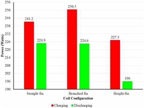
The effective power during the charging and discharging stage can be obtained by evaluating the heat interaction between the working fluid and storage material based on temperature differences. Effective power is a critical performance indicator for the active latent heat storage system [36]. Figure 8 shows an identic plot for each coil configuration where the effective power during charging stage is higher than the discharging process. Paraffin's melting process occurs adequately by a higher effective power during the charging process. However, the unstable charging process reduces the effective power, as can be observed for straight-fin and height-fin configurations. The branched-fin configuration demonstrates a sufficient temperature distribution, promoting sufficient effective power. It also implies that the configuration has a better optimal charging rate than the straight-fin and height fin.
Figure 8. Effective power during charging and discharging
The unstable discharging process affects the effective power of the system. A significant decrement is seen for the effective power during the discharging stage. The decrement occurs for each configuration. It can be concluded that the nature of the problem comes from the storage material. It is the main reason that promoting stable phase transition is critical for active latent heat storage [37]. The freezing mechanism of paraffin is a complex exothermic process involving slow nucleation that reduces the crystal growth rate. Thus, the supercooling disturbs the heat release process [38]. The lowest effective power during discharging stage is obtained by height-fin configuration with a value of 196 Watts. A low effective power proves a poor discharging rate, reducing the system's performance. The straight and branched fin configuration provides a better temperature distribution, which maintains effective power during the discharging stage.
The highest power effective ratio between charging/discharging is achieved by straight fin configuration with a value of 93.2%. Unfortunately, the same model expresses unequal temperature distribution within the storage tank, reducing the total capacity of stored heat during the charging stage. Contrary to that, the branched fin configuration demonstrates a lower effective power ratio of 86.9%. Despite that, the same configuration has a higher capacity compared to a straight fin. The configuration can be used as a basis model for further development by using various phase change materials, including the form stabilized phase change material that can provide a stable phase transition during the charging and discharging stages.
The present study demonstrates in detail that different coil configurations affect the paraffin wax's charging and discharging performance in an active latent heat storage tank. The branched fin configuration shows the highest charging rate of 0.53°C/min, providing significant temperature increments up to 80.3°C. As a result, the charging profile is relatively stable and fairly distributed for the entire zone of the storage tank. The single-go decomposition and supercooling phenomenon affect the discharging process significantly. For example, each configuration shows a substantial decrement in the discharging rate where the highest drop is obtained by height-fin configuration. However, the same configuration demonstrated a fair temperature distribution during the discharging stage compared to the straight fin. It is caused by installing a fin located at the center of the coil and storage tank, which minimizes void formation during solidification.
It implies that adding an extra fin and the coil turns positively contribute to a better charging/discharging rate. Thus, it can be taken as a basic model for developing a fast charging/discharging active latent heat storage tank. Further study is encouraged by addressing the effect of working boundaries based on different working fluids and convective heat transfer to understand the overall performance of the storage tank during the charging/discharging cycle. Thus, the ideal model of an active latent heat storage tank can be applied for thermal energy storage, reducing carbon emission and improving thermal renewable energy system reliability.
[1] Ismail, I., Rahman, R.A., Haryanto, G., Pane, E.A. (2021). The optimal pitch distance for maximizing the power ratio for savonius turbine on inline configuration. International Journal of Renewable Energy Research (IJRER), 11(2): 595-599. https://doi.org/10.20508/ijrer.v11i2.11862.g8181
[2] Ismail, I., Mulyanto, A.T., Rahman, R.A. (2022). Development of free water knock-out tank by using internal heat exchanger for heavy crude oil. EUREKA: Physics and Engineering, 4: 77-85. https://doi.org/10.21303/2461-4262.2022.002502
[3] Ismail, A.T., Ismail, I., Rahman, R.A. (2022). Increasing the reliability of biomass solid fuel combustion using a combined regenerative heat exchanger as an indirect burner. Eastern-European Journal of Enterprise Technologies, 5(8): 53-61. https://doi.org/10.15587/1729-4061.2022.265803
[4] Donga, R.K., Kumar, S. (2019). Thermal performance of parabolic trough collector with absorber tube misalignment and slope error. Solar Energy, 184: 249-259. https://doi.org/10.1016/j.solener.2019.04.007
[5] IRENA. (2020). Innovation Outlook: Thermal Energy Storage. https://www.irena.org/publications/2020/Nov/Innovation-outlook-Thermal-energy-storage.
[6] Bellos, E., Tzivanidis, C. (2018). Energetic and exergetic evaluation of a novel trigeneration system driven by parabolic trough solar collectors. Thermal Science and Engineering Progress, 6: 41-47. https://doi.org/10.1016/j.tsep.2018.03.008
[7] Darwesh, B.D., Hamakhan, I.A., Yaqob, B.N. (2022). Thermal enhancement of solar energy storage using phase change materials. International Journal of Heat and Technology, 40(3): 758-766. https://doi.org/10.18280/ijht.400314
[8] Suyitno, B.M., Rahmalina, D., Rahman, R.A. (2023). Increasing the charge/discharge rate for phase-change materials by forming hybrid composite paraffin/ash for an effective thermal energy storage system. AIMS Material Science 2023, 10: 70-85. https://doi.org/10.3934/matersci.2023005
[9] Khademi, A., Shank, K., Mehrjardi, S.A.A., Tiari, S., Sorrentino, G., Said, Z., Chamkha, A.J., Ushak, S. (2022). A brief review on different hybrid methods of enhancement within latent heat storage systems. Journal of Energy Storage, 54: 105362. https://doi.org/10.1016/j.est.2022.105362
[10] Marani, A., Madhkhan, M. (2021). Thermal performance of concrete sandwich panels incorporating phase change materials: An experimental study. Journal of Materials Research and Technology, 12: 760-775. https://doi.org/10.1016/j.jmrt.2021.03.022
[11] Rahmalina, D., Rahman, R.A. (2022). Improving the phase transition characteristic and latent heat storage efficiency by forming polymer-based shape-stabilized PCM for active latent storage system. Case Studies in Thermal Engineering, 31: 101840. https://doi.org/10.1016/j.csite.2022.101840
[12] Rahman, R.A., Lahuri, A.H. (2023). Thermal stress influence on the long-term performance of fast-charging paraffin-based thermal storage. Thermal Science and Engineering Progress, 37: 101546. https://doi.org/10.1016/j.tsep.2022.101546
[13] Sciacovelli, A., Navarro, M.E., Jin, Y., Qiao, G., Zheng, L., Leng, G., Wang, L., Ding, Y. (2018). High density polyethylene (HDPE)-Graphite composite manufactured by extrusion: A novel way to fabricate phase change materials for thermal energy storage. Particuology, 40: 131-140. https://doi.org/10.1016/j.partic.2017.11.011
[14] Alimohammadi, Z., Akhijahani, H.S., Salami, P. (2020). Thermal analysis of a solar dryer equipped with PTSC and PCM using experimental and numerical methods. Solar Energy, 201: 157-177. https://doi.org/10.1016/j.solener.2020.02.079
[15] Liu, M., Riahi, S., Jacob, R., Belusko, M., Bruno, F. (2020). Design of sensible and latent heat thermal energy storage systems for concentrated solar power plants: Thermal performance analysis. Renewable Energy, 151: 1286-1297. https://doi.org/10.1016/j.renene.2019.11.115
[16] Faghiri, S., Aria, H.P., Shafii, M.B. (2022). Multi-objective optimization of acetone droplet impingement on phase change material in direct-contact discharge method. Journal of Energy Storage, 46: 103862. https://doi.org/10.1016/j.est.2021.103862
[17] Veismoradi, A., Ghalambaz, M., Shirivand, H., Hajjar, A., Mohamad, A., Sheremet, M. (2021). Study of paraffin-based composite-phase change materials for a shell and tube energy storage system: A mesh adaptation approach. Applied Thermal Engineering 2021, 190: 116793. https://doi.org/10.1016/j.applthermaleng.2021.116793
[18] Barz, T. (2021). Paraffins as phase change material in a compact plate-fin heat exchanger-Part II: Validation of the “curve scale” hysteresis model for incomplete phase transitions. Journal of Energy Storage, 34: 102164. https://doi.org/10.1016/j.est.2020.102164
[19] Mehta, D.S., Vaghela, B., Rathod, M.K., Banerjee, J. (2020). Thermal performance augmentation in latent heat storage unit using spiral fin: an experimental analysis. Journal of Energy Storage, 31: 101776. https://doi.org/10.1016/j.est.2020.101776
[20] Raut, D., Lanjewar, S., Kalamkar, V.R. (2022). Effect of geometrical and operational parameters on paraffin's melting performance in helical coiled latent heat storage for solar application: A numerical study. International Journal of Thermal Sciences, 176: 107509. https://doi.org/10.1016/j.ijthermalsci.2022.107509
[21] Abdelsalam, M.Y., Sarafraz, P., Cotton, J.S., Lightstone, M.F. (2017). Heat transfer characteristics of a hybrid thermal energy storage tank with Phase Change Materials (PCMs) during indirect charging using isothermal coil heat exchanger. Solar Energy, 157: 462-476. https://doi.org/10.1016/j.solener.2017.08.043
[22] Kumar, A., Agrawal, R. (2022). An experimental investigation of cylindrical shaped thermal storage unit consisting of phase change material based helical coil heat exchanger. Journal of Energy Storage, 45: 103795. https://doi.org/10.1016/j.est.2021.103795
[23] Herbinger, F., Groulx, D. (2022). Experimental comparative analysis of finned-tube PCM-heat exchangers’ performance. Applied Thermal Engineering, 211: 118532. https://doi.org/10.1016/j.applthermaleng.2022.118532
[24] Wu, L., Zhang, X., Liu, X. (2020). Numerical analysis and improvement of the thermal performance in a latent heat thermal energy storage device with spiderweb-like fins. Journal of Energy Storage, 32: 101768. https://doi.org/10.1016/j.est.2020.101768
[25] Shalaby, S.M., Kabeel, A.E., Moharram, B.M., Fleafl, A.H. (2020). Experimental study of the solar water heater integrated with shell and finned tube latent heat storage system. Journal of Energy Storage, 31: 101628. https://doi.org/10.1016/j.est.2020.101628
[26] Janghel, D., Saha, S.K., Karagadde, S. (2020). Effect of shrinkage void on thermal performance of pure and binary phase change materials based thermal energy storage system: A semi-analytical approach. Applied Thermal Engineering, 167: 114706. https://doi.org/10.1016/j.applthermaleng.2019.114706
[27] Yang, B., Raza, A., Bai, F., Zhang, T., Wang, Z. (2019). Microstructural evolution within mushy zone during paraffin’s melting and solidification. International Journal of Heat and Mass Transfer, 141: 769-778. https://doi.org/10.1016/j.ijheatmasstransfer.2019.07.019
[28] Mehling, H., Cabeza, L.F. (2008). Basic thermodynamics of thermal energy storage. In: Heat and cold storage with PCM. Heat and Mass Transfer. Springer, Berlin, Heidelberg. https://doi.org/10.1007/978-3-540-68557-9_1
[29] Rahman, R.A., Suwandi, A., Nurtanto, M. (2021). Experimental investigation on the effect of thermophysical properties of a heat transfer fluid on pumping performance for a convective heat transfer system. Journal of Thermal Engineering, 7(7): 1628-1639. https://doi.org/10.18186/thermal.1025910 https://doi.org/10.14744/jten.2021.0006
[30] Fan, M., Luan, Z., Yang, H., Zhang, X., Hou, M., Guo, L., Kong, X. (2022). Charging and discharging characteristics of cascaded latent heat storage (CLHS) tank for low-temperature applications. Applied Thermal Engineering, 118698. https://doi.org/10.1016/j.applthermaleng.2022.118698
[31] Park, J., Choi, S.H., Karng, S.W. (2021). Cascaded latent thermal energy storage using a charging control method. Energy, 215: 119166. https://doi.org/10.1016/j.energy.2020.119166
[32] Roetzel, W., Luo, X., Chen, D.Z. (2020). Optimal design of heat exchangers. In Design and Operation of Heat Exchangers and their Networks. Academic Press, pp. 191-229. https://doi.org/10.1016/b978-0-12-817894-2.00005-4
[33] Shamseddine, I., Pennec, F., Biwole, P., Fardoun, F. (2022). Supercooling of phase change materials: A review. Renewable and Sustainable Energy Reviews, 158: 112172. https://doi.org/10.1016/j.rser.2022.112172
[34] Lilley, D., Lau, J., Dames, C., Kaur, S., Prasher, R. (2021). Impact of size and thermal gradient on supercooling of phase change materials for thermal energy storage. Applied Energy, 290: 116635. https://doi.org/10.1016/j.apenergy.2021.116635
[35] Tabassum, T., Hasan, M., Begum, L. (2018). Transient melting of an impure paraffin wax in a double-pipe heat exchanger: Effect of forced convective flow of the heat transfer fluid. Solar Energy, 159: 197-211. https://doi.org/10.1016/j.solener.2017.10.082
[36] Gibb, D., Seitz, A., Johnson, M., Romani, J., Gasia, J., Gabeza, L.F., Gurtner, R., Vandersickel, A. (2018). Applications of thermal energy storage in the energy transition-Benchmarks and developments. Lehrstuhl für Energiesysteme.
[37] Rahmalina, D., Rahman, R.A. (2022). Increasing the rating performance of paraffin up to 5000 cycles for active latent heat storage by adding high-density polyethylene to form shape-stabilized phase change material. Journal of Energy Storage, 46: 103762. https://doi.org/10.1016/j.est.2021.103762
[38] Klimeš, L., Charvát, P., Joybari, M.M., Zálešák, M., Haghighat, F., Panchabikesan, K., El Mankibi, M., Yuan, Y. (2020). Computer modelling and experimental investigation of phase change hysteresis of PCMs: The state-of-the-art review. Applied Energy, 263: 114572. https://doi.org/10.1016/j.apenergy.2020.114572