Adel H. Ayaal
© 2022 IIETA. This article is published by IIETA and is licensed under the CC BY 4.0 license (http://creativecommons.org/licenses/by/4.0/).
OPEN ACCESS
The air solar collectors are one of the necessary equipment for heating by increase the induced air temperatures. The thermal analysis of the solar air collector for the three different absorbers, flat and double slope (15, 30) degrees was studied numerically by employing a FORTRAN 90 program. The 3D steady-state forced convection turbulent technique was used to solve the Navier-Stokes with energy equations. The turbulence effect was modeled by using k-ε two equation model. The discretization of governing equations was done by finite volume technique. The test is carried out under the weather conditions of the Baghdad-Iraq region during the month of Jun. The results exhibit that the air temperatures increase when used the double slope collector, also the performance of air solar collector is enhanced thermally. The average 15° angle plate is higher than the flat and the 30° angle plates from 8am to 11am and from 1pm to 6pm, it is best slope angle.
CFD, solar collector, air temperature, double slope
Solar thermal collectors are one of the applications of renewable energy. Over the past years, many factors that affect the thermal performance of these collectors have been studied, with both collectors using water and those that use air as a working fluid. Where solar water collectors are used to produce hot water or preheat the heat factor needed for heating processes, whereas solar air collectors are used to reheat the air required for drying, sterilization, etc. [1, 2].
The thermal performance of solar air collectors has been improved by several methods by researchers, such as increasing the surface area of the solar collector, using phase changing materials (PCM), studying the effect of radiation incidence and other methods.
Rostami et al. [3] has studied the thermal analysis of flat plate collector with circular and elliptical tubes. From the results, it was found that the collector of elliptical tubes was the best in terms of useful energy and removal factor than the other as a result of large surface area. The study of two types of solar collectors and their comparison was presented by Amraoui [4], where the collector efficiency was increased by employing double pass in order to enhance heat transfer. Round, square and rectangular tubes have been studied theoretically by Xu et al. [5]. From the study, it was found that the rectangular cross-sections have high thermal performance compared to the other studied sections. Sardouei et al. [6] presented an analytical and numerical study of the cross-sectional designs of different thermal collectors. Through the study, it was found that square transverse tubes are better than round tube collectors in terms of heat transfer rate due to the large contact area. Labed et al. [7] presented an experimental study of thermal behavior of two models of single-pass solar collectors; initially, the flow direction in the collector was reversed, to obtain the optimum performance model and to improve the SAH efficiency factor. Hence, the thermal heat transfer coefficient for both collectors was evaluated. The results showed that the (air moving down) collector was more efficient than the other one.The performance of air solar collector with a movable absorber panels and glass covers on both sides a numerically has been studied by Dawood et al. [8]. The study found that the thermal performance was enhanced by 67% when the plates adjusting to the angle 0. While the highest value of thermal efficiency was reached to 51% at 0.0298 mass flow rate for the 90 degree angle. A numerical study of the flat plate air collector and another one of transverse obstacles to increase the surface area and thus increase the heat exchange process in addition to increasing turbulence was presented by Ong et al. [9] presented a study the effect of tilt angle of a flat-panel solar collector. The performance of a solar collector in case of natural convection is somewhat the same of photovoltaic for heat generation. The temperature of the photovoltaic panel rises when used in hot weather, which negatively affects its efficiency and life span. Through this study, some experimental results were studied about the effect collector tilt angle on the performance of flat plate collector. Two models to predict the thermal performance numerically of a solar air heater using paraffin wax based on latent heat storage and a conventional one have been studied by Salih et al. [10]. The finite volume technique was used to solve the equations of conservation of momentum, mass, and energy, as well as the phase enthalpy conversion that takes place in (PCM). The study showed that the solar intensity and mass flow rate of air had a significant impact on the amount of useful energy generated as well as the thermal performance of both models. Moreover, there was a clear enhancement in the collector efficiency using paraffin wax within the range of the studied variables. Hybrid nanoparticles with different concentrations were studied by Hussein et al. [11] as working fluids within a flat solar collector and Tween 80 (Tw-80) was used as a surfactant catalyst. Various measuring instruments were used to test the stability and thermophysical properties. As a result, the thermal efficiency of the collector has increased up to 85% at a flow rate of 4 l / min. The increase in nanoparticle concentrations enhanced the thermal energy gain and led to an increase in the fluid outlet temperature. Shamsul Azha et al. [12] presented a study that includes a review of ten methods for improving the heat transfer using vibration and its possible application to flat plat solar collector. These include: the use of nanofluids, absorbent coatings, (PCM), thermal performance enhancers, FPSC design modifications, the use of polymeric materials, heat loss reduction, mini-channel and micro-channel, and enhanced heat transfer using vibration. The effect of using longitudinal fins embedded inside PCM on the thermal behavior of the solar air collector in the weather of the city of Baghdad was studied by Abdulmunem et al. [13]. By comparing results for collectors with and without PCM, it was found that the use of PCM increases thermal energy of the collector, as well as using transverse obstacles with wax, which contributes to enhance thermal efficiency compared with collector using wax without fins. Three types of flat plate solar collectors have been studied experimentally by Blaise et al. [14]. The results showed that the use of baffles with flat plate solar air collectors significantly improves the thermal efficiency, as well as increases the air temperature outside the collector. A study was conducted by Jalil et al. [15] to perform a group of solar air collectors for the purpose of obtaining hot air, where the first collector was studied experimentally, while the other one was studied numerically with the same boundary conditions. Through the results, it was found that the efficiency was different from one collector to another, in addition to the possibility of determining the required number of sequential collectors needed to obtain the required outside air temperature. The thermal performance of the smooth plate solar collector was studied by Chabane and Moummi [16], through the study the behavior of this type of collector was discussed with the new design and appropriate construction.
Many researchers were focused on improving the thermal efficiency of air solar collectors. Because the position of the sun changes over any specific location on earth throughout the day because of the rotary motion of the earth around its axis, it is not possible to benefit from the same amount of solar radiation during the day. In this paper, the effect of double slope on thermal performance will be studied for the first time for an air solar collector, and it is known that the double slope is used in water distillation devices. The purpose of this study is to dispense with solar radiation tracking devices with high costs compared to the costs of this system. The solar radiations for the three different absorbers, flat and double slope (15, 30) degrees will be measured for possibility of improving the work of solar collector.
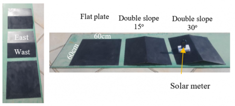
A three different absorber plates made of Aluminum with dimensions 0.6*0.6 m2 were tested by measuring the solar irradiations (using solar meter device) during the day. The three different absorbers are, flat and double slope (15, 30) degrees shown in Figure 1. The double slope plates were half in either sides (east and west sides). The position of collector was in the south direction to get optimum solar radiation. The test was carried out under the weather conditions of the Baghdad-Iraq region during the month of Jun (25/6/2022). The measurements were made by measuring the radiation intensity on the flat plate and on both sides of the double slope plate, then finding the average readings of east and west sides.
Figure 1. Flat and double slope (15°, 30°) absorber plates
In this study, a flat plate solar air heater will be studied. The collector dimensions are (1.2*0.4*0.03) m, which consists of the following parts: a 4 mm thick glass panel of thermal conductivity equal to 0.78 W/m.℃; The thickness of the air gap is 3 cm; The absorbent plate is iron with a 2 mm thickness of and 17 W/m.℃ thermal conductivity of. Figure 2 shows schematic diagram of the physical domain.
Figure 2. Schematic diagram for flat plate solar air heater
A three-dimensional incompressible numerical model was developed for describing flow behavior through a flat plate solar air heater. The Navier-Stokes equation with energy equation was discretized using a finite volume method and SIMPLE algorithm was used to solve the coupled of pressure and velocity fields [17]. k-ε two equation model was used to introduce the effect of turbulence. Hybrid difference scheme, with uniform staggered grids were employed. The governing equations are illustrated as follow:
i-Mass conservation:
$\frac{\partial(\rho u)}{\partial x}+\frac{\partial(\rho v)}{\partial y}+\frac{\partial(\rho w)}{\partial z}=0$ (1)
ii-Momentum conservation:
x-direction
$\frac{\partial(\rho u u)}{\partial x}+\frac{\partial(\rho v u)}{\partial y}+\frac{\partial(\rho w u)}{\partial z}=-\frac{\partial p}{\partial x}+$$\frac{\partial}{\partial x}\left(2 \mu_{e f f} \frac{\partial u}{\partial x}-\frac{2}{3} \mu_{e f f}\left(\frac{\partial u}{\partial x}+\frac{\partial v}{\partial y}+\frac{\partial w}{\partial z}\right)\right)+$$\frac{\partial}{\partial y}\left(\mu_{e f f}\left(\frac{\partial u}{\partial y}+\frac{\partial v}{\partial x}\right)\right)+\frac{\partial}{\partial z}\left(\mu_{\text {eff }}\left(\frac{\partial u}{\partial z}+\frac{\partial w}{\partial x}\right)\right)$ (2)
y-direction
$\begin{aligned} \frac{\partial(\rho u v)}{\partial x} & +\frac{\partial(\rho v v)}{\partial y}+\frac{\partial(\rho w v)}{\partial z}=-\frac{\partial p}{\partial y}+\frac{\partial}{\partial x}\left(\mu_{e f f}\left(\frac{\partial u}{\partial y}+\frac{\partial v}{\partial x}\right)\right) \\ & +\frac{\partial}{\partial y}\left(2 \mu_{e f f} \frac{\partial v}{\partial y}-\frac{2}{3} \mu_{e f f}\left(\frac{\partial u}{\partial x}+\frac{\partial v}{\partial y}+\frac{\partial w}{\partial z}\right)\right) \\ + & \frac{\partial}{\partial z}\left(\mu_{e f f}\left(\frac{\partial v}{\partial z}+\frac{\partial w}{\partial y}\right)\right)+\frac{\partial}{\partial z}\left(\mu_{e f f}\left(\frac{\partial v}{\partial z}+\frac{\partial w}{\partial y}\right)\right)\end{aligned}$ (3)
z-direction
$\frac{\partial(\rho u w)}{\partial x}+\frac{\partial(\rho v w)}{\partial y}+\frac{\partial(\rho w w)}{\partial z}=-\frac{\partial p}{\partial z}+\frac{\partial}{\partial x}\left(\mu_{\text {eff }}\left(\frac{\partial u}{\partial z}+\frac{\partial w}{\partial x}\right)\right)$
$+\frac{\partial}{\partial y}\left(\mu_{e f f}\left(\frac{\partial v}{\partial z}+\frac{\partial w}{\partial y}\right)\right)+$
$+\frac{\partial}{\partial z}\left(2 \mu_{\text {eff }} \frac{\partial w}{\partial z}-\frac{2}{3} \mu_{e f f}\left(\frac{\partial u}{\partial x}+\frac{\partial v}{\partial y}+\frac{\partial w}{\partial z}\right)\right)$ (4)
iii-Energy conservation:
$\frac{\partial(\rho u T)}{\partial x}+\frac{\partial(\rho v T)}{\partial y}+\frac{\partial(\rho w T)}{\partial z}=\frac{\partial}{\partial x}\left(\Gamma_{\text {eff }} \frac{\partial T}{\partial x}\right)$$+\frac{\partial}{\partial y}\left(\Gamma_{e f f} \frac{\partial T}{\partial y}\right)+\frac{\partial}{\partial z}\left(\Gamma_{e f f} \frac{\partial T}{\partial z}\right)+S_T$ (5)
where,
$S_T=0$ (6)
$\mu_{\text {eff }}=\mu+\mu_t$ (7)
$\Gamma_{\text {eff }}=\frac{\mu_{\text {eff }}}{\delta_{\text {eff }}}+\frac{\mu_t}{\delta_t}$ (8)
where, δeff: the effective Pr including the turbulent dynamic viscosity and coefficient of turbulent diffusion.
$\mu_t=\frac{\rho C_\mu k^2}{\varepsilon}$ (9)
i-Turbulent kinetic energy (k):
$\frac{\partial(\rho u k)}{\partial x}+\frac{\partial(\rho v k)}{\partial y}+\frac{\partial(\rho w k)}{\partial z}=\frac{\partial}{\partial x}\left(\Gamma_k \frac{\partial k}{\partial x}\right)$$+\frac{\partial}{\partial y}\left(\Gamma_k \frac{\partial k}{\partial y}\right)+\frac{\partial}{\partial z}\left(\Gamma_k \frac{\partial k}{\partial z}\right)+G-\varepsilon$ (10)
$\Gamma_k=\frac{\mu_{e f f}}{\delta_k}$ (11)
ii-Dissipation rate (ε):
$\frac{\partial(\rho u \varepsilon)}{\partial x}+\frac{\partial(\rho v \varepsilon)}{\partial y}+\frac{\partial(\rho w \varepsilon)}{\partial z}=\frac{\partial}{\partial x}\left(\Gamma_{\varepsilon} \frac{\partial \varepsilon}{\partial x}\right)+\frac{\partial}{\partial y}\left(\Gamma_{\varepsilon} \frac{\partial \varepsilon}{\partial y}\right)$$+\frac{\partial}{\partial z}\left(\Gamma_{\varepsilon} \frac{\partial \varepsilon}{\partial z}\right)+\frac{\varepsilon}{k}\left(C_1 G-C_2 \varepsilon\right)$ (12)
where, the values of constants Cμ, C1, C2, δk, δε and δtare 0.09, 1.44, 1.92, 1.0, 1.3, and 0.9 respectively [18].
$\Gamma_{\varepsilon}=\frac{\mu_{e f f}}{\delta_e}$ (13)
4.1 Boundary and inetial conditions
To solve the discretize form of the governing equation, the values for independent variables must be described at the collector inlet, collector outlet and surfaces. As illustrated below:
4.1.1 Inlet boundary conditions
At inlet of the collector, the values of all independent variables (i.e.; u, v, w, T, k and ε) must be described, as follow:
$u(0, y, z)=u_{\text {in }} ; v(0, y, z)=0 ; w(0, y, z)=0$
$T(0, y, z)=T_{\text {in }} ; k(0, y, z)=k_{\text {in }}$ and $\varepsilon(0, y, z)=\varepsilon_{\text {in }}$ (14)
where,
$k_{\text {in }}=C_k u_{i n}^2[19]$ (15)
$\varepsilon_{\text {in }}=\frac{C_\mu k_{i n}^{1.5}}{0.5 D_h C_{\varepsilon}}$ (16)
where, Ck and Cε are constants Ck=0.003; Cε=0.03 [20].
4.1.2 Outlet boundary conditions
At collector exit, where Rayleigh number was large, the familiar practice is to set normal gradients to zero as follow:
$\frac{\partial \phi}{\partial n}=0$ (17)
where, φ is:(u, v, wT, k, ε).
4.1.3 Boundary conditions at walls
In case of turbulent flow at large values of Rayleigh number (Ra>109) and in the layers adjacent to walls, The value of the local Reynolds number is very low which makes turbulent viscosity the ruling. Therefore, the use of the k-ε model is not appropriate in this part, and accordingly special treatment is required to represent the characteristics of the flow [19]. This is known as the wall function [21].
This study was carried out numerically to determine the thermal analysis of the solar collector using a modified FORTRAN 90. The experimental measuring of solar irradiations was applied in this numerical works. The results of radiation intensity change during one day for flat and double slope plates with other influencing factors were discussed and compared between them.
Comparing the difference in the outlet and inlet temperature of air with the solar flux of the numerical results and experiment for Ref. [22] (in which three different mass flow rates were tested experimently, where it was found that the greatest temperature difference between the entrance and exit is 20℃ with an air mass flow rate 0.01531 kg/s) are shown in Figure 3. The average differenec between the practical and numerical results is 12%, which indicates the validity and stability of the thermal model. This difference is acceptable because there are several hypotheses such as considering the solar collector completely isolated on the numerical side, and this was not fully achieved in the practical side, as well as imposing a regular air entry velocity, which was not uniform in the experimental side and other factors.
Figure 3. Variation of temperature difference with solar flux for experimental [22] and numerical results
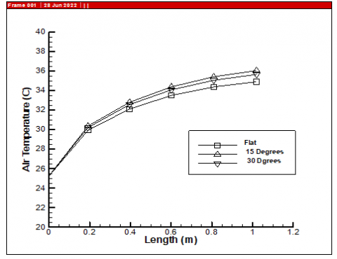
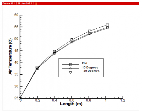
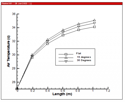
Figures 4, 5 and 6 show the comparison of the variation of the air temperature with length for flat plate, at 15° and 30° degrees at 8 am, 12 pm and 04 pm respectively. Inclination of 15° and 30°, both are higher than flat plate at 8 am and 04 pm because the sun is tilted from the vertical axis before and after midday. While flat plate at 12 pm, is higher compared to those of 15° and 30° angles. This is because the sun's rays are vertical, but for a short time. Thus, the double slope collector is better in increasing the air temperature because the time of the sun's rays is much more tilted than it is vertical.
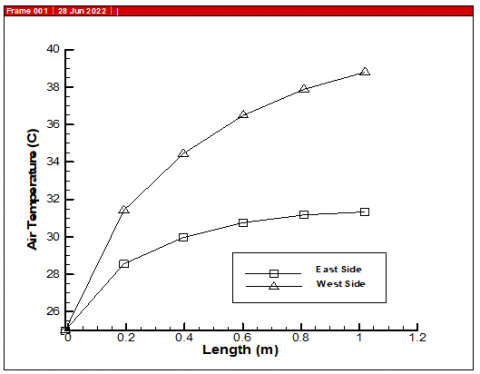
Figures 7 and 8, for plate inclination of 15°, the temperature in the east side at 8 am is higher than the west side, while later after mid-day, the temperature in the west side will be higher than east side, which logical behavior.
Figure 9 displays the exit air temperature variation with time for flat, 15° and 30°. The comparison between the 15°, 30° and flat plate showed that the inclination of 15° is higher than that of 30° from 8am to 11am and from 1pm to 6pm because the sun tilted from the vertical axis before and after midday. So, it will the best radiation reception( absorption) when the angle of inclination was 15. This was evident when measuring the intensity of radiation in the practical part, and it resulted in a rise in the temperature of the absorbing surface and, in turn, the temperature of the air.
Figure 4. Air temperature variation with length at 8 am for flat, 15° and 30°
Figure 5. Air temperature variation with length at 12 pm for flat, 15° and 30°
Figure 6. Air temperature variation with length at 04 pm for flat, 15° and 30°
Figure 7. Air temperature variation with length at 08 am for west and east sides for 15°
Figure 8. Air temperature variation with length at 04 pm for west and east sides for 15°
Figure 9. Exit air temperature variation with time for flat, 15° and 30°
Figure 10 illustrates the contours of temperature were plotted in three- dimensional form, demonstrating temperature gradient along the collector duct at 12 pm. The air passing over the hot surface acquires a portion of the thermal energy, as we notice that the temperatures increase in the direction of the air flow.
Figure 10. Isothermal contours for air for flat absorber at 12pm
Figure 11 shows the flow field in the solar air collectors as 3D at 12pm. The velocity decreased as pointing towards the collector duct walls till becoming zero at the walls. As can be seen from this figure the effect of boundary layer is noticed by the reduction in the velocity in the region that adjacent to the walls of collector.
Figure 11. Flow field for air for flat absorber at 12 pm
In general, it can be noted that the air, while passing through the collector, will increase in temperature upon contact with the heat-absorbing surface, which is heated by the effect of the fall of solar radiation. This will increase the buoyant force in the momentum equation, and thus increase the velocity of air flow inside the collector towards the exit. The air velocity at the walls was zero as a result of the friction between the air and the walls, which was represented by defining the boundary conditions in the momentum equation at the walls. Also, the air velocity was increasing as the air moved away from the walls towards the center due to the effect of the boundry layers, while the air temperature was the highest value near the absorbing wall and also increased towards the exit.
In this study, the effect of double slope solar collector with different angles on the thermal performance of the solar air collector was investigated numerically. The results showed that the effect of double slope collector helps in absorbing sunlight better than the flate plate due to the double slope, which is equivalent to the trackers. The results also showed that the double slope solar collector continued to operate throughout the day through the increase air temperature and its velcity towards the outlet at all times and according to the intensity of solar radiation. The induced air temperatures increase when used the double slope collector, also the thermal performance of air solar collector is enhanced. Double slope can replace the tracking devices used in solar collectors and as found in water distillation devices.
|
G |
generation of kinetic energy, J/m3 s |
|
k |
turbulent kinetic energy, m2/s3 |
|
p |
Local pressure, N/m2 |
|
Q |
solar heat intensity, W/m2 |
|
ST |
source term |
|
T |
temperature, ℃ |
|
Tin |
Inlet air temperature, ℃ |
|
Tf |
mean fluid temperature in channel, ℃ |
|
u, v, w |
velocity components in x, y and z directions respectively, m/s |
|
x, y, z |
Cartesian coordinate, m |
|
Greek symbols |
|
|
ε |
energy dissipation rate per unit mass, m2/s3 |
|
β |
volume coefficient of expansion, 1/K |
|
ρ |
density of air, kg/m3 |
|
μ |
viscosity, N s/m2 |
|
μeff |
effective viscosity, N s/m2 |
|
μt |
turbulent viscosity, N s/m2 |
|
δeff |
effective Prandtl number |
|
δt |
turbulent Prandtl number |
[1] Bejan, A.S., Labihi, A., Croitoru, C., Catalina, T. (2018). Air solar collectors in building use-A review. In E3S Web of Conferences, 32: 01003. https://doi.org/10.1051/e3sconf/20183201003
[2] Abbas, H.M., Jalil, J.M., Ahmed, S.T. (2021). Experimental and numerical investigation of PCM capsules as insulation materials inserted into a hollow brick wall. Energy and Buildings, 246: 111127. https://doi.org/10.1016/j.enbuild.2021.111127
[3] Rostami, S., Abd Hamid, A.S., Sopian, K., Jarimi, H., Bassim, A., Ibrahim, A. (2022). Heat transfer analysis of the flat plate solar thermal collectors with elliptical and circular serpentine tubes. Applied Sciences, 12(9): 4519. https://doi.org/10.3390/app12094519
[4] Amraoui, M.A. (2021). Three-dimensional numerical simulation of a flat plate solar collector with double paths. International Journal of Heat and Technology, 39(4): 1087-1096. https://doi.org/10.18280/ijht.390406
[5] Xu, H., Zhang, C., Wang, N., Qu, Z., Zhang, S. (2020). Experimental study on the performance of a solar photovoltaic/thermal system combined with phase change material. Solar Energy, 198: 202-211. https://doi.org/10.1016/j.solener.2020.01.064
[6] Sardouei, M.M., Mortezapour, H., Jafari Naeimi, K. (2018). Temperature distribution and efficiency assessment of different PVT water collector designs. Sādhanā, 43(6): 1-13. https://doi.org/10.1007/s12046-018-0826-x
[7] Labed, A., Moummi, N., Benchabane, A., Zellouf, M. (2015). Experimental analysis of heat transfer in the flow channel duct of solar air heaters (SAHS). International Journal of Heat and Technology, 33(3): 97-102. http://doi.org/10.18280/ijht.330314
[8] Dawood, N.I., Jalil, J.M., Ahmed, M.K. (2022). Numerical investigation of a window solar air collector with moveable absorber plates. Engineering and Technology Journal, 40(7): 942-950. http://doi.org/10.30684/etj.v40i7.2270
[9] Ong, K.S., Gobi, K., Lim, C.H., Tan, J.C., Naghavi, S., Baljit, S., Wong, S.Y. (2021, December). Experimental investigation on effect of inclination angle of a flat plate solar air collector. In IOP Conference Series: Earth and Environmental Science, 945(1): 012003. https://doi.org/10.1088/1755-1315/945/1/012003
[10] Salih, S.M., Jalil, J.M., Najim, S.E. (2020). Comparative study of novel solar air heater with and without latent energy storage. Journal of Energy Storage, 32: 101751. https://doi.org/10.1016/j.est.2020.101751
[11] Hussein, O.A., Habib, K., Muhsan, A.S., Saidur, R., Alawi, O.A., Ibrahim, T.K. (2020). Thermal performance enhancement of a flat plate solar collector using hybrid nanofluid. Solar Energy, 204: 208-222. https://doi.org/10.1016/j.solener.2020.04.034
[12] Shamsul Azha, N.I., Hussin, H., Nasif, M.S., Hussain, T. (2020). Thermal performance enhancement in flat plate solar collector solar water heater: A review. Processes, 8(7): 756. https://doi.org/10.3390/pr8070756
[13] Abdulmunem, A.R., Jabal, M.H., Samin, P.M., Rahman, H.A., Hussien, H.A. (2019). Analysis of energy and exergy for the flat plate solar air collector with longitudinal fins embedded in paraffin wax located in Baghdad center. International Journal of Heat and Technology, 37(4): 1180-1186. https://doi.org/10.18280/ijht.370428
[14] Blaise K.K., Magloire K.E.P., Prosper G. (2018). Thermal performance amelioration of flat plate solar collector of an indirect dryer, Mathematical Modelling of Engineering Problems, 5(4): 341-347. https://doi.org/10.18280/mmep.050410
[15] Jalil, J. M., Sultan, K. F., Rasheed, L. A. (2017). Numerical and experimental investigation of solar air collectors performance connected in series. Engineering and Technology Journal, 35(3 Part A). https://doi.org/10.30684/etj.35.3A.2
[16] Chabane, F., Moummi, N. (2014). Heat transfer and energy analysis of a solar air collector with smooth plate. The European Physical Journal-Applied Physics, 66(1): 10901. https://doi.org/10.1051/epjap/2014130405
[17] Patankar, S.V. (1980). Numerical Heat Transfer and Fluid flow. Hemisphere, New York, 41-135.
[18] Dawood, N.I., Jalil, J.M., Ahmed, M.K. (2022). Investigation of a novel window solar air collector with 7-moveable absorber plates. Energy, 257: 124829. https://doi.org/10.1016/j.energy.2022.124829
[19] Imran, A.A., Jalil, J.M., Ahmed, S.T. (2015). Induced flow for ventilation and cooling by a solar chimney. Renewable Energy, 78: 236-244. https://doi.org/10.1016/j.renene.2015.01.019
[20] Launder, B.E., Spalding, D.B. (1983). The numerical computation of turbulent flows. Computer Methods in Applied Mechanics and Engineering, 3(2): 269-289. https://doi.org/10.1016/0045-7825(74)90029-2
[21] Haghighat, F., Jiang, Z., Wang, J.C.Y., Allard, F. (1992). Air movement in buildings using computational fluid dynamics. J. Sol. Energy Eng., 114(2): 84-92. https://doi.org/10.1115/1.2929994
[22] Fadhil, A.M., Jalil, J.M., Bilal, G.A. (2022) Thermal investigation of solar collector with variable solar flux using new design sun simulator. The 3rd International Conference on Electromechanical Engineering and Its Applications (ICEMEA-2022) Electromechanical Engineering Department, University of Technology, Baghdad, Iraq.