Aveen T. Mohsin | Banipal N. Yaqob*
© 2022 IIETA. This article is published by IIETA and is licensed under the CC BY 4.0 license (http://creativecommons.org/licenses/by/4.0/).
OPEN ACCESS
The industry is becoming more interested in peripheral pumps because they are inexpensive, have low specific speeds, and are small. One of the more serious problems that may occur with any pump is cavitation. That has a significant impact on pump components, particularly the impeller. This work presents a detailed experimental study on prolonging impeller lifespan under cavitation conditions by studying the effect of impeller surface finishing and coatings on its lifetime. For this purpose, seven impellers, in addition to the original one of the peripheral pump, had prepared and treated. Three impellers with three different levels of arithmetic surface roughness (Ra) were produced using a low-cost and customizable hand grinding procedure. And four impellers have been coated thermally with four different erosion-resistant composite materials. All of the impellers were cavitated for 300 minutes at normal and one at high water temperatures. The result showed that the mass loss percentages with the smallest (Ra) of 0.35µm, and coated with yellow epoxy were 84.86% and 48.50% lower than the original impeller, respectively. Thus, improving the quality of impeller surface finishing, and thermal coatings are excellent method for increasing the impeller's cavitation erosion resistance and thereby extending its lifetime.
cavitation, centrifugal pump, lifetime, peripheral impeller, surface coating, surface roughness
The peripheral or regenerative pump is a kind of dynamic centrifugal pump. The core uses of peripheral pumps have been in the domains of liquid pumping and, in particular, water supply [1]. But significant modifications have occurred and applications have diversified, where its suction and discharge regions are separated by a stripper on the casing. This type of pump is now used for a variety of tasks. They are gaining popularity in the industry due to their inexpensive cost, low specific speed, compact size, and ability to deliver high heads [2]. However, during service, they sometimes failed due to operationally induced problems, which led to a shortcut in the continued operation. Therefore, controlling the state of the pumps is vital to avoid unexpected stoppages, which may lead to the failure of the entire system [3], and one of these problems is cavitation.
Cavitation has a major influence on pump efficiency in centrifugal pumps (CP)s. It reduces pump efficiency, causing a fluctuation in flow rate and discharge pressure [4]. It may also be harmful to the other internal parts of the pumps. Cavitation is caused by two factors. First, high-velocity internal circulation (from high-pressure zone to low-pressure zone) is forced through the clearance between the impeller and the pump casing, resulting in the formation of a low-pressure region in which cavitation can occur. Second, the liquid circulates within the casing of the pump, rapidly heating up. This type is called discharge cavitation [1]. Cavitation has similar effects in both situations. The collapse of bubbles that generates from cavitation occurrence causing a powerful shockwave, making impeller tips and pump casing to wear prematurely. Discharge cavitation can cause the impeller shaft to break in extreme cases.
The main symptoms of occurring cavitation are; blocking [5], noise and vibration [6], acoustic emission [7], degradation, reduction in performance, and bubble formation [8], and finally erosion damage and instability [9]. However, the different symptoms of cavitation were studied and noticed by researchers, but the vast studies focused on noise and vibration as the dominant visualized symptoms.
Several methodologies and approaches were used to examine and investigate the prediction, formation, occurrence, and prevention of cavitation in CPs. Experimental, analytical, and numerical studies were conducted to discover the different aspects of cavitation in pumps. The superiority of the studies was applied experimentally over those who applied analytical or numerical methods. The review of available literature showed that the analytical approaches were applied in the earlier stages of the present field. While technologies, devices, mathematical programs, and abilities have advanced, experimental and numerical [10] methods (e.g., computational flow analysis (CFA) and computational fluid dynamics (CFD)) have been used in recent studies.
In the experimental approaches, different aspects are studied to ensure that the CP will operate optimally under a range of operating conditions like different fluid types and properties [11], nanofluids [12], and viscoelastic fluid [13], pump rotational speed [14], design optimization by studying the impact of blade geometry [15], blade angle, and its numbers [16].
Other factors that were extensively studied by the researchers to detect their influence on cavitation were, piping upstream of the pump suction flange [7], closed loop piping system [1], flow condition [17], and Net Positive Suction Head (NPSH) [18], the motion of ultrasonic cavitation bubble [19] The review of related studies provided that the effect of impeller surface roughness on impeller lifetime under cavitation and different operating conditions in peripheral pumps needed to be studied further, and coating the impeller surface with different cavitation erosion resistance materials before exposing cavitation had not been studied in previous works. The main objectives of this work to cover these gaps, therefore; significant portion of this study devoted to investigate these factors effect on extending peripheral pump impeller’s lifespan through measuring the mass losses rate of the prepared and tested impellers under cavitation conditions as an indicator for impeller operational lifetime. The finding of this project would contribute not only to enhance of lifetime of impeller but also can make the water pumping systems more efficient, by saving the cost of replacing of impeller and lowering the maintenance cost and frequent shutdown of the pump in general.
This paper is organized into four sections: Section 2 explains the experimental setup utilized in this study, and presents the mathematical models and equations used, followed by section 3 which disusing the results and the final section is about conclusions and recommendations for future work.
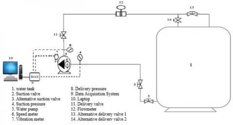
A peripheral pump AP220, a 3-phase motor, 2.2 kW, 4.6 Ampere, (380 to 415) Volts, with a capacity range of (0.3-5.5) m3/h, 2900 rpm, 25.4 mm inlet and outlet diameters respectively, and a maximum head of 100 m, with a brass impeller of 36 blades was utilized in this study, which is widely available in the market. An AC-Drive system is used for controlling and changing the rotational speed of pump motor. The built-up re-circulatory flow loop system consists of a pump, plastic water tank, PVC pipes, connectors, and fitting components. The working process of this built-up recirculation flow loop system is to provide water from the tank to the system and recirculated to the tank again, in order to allows better control over the water temperature and keeping the same level of water in the tank. In the meantime, the pump rotational speed is set at 2900 rpm, and the flow rate, suction and delivery pressure, and impeller weight will be measured before and after each test and each operation time interval while the pump is operating under cavitation conditions. To measure the water flow a turbine flow meter was connected to the pump delivery side, and two pressure transducers were used to measure pump inlet and outlet pressure. Temperature, voltage, and electrical current are among the other physical factors detected, monitored, and measured by various sensors and devices. These measurement sensors and devices helped to directly controlling the variables through holding them constant throughout the study (e.g., the rotational speed of the pump controlled by using AC drive system, the water temperature, and tank water level controlled by thermometers and using re-circulatory flow loop system, and by-pass line used for controlling the opening degree of the valve). Figure 1 shows the schematic diagram of the pump’s flow loop system. The measurement range and accuracy of various sensors used are given in Table 1.
Figure 1. Schematic diagram of experimental setup
Table 1. Measuring devices range and accuracy
|
Measuring device |
Range |
Accuracy |
|
Thermometer |
0…60℃ |
0.5℃ |
|
Clamp meter |
AC/DC current up to 400 A |
2% ± 5 digits |
|
AC/DC voltage up to 600 V |
1.5% ±5 digits |
|
|
Weighing balance |
(0.0001-220) g |
0.0001 g |
|
Pressure transducers |
(-100…300) kPa (suction side) (-100…3000) kPa (Delivery side) |
0.1 kPa |
|
Flowmeter |
(0 – 120) L/min |
±1% |
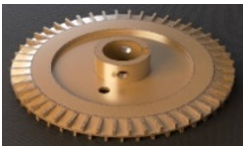
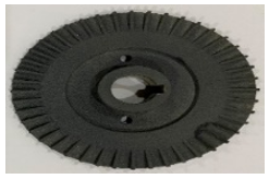
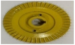
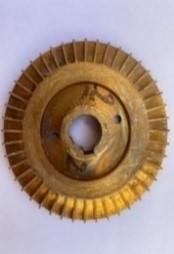
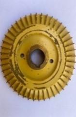
To satisfy the main objective of this study, and investigating the effect of impeller surface roughness and surface coating on its performance, and lifetime under cavitation conditions, seven impellers, in addition to the original impeller, have been treated and prepared. Generally, the impellers used in this experiment had a diameter of 80 mm with a blade thickness of 7 mm, with 36 blades, an outer impeller shaft diameter of 14 mm, and both the pump case inlet and outlet diameter of 25.4mm. The specifications of the eight impellers, including the original impeller, are presented in Table 1. The surface roughness of the radial flow pump impeller is the most important factor in determining the amount of hydraulic flow and friction losses [20]. As shown in the table three impellers with three different levels of arithmetic surface roughness (Ra) of 0.35µm, 1.38µm, and 3µm, in addition to the original one with an arithmetic surface roughness (Ra) of 3µm were produced using a low-cost and customizable hand grinding procedure. The surface roughness of the impellers was measured by using a Surface Roughness Measurement Tester. An additional four impellers have been prepared with four different surface erosion resistance coating composite materials (TiO2Al2O3, Yellow Epoxy, Transparent Epoxy, and NiAl) by using thermal spray coating. The seven modified impellers were installed on the peripheral pump with the original one and were operated under cavitation conditions for 300 minutes in normal water temperature between (15.5-17.5)℃, with only sample number 2 (as listed in Table 2) tested at a high-water temperature of 50℃. The weight of the impellers was measured at different time intervals by using the Sartorius sensitive weight scale to indicate the cavitation erosion mass losses. The cavitation erosion is influenced by the sort of cavitation that forms on the impeller blades as well as the difference between the NPSH required and the NPSH available [21].
Table 2. The specification of the original and modified impellers
|
# |
Impeller photo |
Original weight (g) |
Ra (µm) |
Coated composite material |
|
1 |
178.9666 |
3 |
Original |
|
|
2 |
178.087 |
3 |
-- |
|
|
3 |
177.5813 |
1.38 |
-- |
|
|
4 |
178.8619 |
0.35 |
-- |
|
|
5 |
193.2038 |
-- |
TiO2Al2O3 |
|
|
6 |
178.3043 |
-- |
Yellow-Epoxy |
|
|
7 |
181.4041 |
-- |
Transparent-Epoxy |
|
|
8 |
177.7631 |
-- |
NiAl |
The following formulas were used to compute the pump’s performance parameters, such as flow rate, pump head, Net Positive Suction Head available (NPSHa), hydraulic efficiency, and motor power. The flow rate is given as [21]:
$Q=\forall / t$ (1)
Or
$Q=V \times A$ (2)
The pump head is computed using the energy equation as follows [12].
$H_p=\left(\frac{P_2}{\rho g}+Z_2+\frac{v_2^2}{2 g}\right)-\left(\frac{P_1}{\rho g}+Z_1+\frac{v_1^2}{2 g}\right)-H_L$ (3)
and HL is the total head loss, which is given as [1]:
$H_L=H_f+\sum H_{L M}$ (4)
where, Hf is friction head loss though the length of the piping system, and $\sum H_{L M}$ represent the total of minor losses in valves and fittings. Friction head loss Hf could be found from the Darcy-Weisbeck equation given as [1]:
$H_f=f\left(\frac{L}{D}\right)\left(\frac{v^2}{2 g}\right)$ (5)
The Net Positive Suction Head available (NPSHa) is calculated using the following [22]:
$\mathrm{NPSH}_a=\frac{P_1-P_{\text {vap }}}{\rho g}+\frac{v_1^2}{2 g}$ (6)
The pump efficiency calculated as follows [22]:
$\eta_p=\frac{\rho g Q H}{b h p}$ (7)
where, bhp is the motor break horse power, which found by [22];
bhp=√3×V×I×PF (8)
(Ra) is calculated as the Roughness Average of a surfaces measured microscopic peaks and valleys, expressed in micro meters. The general mathematical expression for arithmetic surface roughness (Ra) is:
$R a=\left(M_1+M_2+M_3+\cdots \cdot M_n\right) / n$ (9)
where, M is the surface roughness measured value and 1, 2, 3, ... n are the number of measured values.
3.1 Surface roughness (Ra) effect on the impeller lifetime prediction
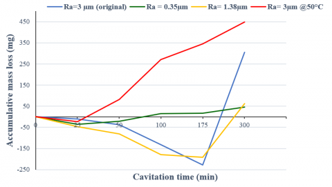
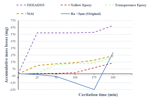
Statistical measures, such as arithmetic surface roughness (Ra), are commonly used to assess surface roughness. The control of erosion and material removal is known to be influenced by surface roughness [20]. For optimizing the impeller lifetime, three impellers with different surface roughness (Ra) (0.35, 1.38, and 3) µm and the original one with (3µm), were operated under cavitation conditions for (300) minutes at a pump rated speed of 2900 rpm. The cavitation test was stopped at various points, and the impellers were weighed with a sensitive balance. The original impeller with the other two impellers with Ra of (0.35 and 1.38) µm were operated under cavitation conditions at a normal water temperature of (15.5-17.5)℃, while the fourth impeller with Ra of 3µm, which has the same Ra of original impeller, was operated under the same cavitation condition but with a water temperature of 50℃. The result of accumulated mass loss of the four impellers as a function of cavitation time is presented in Figure 2. This figure reports that at normal water temperature, after 300 minutes operating under cavitation condition, the original impeller with Ra of 3µm has the greatest mass loss of 304.6 mg, and the impeller with smallest Ra of 0.35µm has the lowest mass loss of 46.1 mg, which is 84.86% less than the original one, followed by the impeller with Ra of 1.38µm by mass loss of 62.1 mg which is 79.6% less. This means that cavitation erosion can be decreased by improving impeller surface quality, thus extending the impeller lifetime with better performance. In other words, cavitation erosion increases by increasing surface roughness. Because surface roughness creates stress inhomogeneities, which promote cavitation, this result was also observed by other researchers [23].
Also, the figure presented that, the temperature of the working fluid has a direct effect on the impeller mass loss, where the impeller with the Ra of 3µm (same as the original one) under water flow temperature of 50℃ has the highest mass loss of 448.8 mg compared to the mass loss of the original impeller with the same Ra but under normal water temperature of (15.5-17.5)℃, which is 304.6 mg. This is due to the fact that the cavitation erosion increased by raising the fluid temperature because of the formation of more bubbles and their collapse [24, 25].
Figure 2. Mass loss for different surface roughness as a function of cavitation time
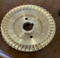
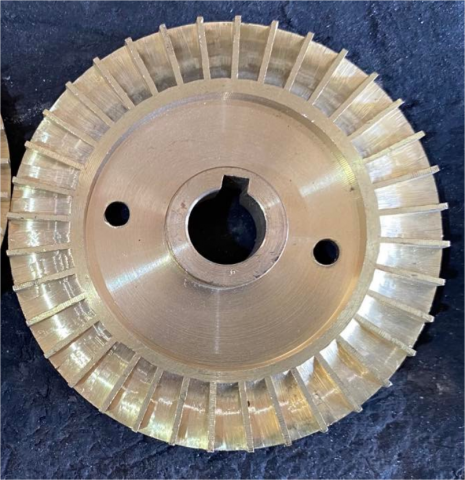
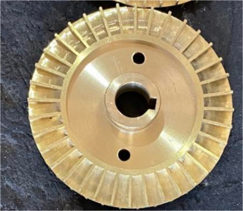
Table 3. Surface polished impellers photo before and after cavitation
|
Impeller (Ra) |
Before |
After |
|
3µm |
||
|
3µm @50℃ |
||
|
1.38µm |
||
|
0.35µm |
Moreover, it can be noticed from the figure that all of the impellers had an incubation stage followed by an accelerated erosion stage. The watershed between the incubation stage and the accelerated erosion stage can be determined depending on factors including surface roughness and grain size, and this conclusion was also found by others researchers [26, 27]. The original impeller, with a high Ra of (3µm) at normal and high-water temperature, was subjected to corrosion and then surface erosion. This because, when an oxidized film scale forms on the impeller surface, it acts as a corrosion barrier [25, 28, 29]. Also, water is one of the worst performers in terms of impeller damage under cavitation conditions, for two main reasons: relatively high density, and phase change behavior. Table 3 shows the effect of cavitation erosion on impellers. In conclusion the impeller lifetime under cavitation can be improved by improving the impeller surface roughness, better finishing surface, longer impeller operation time.
3.2 Surface coating effect on the impeller lifetime prediction
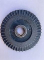
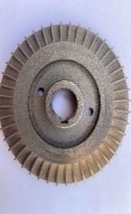
Four impellers with four different erosion resistance composite materials (TiO2Al2O3, NiAl, Transparent epoxy, and yellow epoxy) were coated and prepared by the method of thermal spray coatings in order to test their resistance to cavitation erosion in this study, and compare the result with the uncoated original impeller. The test was carried out to see if coatings were a viable alternative for extending the life of pump impellers. Each impeller was run for 300 minutes at a rated pump speed of 2900 rpm in normal water temperature under cavitation conditions. Figure 3 shows that TiO2Al2O3 coated impeller has the highest mass loss value of 697.1 mg, then followed by (259.5, 240, and 156.8) mg for NiAl, transparent epoxy, and yellow epoxy, respectively. Considering these results with the original impeller result, we figured out that only the TiO2Al2O3 coated impeller has a mass loss value greater than the original uncoated impeller. Otherwise, all of the others have lower values. The mass loss percentages for NiAl, Yellow Epoxy, and Transparent Epoxy as compared to the original impeller are lower by 14.77%, 48.50%, and 21.20%, respectively. These results show that thermally sprayed coatings are an effective technique to improve the cavitation erosion resistance of components, and extending pump impeller lifespan under cavitation condition. Because no substantial changes to the microstructure of substrates and excessive deformation are promoted during the deposition process [30]. The cavitation erosion resistance of TiO2Al2O3 was lower than that of an uncoated original impeller because the nature of the procedure and the processing parameters influence the quality of the coatings produced by thermal spray techniques. Table 4 presents the photos of coated impellers before and after submitting to cavitation.
Figure 3. Mass loss for different surface coating as a function of cavitation time
Table 4. The surface coated impellers photo before and after cavitation
|
Impeller coated |
Before |
After |
|
TiO2Al2O3 |
||
|
NiAl |
||
|
Transparent Epoxy |
||
|
Yellow Epoxy |
(a) Flowrate versus cavitation time
(b) Pressure change versus cavitation time
Figure 4. Performance reduction of the pump with the eight impellers during submitting to cavitation
3.3 Pump performance analysis before, after, and during cavitation
Cavitation is a phenomenon that can arise in any pump and significantly decline the pump's performance [29]. For studying the impact of cavitation on pump performance, after monitoring and gathering extensive data on the pump's performance experimentally, a comparison between the pump performance curve and pump efficiency curve for the eight impellers, including the original one, was made before the pump impeller was exposed to cavitation, after exposing to cavitation and during cavitation for 300 minutes at high rotational speed of 2900 rpm. In Figure 4(a), it is clear that the flowrate of the pump decreased when the pump with eight impellers is subjected to cavitation, this due to the bubbles formed during the cavitation [31]. Also Figure 4(b) shows change in pressure between suction and delivery sides will generally decrease when the pump with eight impellers is exposed to cavitation except for the yellow epoxy coated impellers, which results in a drop in pump performance. Figure 5 presents the pump head versus flowrate (H-Q) and efficiency curves for the eight impellers before and after submitting to cavitation. It can be seen from this figure that the head and efficiency curves of the pump for all the impellers after being exposed to cavitation conditions are degraded except for the yellow epoxy surface coated impeller. This is because the pump was operated with low net positive suction head available, and caused cavitation occurrence especially when the pumping liquid is water. The collapsing cavitation bubbles damaged the impeller surface, and the hollow areas partially clogged the impeller passageways. As a result, reduced pump performance. The performance of the yellow epoxy surface coating has been improved because of a decrease in surface roughness after exposure to cavitation conditions.
(a) Head versus flowrate curve for impellers with varying surface roughness
(b) Efficiency curve for impellers with varying surface roughness
(c) Head versus flowrate curve for impellers with varying surface coatings
(d) Efficiency curve for impellers with varying surface coatings
Figure 5. Performance curves for the eight impellers before and after submitting to cavitation
A comprehensive experimental investigation was carried out regarding prolonging the impeller lifetime and hence improving peripheral pump performance by enhancing the quality of the impeller surface under cavitation conditions. Also, to provide and enhance the current understanding of the influence of cavitation on the performance of the pump. The following are the significant conclusions from each aspect of the current study:
(1) At normal water temperature the impeller with smallest value of Ra (0.35µm) has better cavitation erosion resistance, thus longer impeller lifetime, and in all of the impellers an incubation stage was followed by an accelerated erosion stage. Impellers with higher surface roughness (Ra=3 and 1.38µm) had a longer corrosion incubation stage in normal water temperature than impellers with a low surface finish (Ra = 0.35µm). Also, the quantity of mass loss increased for the same surface finish as the water temperature rose due to the production of additional bubbles and their collapse.
(2) For coating process tests under cavitation conditions, it was discovered that only the TiO2Al2O3 coated impeller has a mass loss value greater than the original impeller; otherwise, all of the others have lower values. This is because the quality of the coatings generated by thermal spray techniques is influenced by the nature of the operation and the processing conditions. These findings suggest that thermally sprayed coatings are an excellent method for increasing the impeller's cavitation erosion resistance and thereby extending its lifespan.
(3) The performance of the pump with the seven different surfaces finished and coated impellers after submitting to cavitation had decreased, except for the yellow epoxy surface coated impeller. The performance of the yellow epoxy surface coated has been improved because of a decrease in surface roughness after exposure to cavitation conditions.
(4) The restrictions and directions for future research as an expansion of the current research: other different erosion resistance materials with different surface coating techniques, different impeller types, geometries, and changing the angle of the impeller can be investigated. Also, different fluids and by adding various nanoparticles to the water at different water temperatures can be used.
The authors would like to thank Erbil polytechnic university research center, Engineer Kosrat Hamid from Dusara company, and Engineer Mustafa Dursun from Premium Proactive Engineering company for their technical support.
|
A |
pipe cross sectional area, m2 |
|
bhp |
break horse power |
|
CFA |
computational flow analysis |
|
CFD |
computational fluid dynamics |
|
Hp |
pump head, m |
|
CP |
centrifugal pump |
|
g |
gravitational acceleration, m.s-2 |
|
I |
current, amp |
|
L |
litter |
|
min |
minute |
|
M |
measured value |
|
n |
number of measured values |
|
NPSH |
net positive suction head, m |
|
Q |
water flow rate, m3.s-1 |
|
Ra |
arithmetic surface roughness, µm |
|
t |
time, s |
|
v |
fluid velocity, m.s-1 |
|
V |
voltage, V |
|
P |
pressure, kg. m-1. s-2 |
|
PF |
power factor |
|
Z |
elevation, m |
|
Greek symbols |
|
|
$\forall$ |
volume of fluid passed, m3 |
|
$\rho$ |
density, kg.m-3 |
|
η |
efficiency, dimensionless |
|
Subscripts |
|
|
1 |
suction side of the pump |
|
2 |
delivery side of the pump |
|
a |
available |
|
f |
Darcy friction factor |
|
L |
loss |
|
vap |
vapor |
|
LM |
minor losses |
|
p |
pump |
[1] Tullis, J.P. (1989). Hydraulics of Pipelines: Pumps, Valves, Cavitation. Transients. John Wiley & Sons. https://doi.org/10.1002/9780470172803
[2] Palgrave, R. (2019). Troubleshooting Centrifugal Pumps and Their Systems. Butterworth-Heinemann.
[3] Adamkowski, A., Henke, A., Lewandowski, M. (2016). Resonance of torsional vibrations of centrifugal pump shafts due to cavitation erosion of pump impellers. Engineering Failure Analysis, 70: 56-72. https://doi.org/10.1016/j.engfailanal.2016.07.011
[4] Wang, K., Wang, C., Xia, C., Liu, H., Zhang, Z. (2018). Experimental measurement of cavitation-induced vibration characteristics in a multi-stage centrifugal pump. Journal of Chemical Engineering of Japan, 51(3): 203-209. https://doi.org/10.1252/jcej.17we191
[5] Sloteman, D.P. (1995). Avoiding cavitation in the suction stage of high-energy pumps. World Pumps, 1995(348): 40-48. https://doi.org/10.1016/S0262-1762(99)80949-3
[6] Nasiri, M.R., Mahjoob, M.J., Vahid-Alizadeh, H. (2011). Vibration signature analysis for detecting cavitation in centrifugal pumps using neural networks. In 2011 IEEE International Conference on Mechatronics, Istanbul, Turkey, pp. 632-635. https://doi.org/10.1109/ICMECH.2011.5971192
[7] Mousmoulis, G., Karlsen-Davies, N., Aggidis, G., Anagnostopoulos, I., Papantonis, D. (2019). Experimental analysis of cavitation in a centrifugal pump using acoustic emission, vibration measurements and flow visualization. European Journal of Mechanics-B/Fluids, 75: 300-311. https://doi.org/10.1016/j.euromechflu.2018.10.015
[8] d'Agostino, L., Salvetti, M.V. (Eds). (2008). Fluid Dynamics of Cavitation and Cavitating Turbopumps. Springer Science & Business Media.
[9] Adamkowski, A., Henke, A., Lewandowski, M. (2016). Resonance of torsional vibrations of centrifugal pump shafts due to cavitation erosion of pump impellers. Engineering Failure Analysis, 70: 56-72. https://doi.org/10.1016/j.engfailanal.2016.07.011
[10] Capurso, T., Menchise, G., Caramia, G., Camporeale, S. M., Fortunato, B., Torresi, M. (2018). Investigation of a passive control system for limiting cavitation inside turbomachinery under different operating conditions. Energy Procedia, 148: 416-423. https://doi.org/10.1016/j.egypro.2018.08.103
[11] Spraker, W.A. (1965). The effects of fluid properties on cavitation in centrifugal pumps. J. Eng. Power., 87(3): 309-318. https://doi.org/10.1115/1.3678264
[12] Bidhandi, M.E., Riasi, A., Ashjaee, M. (2014). The influence of SiO2 nanoparticles on cavitation initiation and intensity in a centrifugal water pump. Experimental Thermal and Fluid Science, 55: 71-76. https://doi.org/10.1016/j.expthermflusci.2014.02.005
[13] Azad, S., Lotfi, H., Riasi, A. (2019). The effects of viscoelastic fluid on the cavitation inception and development within a centrifugal pump: An experimental study. International Communications in Heat and Mass Transfer, 107: 106-113. https://doi.org/10.1016/j.icheatmasstransfer.2019.05.008
[14] Al-Obaidi, A.R. (2019). Investigation of effect of pump rotational speed on performance and detection of cavitation within a centrifugal pump using vibration analysis. Heliyon, 5(6): e01910. https://doi.org/10.1016/j.heliyon.2019.e01910
[15] Ding, H., Li, Z., Gong, X., Li, M. (2019). The influence of blade outlet angle on the performance of centrifugal pump with high specific speed. Vacuum, 159: 239-246. https://doi.org/10.1016/j.vacuum.2018.10.049
[16] Quail, F., Scanlon, T., Stickland, M. (2011). Design optimisation of a regenerative pump using numerical and experimental techniques. International Journal of Numerical Methods for Heat & Fluid Flow, 21(1): 95-111. https://doi.org/10.1108/09615531111095094
[17] ALTobi, M.A.S., Bevan, G., Wallace, P., Harrison, D., Ramachandran, K.P. (2019). Fault diagnosis of a centrifugal pump using MLP-GABP and SVM with CWT. Engineering Science and Technology, an International Journal, 22(3): 854-861. https://doi.org/10.1016/j.jestch.2019.01.005
[18] Lorusso, M., Capurso, T., Torresi, M., Fortunato, B., Fornarelli, F., Camporeale, S.M., Monteriso, R. (2017). Efficient CFD evaluation of the NPSH for centrifugal pumps. Energy Procedia, 126: 778-785. https://doi.org/10.1016/j.egypro.2017.08.262
[19] Qu, W., Xie, Y., Shen, Y., Han, J., You, M., Zhu, T. (2017). Simulation on the effects of various factors on the motion of ultrasonic cavitation bubble. Mathematical Modelling of Engineering Problems, 4(4): 173-178. https://doi.org/10.18280/mmep.040406
[20] Zariatin, D.L., Rahmalina, D., Prasetyo, E., Suwandi, A., Sumardi, M. (2019). The effect of surface roughness of the impeller to the performance of pump as turbine pico power plant. Journal of Mechanical Engineering and Sciences, 13(1): 4693-4703. https://doi.org/10.15282/jmes.13.1.2019.24.0394
[21] Chan, W.K. (1990). Correlation between cavitation type and cavitation erosion in centrifugal pumps. International Journal of Heat and Fluid Flow, 11(3): 269-271. https://doi.org/10.1016/0142-727X(90)90048-G
[22] Al-Obaidi, A. (2018). Experimental and numerical investigations on the cavitation phenomenon in a centrifugal pump. Doctoral Dissertation, University of Huddersfield.
[23] Wang, L., Asomani, S.N., Yuan, J., Appiah, D. (2020). Geometrical optimization of pump-as-turbine (PAT) impellers for enhancing energy efficiency with 1-D theory. Energies, 13(16): 4120. https://doi.org/10.3390/en13164120
[24] Flint, E.B., Suslick, K.S. (1991). The temperature of cavitation. Science, 253(5026): 1397-1399. https://doi.org/10.1126/science.253.5026.1397
[25] Ahmed, S.M. (1998). Investigation of the temperature effects on induced impact pressure and cavitation erosion. Wear, 218(1): 119-127. https://doi.org/10.1016/S0043-1648(97)00290-1
[26] Naguib, N.W.M., Ulrike, D., Johannes, S., Karl-Heinz, Z.G. (2007). The effect of surface finish and cavitating liquid on the cavitation erosion of alumina and silicon carbide ceramics. Ceramics, 51: 30-39.
[27] Stoudt, M.R., Ricker, R.E. (2002). The relationship between grain size and the surface roughening behavior of Al-Mg alloys. Metallurgical and Materials Transactions A, 33(9): 2883-2889. https://doi.org/10.1007/s11661-002-0273-4
[28] Mutahhar, F., Aithan, G., Iski, E.V., Keller, M.W., Shirazi, S.,Roberts, K.P. (2017). Mechanistic modeling of erosion–corrosion for carbon steel. Trends in Oil and Gas Corrosion Research and Technologies, 749-763. https://doi.org/10.1016/B978-0-08-101105-8.00031-0
[29] Karimi, A., Martin, J.L. (1986). Cavitation erosion of materials. International Metals Reviews, 31(1): 1-26. https://doi.org/10.1179/imtr.1986.31.1.1
[30] Santa, J.F., Espitia, L.A., Blanco, J.A., Romo, S.A., Toro, A. (2009). Slurry and cavitation erosion resistance of thermal spray coatings. Wear, 267(1-4): 160-167. https://doi.org/10.1016/j.wear.2009.01.018
[31] Bachus, L., Custodio, A. (Eds.). (2003). Know and Understand Centrifugal Pumps. Elsevier.