Haneen H. Abdulaali* | Samer M. Abdul Ahleem | Abdul Kareem J. Kadhim
© 2022 IIETA. This article is published by IIETA and is licensed under the CC BY 4.0 license (http://creativecommons.org/licenses/by/4.0/).
OPEN ACCESS
This study presents numerical solution by using coupling model between computational fluid dynamic (CFD), and finite element method (FEM) to predicted the temperature distribution through cutting tool. In this study ANSYS/Explicit dynamic used to solve finite element equations in cutting zone. Machining simulations were conducted using Aluminum (AL) and High speed steel (HSS) as a workpeice and tool material respectively. Depth of cut varied from 1.5 mm to 2.5 mm and a cutting speed varied from 6m/s to 10m/s have been considered in the simulations. The CFD model solve by using ANSYS/fluent to find the temperature distribution at the tool surface by using finite volume method. The simulation explained the influence of depth of cut, and cutting speed on cutting temperature. For all simulations, the rake angle is fixed (6°). The rise or reduction in temperature as a result of the various cutting parameters was also estimated and discussed. After solving the problem, it was discovered that the temperature at the tip (tool-work piece contact area) was the highest and gradually decreased towards the surface, and that the results showed a major influence of cutting speed on the temperature generated in the machined models and a very small influence of depth of cut on the workpiece temperature.
finite element method, finite volume method, temperature distribution, CFD model, cutting speed, depth of cut
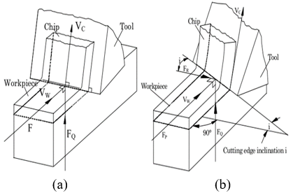
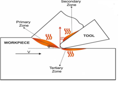
Machining is a significant manufacturing process in industry. The purpose of the machining process is to create surfaces of specific shapes and specifications with a suitable surface finish. Therefore, the chip generated during the machining process will be deformed in addition to their friction with the workpeice and tool, which results in the transformation of 99% of the input energy into heat generated through the friction area, according to Onyechi et al. [1]. Metal cutting mechanics analysis employs two types of cutting: Cutting orthogonally and obliquely. In orthogonal cutting, when a cutting edge that is perpendicular to the direction of relative motion between the tool and the work piece, unnecessary material is removed from the work piece. Since the material removal process is considered to be uniform along the cutting edge in orthogonal cutting, it is a two-dimensional plane strain problem. In oblique cutting, the principal cutting edge is inclined to the direction of the cutting velocity by an inclination angle. as shown in Figure 1 [2]. During the cutting process, there will be three main zones through which heat will be generated: the primary shear zone, where a high plastic deformation occurs through this zone, which leads to the separation of the chip from the workpeice surface and during this process heat will be generated; the secondary deformation zone, which is due to the friction between the cut chip and the tool ; the tertiary deformation zone, which is the result of the tool’s friction with the newly generated workpeice surface, and as shown in Figure 2 the three heat-generating regions [3]. Temperatures in machining operations have also been predicted using a lot of techniques. Majumdar et al. [4] found the temperature distribution during cutting process. They solved multi-dimensional study-state heat equation by using finite element method. They studied numerically the effect of material and geometry of tool on the temperature distribution. They also took into account heat losses as a result of convection losses. The material was free machining steel for work piece, and tungsten carbide for tool. The result showed that by increased cutting speed from 29.6 m/min to 155.4 m/min the maximum temperature rise from 709 K to 1320 K. Carvalho et al. [5] proposed the estimation of the temperature and the heat flux at the chip– tool interface using the inverse heat conduction problem technique. The thermal model is obtained by a numerical solution of the transient three - dimensional heat diffusion equation that considers both the tool and the tool holder assembly. To determine the solution equation the finite volume method is used. Changing in the thermal properties with the temperature and heat losses by convection are also considered. Several cutting tests using cemented carbide tools were performed in order to check the model and to verify the influence of the cutting parameters on the temperature field. Abukhshim et al. [6] reviewed previous research on heat generation and heat dissipation in the orthogonal machining process. In addition, temperature measurement techniques applied in metal cutting are briefly reviewed. The emphasis is on the comparability of test results, as well as, the relevance of temperature measurement method to high speed cutting. New temperature measurement results obtained by a thermal imaging camera in high speed cutting of high strength alloys are also presented. Finally, the latest work on estimation of heat generation, heat partition and temperature distribution in metal machining is reviewed. This includes an exploration of the different simplifying assumptions related to the geometry of the process components, material properties, boundary conditions and heat partition. The paper then proposes some modelling requirements for computer simulation of high speed machining processes. Zhang and Liu [7] developed an analytical model with constant temperature at tool and chip interface of one -dimensional heat transfer in monolayer coated tools to investigate temperature distribution in metal cutting. The explicit form of temperature formulae were obtained by using the Laplace Transform technique and a Taylor series expansion. Calculations conducted for tools of three coatings (TiN, TiC and Al2O3) and two substrates (K0 and P10). The transient temperature distributions have shown that the thermo physical parameters of coating and substrate materials have huge influences on temperature distributions in monolayer coated tools. The analytical solution method has demonstrated that Al2O3 coating has more effective thermal barrier effect than the other two coating materials. The coating thickness also has some influence on temperature distributions in coated tools. Kadirgama et al. [8] studied numerically and experimentally the machining process to find the temperature distribution on the cutting tool. They found the effect of feed rate, cutting speed, and axial depth on the temperature distribution. Box-Bennken design method used to select the experiment conditions. Coolant effect on temperature also investigated. The results showed that optimum value of cutting process with 90° with coolant was at speed 100 m/min, depth 1m, and federate 0.1mm/rev. for cutting process with 70° holder with coolant the optimum conditions was at speed 25 m/min, depth 0.5417 m, and feed rate 0.1mm/rev. Kisku [9] included the numerical method used here is ANSYS. The effect of coated and uncoated cemented carbide cutting tools was modeled using the finite element method. The solution showed that the temperature generated for coated tool is little less in comparison to uncoated cemented carbide insert this shows that the tool life can be increased by placing a coating layer of TiN. Saragi [10] studied the effect of the temperature distribution in tool life and wear using finite element method. By modeling the heat intensity at the cutting zone and shear zone as non-uniform. His work tries to obtain temperature distribution in deformation zones. And the temperature increases on the chip side and tool side along the interface. X, Y, Z dimensional (3D) study heat transfer FEA problem was given boundary conditions that specified temperature, insulated and active conditions. The numerical methodology used here is solid works simulation. Finite element method was used to model the effect of base insulated and base not insulated Cemented carbide cutting tool. From the simulation analytical results; Titanium carbide cutting tool when air cooled maintain constant temperature of 30℃, but cutting tool is insulated the temperature rapidly increases. The Solid works Simulation results show that the tools when its base is convecting has the maximum temperature 130℃ and 115℃ respectively. Onyechi et al. [1] studied analytically and experimentally the temperature distribution in cutting process by using finite element method with ANSYS. They explain the effect of temperature on cutting tool life. They used heat zones method and numerical model based on three - dimension steady state heat transfer. Their results showed that by use cutting tool without insulation that give better temperature distribution and the maximum temperature reach to 400K. Pervaiz et al. [11] used two numerical methods FE, and CFD by coupled between these methods to find temperature distribution. They used Ti6Al4V as a work piece, and uncoated Carbide as a tool material. ANSYS CFX used to simulate the cooling by air. There results showed good potential to fined temperature in cutting zone by using solid fluid interface. The effect of the cutting speed on the temperature distribution. The used 0.1 mm constant depth, and constant feed rate. They used coupling method between thermal and mechanical FE to predict temperature distribution and cutting load. The results showed that cutting force is very depending on friction between workpeice and tool. They found that tool–workpeice interface temperature rise by increasing cutting speed. Kumar et al. [12] developed the finite element model using ABAQUS/Explicit to analyses the temperature effects of turning. A WC tool coated with TiN is considered as tool and AISI 4340 Steel is considered to be the workpeice. Johnson- Cook formulation is employed to model the workpeice and simulations were conducted to examine the temperature distribution, deformation and cutting forces. The results amply demonstrate the influence of machining factors in the process of heat generation and distribution during turning. Ojolo et al. [13] used finite element method with MATLAB to predict the temperature distribution through mild steel cutting process by using Carbide as a cutting tool. They investigated the effect of different parameters such as cutting speed, force (1000<Fs<2000), and rake angles (2° <α <20°). The numerical results showed that maximum temperature reach to 400K at the end of tip. The increases in cutting speed leads to increase the temperature as well as shear force. The results showed the thinner chip rise the temperature at the tool tip. Mohan Reddy et al. [14] studied theoretically machining process of Titanium alloys (Ti-6Al-4V) by using polycrystalline diamond, and cubic boron nitride tool without cooling (dry turning). They used (FE) to predict temperature distribution and cutting force. They change different parameter such as cutting speed, feed rate, and depth of cut. There experiments designed by using the Box-Behnken method. The results showed that feed rate is very effected parameter on cutting temperature whereas depth of cut is most effaced parameter on cutting force. Tu et al. [15] used finite element method to predict the temperature profile in cutting process. They used cubic boron nitride (CBN) and silicon nitride (Si3N4) and compared with titanium nitride (TiAlN) coatings. They studied different parameters such as cutting speed, and tool rake angle. The results showed that temperature direct proportional with cutting speed and invers proportional with rake angle. The temperature of (TiAlN) coatings tool is 28.6% more than CBN-coated tool, so that the use of CBN is give more performance of the tools. Sahoo [16] deals with finite element analysis and prediction of physical parameters during hard turning of AISI4340 steel with ceramic tool insert by considering the effect of cutting parameters i.e. cutting speed (vc), feed rate (f) and depth of cut (d)using DEFORM 3D. The results obtained by simulation will be compared and analyzed with the experimental values. The methodology described here is expected to be highly beneficial to tool developers for complete understanding without performing costly and time consuming experiment. Hussein and Abdullah [17] investigated numerical by using finite element method temperature distribution during cutting process at different zones through cement carbide cutting tool. The temperature interface surface between cutting tool and chip is found by empirical equation. The tool with (12*12*4 mm3) dimensional modeling by using COMSOl. The results showed the temperature distribution through the cement carbide cutting tool. The aim of this study is finding the temperature distribution through cutting tool by using FEM-CFD model. The temperature of chip predicted by ANSYS/Explicit, and by coupling with ANSYS/Fluent.
Figure 1. Types of cutting: (a) Orthogonal cutting, (b) Oblique cutting [2]
Figure 2. Heat generation zones in metal cutting [3]
The cutting tool is the main element in machining operation by which the chip formation and machining performance depend on its sharpness and durability. Many tools have been invented since the early time of machining development until the moment. The cutting tool faces many aggressive conditions during metal cutting such as tool wear, reduction of edges sharpness, high heat generation, and losing durability. The cutting tool must be created by using many hard materials, especially the materials that stand high heat and friction during metal cutting. Many attempts were executed based on experimental or analytical study to enhance the performance of cutting tool such as inserting coating using cooling methods and lubrication of the cutting area to prevent any expected loss in the lifetime of the tools due to the aggressive cutting conditions. In this study, the material of cutting tools is high speed steel. High-speed steel tools occupy the larger place of cutting tool sales owning to its unique physical and mechanical properties that make them good candidates for the production of parts with an optimal combination of high strength, wear resistance, toughness and hardness. These tools could be used from woodworking to machining of hard materials like stainless steel, titanium based alloys, and any other high-grade alloys. A modern cutting tool was invented lately according to German classification of metals (HSS DIN 338) which has unique properties as a result of adding some important metals such as 5% of cobalt to enhance the surface hardness. The chemical composition of HSS DIN 338 tool is mentioned in Table 1 [18]. HSS is the most material that used in manufacturing of drill bits, milling cutters, saw blades, drills, taps, broaches and more. Tools made of high speed steel permanently keep a sharp edge for longer time than other carbon steel tools, and the variety of grades and surface treatments available give options for specialized applications.
Table 1. Chemical composition of HSS DIN 338 [18]
|
Element |
Symbol |
Percentage % |
|
Carbon |
C |
0.85 |
|
Silicon |
Si |
0.3 |
|
Manganese |
Mn |
0.2 |
|
Phosphor |
P |
0.002 |
|
Sulfur |
S |
0.002 |
|
Chromium |
Cr |
3.87 |
|
Molybdenum |
Mo |
4.72 |
|
Nickel |
Ni |
0.18 |
|
Vanadium |
V |
1.75 |
|
Tungsten |
W |
6.09 |
|
Cobalt |
Co |
5 |
|
Ferrous |
Fe |
Remaining |
Table 2 display the properties of the materials used in manufacturing both tool and workpeice. The properties of (Aluminum) are provided by the ANSYS materials library, while the properties of the (High speed steel) were taken from reference [18].
Table 2. Material characteristics of both cutting tool and workpiece [18]
|
Property |
(HSS) tool |
(Aluminum) workpeice |
|
Poisson's Ratio |
0.3 |
0.34 |
|
Density |
8138 kg/m3 |
2710 kg/m3 |
|
Melting Point |
1430℃ |
660.2℃ |
|
Elastic Modulus |
233 GPa |
68.3 Gpa |
|
Shear Modulus |
80 - 105 GPa |
26 GPa |
|
Ultimate Tensile Strength |
1280 MPa |
90 MPa |
|
Hardness |
62 HR |
35.4-60 HR |
|
Specific Heat Capacity |
460 J ̸kg.K |
951 J ̸kg.K |
|
Thermal Conductivity |
41.5 W/m.K |
237.5 W/m.K |
|
Thermal Expansion |
12.6 × 10⁻⁶ /K |
23.5 × 10⁻⁶/K |
3.1 Establishment of 3D finite element modeling
Finite element models are created in ANSYS/Explicit in order to simulate 3D orthogonal machining processes. A model was developed for simulation of temperature distribution in tool-chip interface based on the contact stresses estimated earlier. The models are run as a coupled thermal-mechanical analyses in order to include thermal effects. As cutting occurs, it generates a large amount of heat which cause thermal effects that in turn, largely impact mechanical behavior. The analysis procedure consists of three phases such as pre-processing, solution and post processing. The Pre-processing phase consists of defining geometry, material, mesh and boundary conditions. The solution phase consists of defining analysis settings and convergence. The post processing phase consists of obtaining results.
3.2 Design and modelling
The geometry of machining process was created by using the Solid-work program. A number of objects are created to get the final shape of the geometry with the following procedures:
Figure 3. Model shape
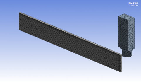
Meshing is made for the tool and work piece by assigning element size or by default meshing size. The meshed body and boundary conditions, show in Figure 4 and Figure 5.
Figure 4. Model mesh
Figure 5. Model boundary conditions
The geometry device shown in Figure 3 consists of a workpeice with a length, height and width of (150 mm) (50 mm) (30mm) respectively. The tool made with rake angle of 6°. Here cutting tool and workpeice considered as flexible body. The analysis has been performed for different depth of cuts and by altering the cutting speed while maintaining a constant feed rates. It can be inferred from the table that three different depth of cuts (1.5 mm, 2 mm and 2.5 mm) have been employed. For these depth of cuts, the cutting speed was (6 m/s, 8m/s and 10 m/s), see Table 3.
Table 3. Model setup details
|
Depth of cut (t) mm |
Cutting speed (v) m/s |
Rake angle (α) |
|
1.5,2,2.5 |
6 |
6o |
|
1.5,2,2.5 |
8 |
6o |
|
1.5,2,2.5 |
10 |
6o |
The ANSYS 2020 R2 program was utilize for modeling and simulation the cutting process in the present study to sub programs have been used to complete the simulation of metal machining first one is explicit dynamic, in this sub program simulate the movement of cutting tool with the depth of feeding and the velocity of cutting process. The FEM technique were used to establish the simulation of cutting process. The temperature generated in the cutting process are a result parameter which in term used to complete the temperature distribution in both workpeice and cutting tool by using the second sub program fluent. Finite element model was developed considering aluminum (Al) as workpeice material and HSS as a cutting tool material. Due to high and constant temperature of chip also it continues contact with cutting tool surface it can be consider a constant temperature body. In the cutting process the tool is move with the constant velocity and the workpeice is fixed as the cutting process is started both the workpeice and cutting tool temperature are increased. Thus for more accurate simulation a natural force convection have been considered in the modeling of case study. ANSYS Fluent which utilized the finite volume technique.
5.1 The influence of cutting speed on workpeice temperature
Figure 6 discuss the variations of maximum temperature that recorded on the workpiece model with respect to cutting speed. It’s noted that the workpiece temperature increased noticeably with increasing of cutting speed at different feed rate. The increase of cutting speed of the tool causes excessive heat generation in the machined models at primary deformation zone (shear plane). This heat is created by the internal friction between the particles of the metal as a result of chip formation at this zone by the cutting tool. The increase of cutting speed of the tool leads to increase the friction between the flank face of the cutting tool and workpiece which leads to create excessive heat at tertiary deformation zone (tool-workpiece interface). Therefore, more heat will be generated in the machined models. The increase of cutting speed of the tool leads to increase the friction between the flowing chip and the cutting tool at secondary deformation zone (chip-tool interface), which leads to rise up the frictional heat at this zone and thus more heat will be transferred to the workpiece from the secondary deformation zone.
Figure 6. The variation of temperature with respect to cutting speed
5.2 The influence of cutting depth on workpiece temperature
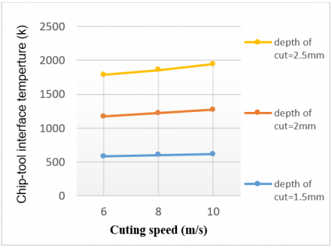
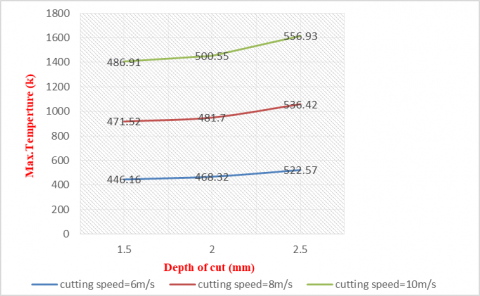
Figure 7 show the change of the cutting temperature obtained in cutting zone as the function of depth of cut with respect to different cutting speed. It can be seen in Figure 7. For the depth of cut 1.5 mm, the recorded temperature is 446.16 k when the depth of cut increases to 2 mm the value of temperature becomes 468.32 k. And when the depth of cut increases to 2.5 mm, the value of temperature becomes 522.57 k. So if the depth of cut increases, the section of chip increases and friction of chip-tool increases what leads to an increase in temperature.
Figure 7. The variation of temperature with respect to depth of cut
5.3 Temperature distributions in the cutting tool
In the cutting process the tool is move with the constant velocity and the workpeice is fixed as the cutting process is started both the workpeice and cutting tool temperature are increased. Thus for more accurate simulation a natural force convection have been considered in the modeling of case study. It considered the coefficient of heat convection for tool and chip is 26 w/m2.k. And for workpeice is 8 w/m2.k.
5.3.1 Temperature contours inside the cutting tool
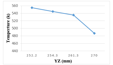
Figure 8 show the temperature gradient inside the cutting tool on YZ plane. It can be seen clearly that maximum temperature appears at the interface of the tool tip then it gradually decrease away from the tool tip.
Figure 8. Show the temperature gradient inside the cutting tool on YZ plane
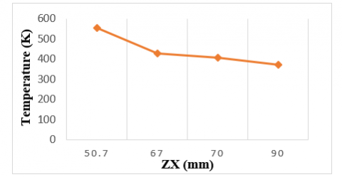
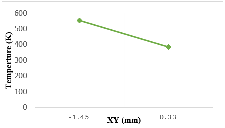
Likewise, it seen this distribution of temperature inside the tool on planes ZX and XY. It proved the temperature is gradually decreases keep away from the heat source. Figures 9 and 10 show graphically the temperature gradient inside the cutting tool on ZX and XY planes.
Figure 9. The temperature gradient inside the cutting tool on ZX plane
Figure 10. The temperature gradient inside the cutting tool on XY plane
5.3.2 Three dimensional Temperature distributions in the cutting tool insert
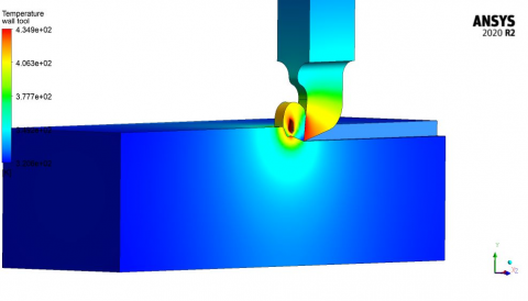
The temperature of cutting tool can be estimated by Ansys/Fluent. Generally, the temperature in the cutting tools is lower than the temperature resided in chips. This can be ascribed to following two aspects. Firstly, the chips experience not only the intensive friction but also the plastic deformation generated by the extrusion of cutting tools. But the cutting tools only undergoes the friction resulted from the chips and work piece due to its higher hardness than workpiece. Additionally, the thermal contact conductance of tool - chip interface affects heat transfer; thus, the cutting heat transferred to the cutting tools is reduced. After applying the boundary conditions on the cutting tool, Figure 11 show the temperature contours of High Speed steel cutting tool and aluminum work material. It is indicated that the maximum temperature appeared at the connection surface between the insert and the workpiece where the heat flux effects directly on the insert. It can be shown that most of the body of cutting holders have temperature equals to 300 K and this means that the heat does not reach all the regions of the holder. It seen that the heat transfer by conduction through the insert and then to the tool holder. The heat transferred by convection from the outer surfaces to the surrounding leads to reduce the temperature of the body of the holder. At the start, the tooltip was warmed by the applied heat flux, and then with the time spending, the thermal energy is dispersed in the tool.
Figure 11. Show the temperature contours of High Speed steel cutting tool and aluminum work material
The present study discusses the effect of cutting parameters such as depth of cut and cutting speed on the temperature generated in cutting tool of High speed steel (HSS) during cutting simulations that based on Finite element /Finite volume analysis. The following points of conclusion have been drawn from this study:
• The cutting tool temperature is found to increase significantly with increase of cutting speed and depth of cut.
• The maximum temperature rise (560.1K) is found when the cutting speed is 10 m/s, depth of cut is 2.5 mm and tool is 6° rake angle. The little temperature rise (411.8K) is found when cutting speed is 6 m/s and depth of cut is 1.5 mm. This is obvious evidence about the significant role of cutting speed and cutting depth in controlling of the amount of temperature that generated on the machined models.
• The maximum temperature were found at the tool tip then it gradually decrease away from the tool tip.
[1] Onyechi, P.C., Benjamin, O., Obuka, N. (2013). Analytical modeling of temperature distribution in metal cutting: Finite element approach. Onyechi, Pius C 1. Oluwadare, Benjamin S 2. Obuk Nnaemeka, 2(4): 17-33. https://doi.org/10.15632/ijret.2014.0304147
[2] Kilicaslan, C. (2009). Modelling and simulation of metal cutting by finite element method. The Graduate School of Engineering and Sciences of İzmir Institute of Technology in Partial Fulfilment of the Requirements.
[3] Islam, C. (2018). A transient thermal model for machining. Thesis, no. October, p. 2018.
[4] Majumdar, P., Jayaramachandran, R., Ganesan, S. (2005). Finite element analysis of temperature rise in metal cutting processes. Applied Thermal Engineering, 25(14-15): 2152-2168. https://doi.org/10.1016/j.applthermaleng.2005.01.006
[5] Carvalho, S.R., Lima e Silva, S.M.M., Machado, A.R., Guimarães, G. (2006). Temperature determination at the chip-tool interface using an inverse thermal model considering the tool and tool holder. Journal of Materials Processing Technology, 179(1-3): 97-104. https://doi.org/10.1016/j.jmatprotec.2006.03.086
[6] Abukhshim, N.A., Mativenga, P.T., Sheikh, M.A. (2006). Heat generation and temperature prediction in metal cutting: A review and implications for high speed machining. International Journal of Machine Tools and Manufacture, 46(7-8): 782-800. https://doi.org/10.1016/j.ijmachtools.2005.07.024
[7] Zhang, S., Liu, Z. (2008). An analytical model for transient temperature distributions in coated carbide cutting tools. International Communications in Heat and Mass Transfer, 35(10): 1311-1315. https://doi.org/10.1016/j.icheatmasstransfer.2008.08.001
[8] Kadirgama, K., Noor, M.M., Rahman, M.M., Harun, W.S.W., Haron, C.H.C. (2009). Finite element analysis and statistical method to determine temperature distribution on cutting tool in end-milling. European Journal of Scientific Research, 30(3): 451-463.
[9] Kisku, R.C. (2011). Modelling of temperature profile in turning with uncoated and coated cemented carbide insert. 107. http://ethesis.nitrkl.ac.in/2501/.
[10] Saragi, E. (2012). Modeling of temperature distribution in TRISO fuel-based on finite element method. AIP Conference Proceedings, 1448(3): 270-274. https://doi.org/10.1063/1.4725464
[11] Pervaiz, S., Deiab, I., Ibrahim, E.M., Rashid, A., Nicolescua, M. (2014). A coupled FE and CFD approach to predict the cutting tool temperature profile in machining. Procedia CIRP, 17: 750-754. https://doi.org/10.1016/j.procir.2014.01.104
[12] Kumar, B.V.R.M., Hemachandra Reddy, K., Vikram Kumar, C.R. (2016). Finite element model based on abaqus / explicit to analyze the temperature effects of turning. International Journal of Applied Engineering Research, 11(8): 5728-5734.
[13] Ojolo, S.J., Yinusa, A.A., Ismail, S.O. (2017). Modelling of temperature distribution in orthogonal machining sing finite element method. Advances in Transdisciplinary Engineering, 6: 427-432. https://doi.org/10.3233/978-1-61499-792-4-427
[14] Mohan Reddy, M., Kumar, M., Shanmugam, K. (2018). Finite element analysis and modeling of temperature distribution in turning of titanium alloys. Metallurgical and Materials Engineering, 24(1): 59-69. https://doi.org/10.30544/323
[15] Tu, L., Xu, F., Wang, X., Gao, J., Tian, S., Yuen, M.F., Zuo, D. (2019). Temperature distribution of cubic boron nitride–coated cutting tools by finite element analysis. International Journal of Advanced Manufacturing Technology, 105(7-8): 3197-3207. https://doi.org/10.1007/s00170-019-04498-0
[16] Sahoo, S. (2019). Review on hard turning using finite element method. Journal of Engineering Innovation and Research, 9(1): 61-68.
[17] ussein, S.G., Abdullah, M.Q. (2020). Finite element analysis of heat flow and temperature distribution inside cutting tool. Journal of Mechanical Engineering Research and Developments, 43(2): 406-414.
[18] Kadhim, A.M., Hassan, A.F., Rishack, Q.A. (2021). The effect of machining parameters and drill point angle on the temperature distribution in AISI 304 stainless steel during dry drilling operation. Basrah Journal for Engineering Sciences, 21(3): 25-33.