Syaiful* | Hukamasidhi Yoel | Nazaruddin Sinaga | Bambang Yunianto | Maria F. Soetanto
© 2022 IIETA. This article is published by IIETA and is licensed under the CC BY 4.0 license (http://creativecommons.org/licenses/by/4.0/).
OPEN ACCESS
Fin and tube is a compact heat exchanger, have been widely used in various engineering fields such as heating, ventilation, air conditioning, and refrigeration systems. An example, indoor and outdoor air-conditioning, the air is used as one of the heat exchanger media. However, over 90% of the total thermal resistance from air to liquid lies on the airside. Therefore, the reduction of thermal resistance should be made to increase heat transfer. This study is intended to investigate the effect of enhancing convex-strip surface to heat transfer and friction characteristic on the heat exchanger. Three-dimensional modeling of the convex fin and the plain fin was conducted on a constant tube temperature of 106℃. Tube with the configuration of the six staggered strands on the odd tube and five rows on the even tube is determined. The velocity variation in the fin gap is assessed under the Reynolds number range between 3,438 to 15,926. The enhancement of four convex-strips around the tube on the fin surface can generate the value of the field synergy angle on fluid flow. The simulation results also show that the improvement of convection heat transfer coefficient value in convex-strip fin with staggered configuration is 15.39% higher than plain-fin.
convection heat transfer coefficient, pressure drop, vortex intensity, synergy angle
Fin and tube is one of the compact heat exchangers that are widely used in the chemical industry, power plants, HVAC, refrigerates, and automotive. Indoor and outdoor air conditioning is one example of fin and tube heat exchangers with air as a cooling or heating medium. Because of the low thermal conductivity of the air, the thermal resistance is high. This high thermal resistance causes the convection heat transfer rate to below, resulting in low efficiency of the heat exchanger. Therefore, increasing the efficiency of the heat exchanger needs to be done by increasing the convection heat transfer rate. Various studies have been carried out to increase the convection heat transfer rate experimentally and numerically. The convection heat transfer rate can be increased by manipulating the air fin side heat transfer design. Various fin designs have been used to increase heat transfer rates such as wavy fin [1-3], slotted fin [4-10], and fin with vortex generator [1, 11-18]. Zhang et al. [1] conducted a study by improvising wavy fin into a humped wavy fin. Humped radius is varied with R=0.3, 0.5 and 0.7 mm. Their simulation results show that the lowest average field synergy angle is humped radius R=0.5 mm. A low field synergy angle shows a higher temperature gradient. In addition, Yu et al. [2] conducted a numerical study of the flow between two wavy fins with low Reynolds numbers. The results of their numerical analysis show that Nusselt numbers increase in proportion to the non-dimensional amplitude of waviness and Peclet numbers. Hong et al. [3] investigated the use of wavy corrugated tubes against heat transfer and flow behavior. Variations are divided into 19 cases, each case with a variation of corrugation amplitude (A), corrugation number (N), corrugation arrangement, corrugation width (W), and different corrugation height (H). Their work shows that the largest performance evaluation criterion (PEC) occurs in the configuration A=5 mm, N=3, W=9 mm, H=1.4 and parallel settings at Re=7500. The configuration states the value of PEC 1, 56 higher than plain-fin use. Meanwhile, Li et al. [4] conducted a study of slotted fin and tube with the addition of longitudinal vortex generators. Numerical simulations are performed on laminar flow with a staggered tube configuration. Their numerical simulations show that the j/(f1/3) factor increases to 15.8% from the baseline. In the study of Kong et al. [5], two types of the slotted fin (continuous slots and alternating slots) are tested numerically to find their effect on the heat transfer coefficient. In their study, slotted fin with an in-line and staggered configuration was studied. The results of their study showed that the heat transfer coefficient in continuous slots fin with staggered configuration was the highest compared to all the variations in alternating fin slots and plain fin. Li et al. [6] investigated experimentally and numerically the performance of the air side of the slotted fin surface of the arc, X, and butterfly types. The analysis shows that the butterfly type slotted fin reduces the domain average synergy angle, thus increasing the temperature gradient. examined the characteristics of a rectangular channel heat transfer with a silt-vent cylinder. Maximum heat transfer performance occurs in the G/D=2.0 gap ratio, where the Nusselt number value increases 17.45%, and the friction coefficient decreases 4.94% from the baseline [7]. Kong et al. [8] conducted a numerical simulation of a flat and slotted fin and tube to investigate the effect on heat transfer and pressure drop. Fifty cases of fin and tube are varied according to longitudinal tube pitch and transverse tube pitches. Their numerical simulation results show that the slotted fin heat transfer coefficient increases 64.96-73.28%, while the pressure drop only increases 39.07-45.68% compared to the flat fin. Deng and Qian [9] revealed the effect of arc-slotted fin cores on the thermal resistance of heat exchangers. Thermal contact resistance (TCR) is the result of making arc-slotted fin. Their results show that TCR has a large negative impact on heat transfer performance and a small impact on decreasing pressure drop. Sun et al. [10] examined the effect of guiding channels and topology optimization on heat transfer performance and the ability to reduce fan power. Guiding channels are done using concave that surrounds the tube, and topology optimization is done by adding emboss. Their results state that guiding channels and optimization topologies dissipate heat, respectively 8.5% and 7.0% higher, and reduce fan power consumption respectively 41.4% and 33.3%. Research on the fin with vortex generator (V G) a lot is done to determine the effect on thermal performance. Lei et al. [11] conducted a numerical study of the VG fin punched delta-winglets to improve their thermal-hydraulic performance. The results of their numerical study show that thermal- hydraulic performance at β=15° shows an increase in Nusselt numbers and a pressure drop of 85.3% and 156%, respectively, from the baseline. The numerical study of the winglet vortex generator delta was carried out by Li et al. [12]. to improve thermal performance. In their study, the height of the vortex generator was varied at the attack angle 30°. Their simulation results state that increasing the height of the vortex generator causes a decrease in thermal resistance. This causes an increase in the heat transfer rate. Meanwhile, the common-flow-up vortex generator produces the best convection heat transfer rate at the 30o attack angle. On the other hand, Song et al. [13] examined curved winglet delta vortex generators in a circular tube-fin heat exchanger. Their research varied the size of the vortex generator geometry, tube pitch, and fin pitch. Their results showed that the value of (j/ƒ)(1/3) increased by 18.79% from the plain fin. Esmaeilzadeh et al. [14] compared the performance of smooth channels, trapezoidal vortex generators, and curved trapezoidal vortex generators. The results of their investigation showed that the Nusselt number on the use of the trapezoidal vortex generator, and the curved trapezoidal vortex generator increased respectively by 8% and 12% from the smooth channel. In addition, the friction coefficients on the trapezoidal vortex generator, and curved trapezoidal vortex generators increased 29% and 48% respectively from smooth channels. Ebrahimi et al. [15] conducted a study of liquid shear (carboxymethyl cellulose) and rectangular winglet vortex generator (RWVG) to increase the heat transfer coefficient. The attack angle and lateral distance of the RWVG were varied in this study. The results of the study stated that the heat transfer coefficient increased by 134.83% from the plain channel. Meanwhile, Välikangas et al. [19] examined herringbone fin heat exchangers to increase the heat transfer coefficient. The results of this study stated that the heat transfer coefficient on fin herringbone with vortex generator increased by 5.23% from fin herringbone without vortex generator. Xu et al. [16] conducted a numerical study on a rectangular channel by adding a vortex generator in the type of half-cylinder, rectangle, straight triangle, isosceles triangle, and inverse straight triangle. From their research, it was found that the half-cylinder vortex generator produced better thermal performance compared to other types of vortex generators. From previous research, Ayutasari et al. [17] conducted an experimental test on rectangular winglet (RWP) and concave rectangular winglet (CRWP) type generators. This experimental test showed that heat transfer coefficients in rectangular winglet (RWP) and concave rectangular winglet (CRWP) type vortex increased 205% and 109%, respectively, from the baseline. Then, Syarifudin et al. [18] have numerically examined rectangular channels using a rectangular winglet vortex generator (RW VG) and concave rectangular winglet vortex generator (VG CRW). VG CRW is varied into one, three, four, and seven lines. The results of this study state that CRW VG increases the heat transfer coefficient better than RW VG. The VG CRW heat transfer coefficient increases by 102% in the Reynolds number Re=364. The proven passive method [1-18] effectively increases the thermal performance of heat exchangers, so Li et al. [12] conducted experimental tests on fin and tube heat exchangers by adding convex-strips around the tube. Their experimental results show that the use of convex-striped fin increases the Nusselt number to 25% higher than the plain fin case. The use of convex-striped fin heightens the friction coefficient to 16% higher than the plain-fin case. The present simulation provides a detailed analysis involving vortex intensity and the principle of synergy between flow velocity and temperature gradient in which such an analysis cannot be found in experiments.
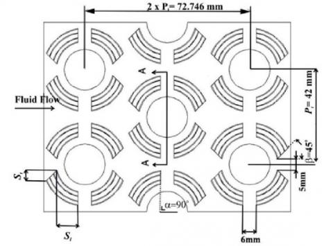
Numerical studies are carried out by simulating 3-D fluid flow in rectangular channels that have been installed fin and tube. In this case, the plain fin is compared to convex-striped fin. Four convex strips were added around the tube with a tube configuration arranged in a staggered 12 rows and six columns. Figure 1 shows the top and side view of the convex striped fin geometry successively. Fin dimensions are specifically seen in Table 1.
(a)
(b)
Figure 1. (a) Top view of convex-striped fin geometry, (b) Side view of convex-striped geometry fin
Table 1. Geometry parameters on convex-striped fin [20]
|
Dc (mm) |
Fp (mm) |
Pl (mm) |
Pt (mm) |
δ (mm) |
Sw (mm) |
Ss (mm) |
Row No. |
|
19.6 |
2.3 |
36.4 |
42 |
0.15 |
4.24 |
9.45 |
11 |
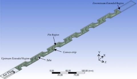
In this numerical analysis, fluid is assumed to be incompressible. Airflow velocities in rectangular channels are varied in the Reynold number range from 3,438 to 15,926. Rectangular channels have dimensions of length (L) 536.5 mm, width (W) 21 mm, and height (FD) 2.3 mm. In the channel, the flow direction is expressed as X, Y, and Z axes, respectively, as the direction of flow, transverse direction, and distance between fins seen in Figure 2.
(a)
(b)
Figure 2. Computational domain and its coordinate system (a) Top view of the computational domain, (b) Isometric view of the computational domain
The dashed line in Figure 2(a) shows the computational domain chosen because the fin geometry has symmetry. The computational domain includes the entire fin surface in an iterative calculation to solve the conjugate heat transfer problem. Figure 2(b) shows the computational domain in isometry, which consists of the extension of the entry area (upstream extended region), fin region, and extension of the downstream extended region. The upstream extended region functions to ensure fluid flow that enters the fully develop channel. At the same time, the downstream extended region is added so that the fluid does not experience reverse flow.
In this study, fluids are assumed to be incompressible with constant physical properties. Flow velocity varied in the Reynolds number range from 3,438 to 15,926 [12]. Because the inlet speed is quite high and the distance between fin is tight, the fluid flow is assumed to be turbulence flow. Fin thickness and fin conduction transfer are included in the calculation. The temperature distribution of the fin surface can be determined by solving the conjugate heat transfer problem in the computation domain [20].
3.1 Governing equation
The governing equation used to solve this case includes.
Continuity equation
$\frac{\partial}{\partial x_i}\left(\rho u_i\right)=0$ (1)
Momentum equation
$\frac{\partial}{\partial x_i}\left(\rho u_i u_k\right)=\frac{\partial}{\partial x_i}\left(\mu \frac{\partial u_k}{\partial x_i}\right)-\frac{\partial p}{\partial x_k}$ (2)
Energy equation
$\frac{\partial}{\partial x_i}\left(\rho u_i T\right)=\frac{\partial}{\partial x_i}\left(\Gamma \frac{\partial T}{\partial x_i}\right)$ (3)
where, ρ (kg/m3) and μ (kg/m.s) each represent air dynamic density and viscosity. Whereas Γ shows the diffusion coefficient as follows:
$\Gamma=\frac{\lambda}{c_p}$ (4)
where, λ and Cp, respectively, are thermal conductivity and specific air heat.
3.2 Boundary conditions
Boundary conditions for the entire surface of the computation domain are described as follows:
3.2.1 At upstream extended region
At inlet boundaries
$u=u_{i n}=$ const, $v=w=0, T=T_{i n}=$ cons (5a)
At the top and bottom boundaries
Velocity condition: periodic condition $u_{\mu p}=u_{\text {down }}$
Temperature condition: periodic condition $T_{u p}=T_{\text {down }}$ (5b)
At the side
$\frac{\partial u}{\partial y}=\frac{\partial w}{\partial y}=0, v=0, \frac{\partial T}{\partial y}=0$ (5c)
3.2.2 At downstream extended region
At inlet boundaries
$\frac{\partial u}{\partial x}=\frac{\partial v}{\partial x}=\frac{\partial w}{\partial x}=\frac{\partial T}{\partial x}=0$ (6a)
At the top and bottom boundaries
Velocity condition: periodic condition $u_{\mu p}=u_{\text {down }}$
Temperature condition: periodic condition $T_{u p}=T_{\text {down }}$ (6b)
At the side
$\frac{\partial u}{\partial y}=\frac{\partial w}{\partial y}=0, v=0, \frac{\partial T}{\partial y}=0$ (6c)
3.2.3 At fin region
At the top and bottom boundaries
Velocity condition: periodic condition $u_{u p}=u_{\text {down }}$
Temperature condition: periodic condition $T_{u p}=T_{\text {down }}$ 7(a)
At side boundaries
$\frac{\partial u}{\partial y}=\frac{\partial w}{\partial y}=0, v=0$ (7b)
At fin surface boundaries
$u=v=w=0, \frac{\partial T}{\partial y}=0$ (7c)
At fin surface boundaries
$u=v=w=0, T=T_w=$ const (7d)
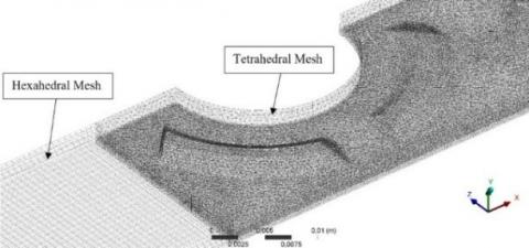
Accuracy in the meshing process is needed to get good results on the value of speed, temperature, and pressure. The hexahedral mesh is used in the upstream extended region and downstream extended region because the area has an uncomplicated geometric shape. In comparison, the fin region is used tetrahedral type mesh because of the more complex geometric shapes. The results of the meshing can be seen in Figure 3. Governing Eqns. (1)-(3) with boundary conditions in Eqns. (5)-(7) is solved by computational fluid dynamics. Numerical simulations are carried out using the k-k turbulent model with a standard wall-function to determine the solution in the area around the fin. The SIMPLE algorithm is used to solve velocity and pressure coupling. Convergence criteria for continuity, momentum, and energy equations must meet requirements less than 10-5, 10-6, and 10-8.
Figure 3. Mesh generation
4.1 Parameter definition
The parameters used in this study are as follows:
Reynolds Number
$R e=\frac{\rho u_m D_h}{\mu}$ (8)
Nusselt Number
$N u=\frac{h D_h}{\lambda}$ (9)
where, $\rho$, um, µ, Dh and λ are respectively density, average fluid velocity, dynamic viscosity, hydraulic diameter, and thermal conductivity of the fluid. h is the convection heat transfer coefficient described by Eq. (10).
$h=\frac{q}{A\left(T_w-T_f\right)}$ (10)
where, q, A, Tw, and Tf are respectively convection fluid heat transfer rates, heat transfer surface area, hot wall temperature, and bulk fluid temperature. Bulk fluid temperature is calculated using Eq. (11).
$T_f=\frac{T_{i n}-T_{\text {out }}}{2}$ (11)
where, Tin and Tout are the temperatures at the inlet and outlet, respectively.
London goodness factor corelation is used to determine thermal and hydrodynamic performance, which is defined as the ratio of Colburn factor (j) and friction factor (f) specified in Eqns. (12) and (13) [21].
$j=\frac{N u}{\operatorname{Re} \operatorname{Pr}^{1 / 3}}$ (12)
$f=\frac{2 \Delta P D_h}{\rho u_m^2 L}$ (13)
where, L is the rectangular channel length, and ∆P is the fluid flow pressure drop passing through the rectangular channel formulated by ∆P=Pin-Pout.
The field synergy principle (FSP) is a method to analyze the degree of improvement of convection heat transfer rates by determining the angle between the speed vector and the temperature gradient. This angle is then called the field synergy angle (θ), which is determined by Eq. (14). U is the velocity vector, and ∇T is the temperature gradient [1, 6].
$\theta=\cos ^{-1}\left(\frac{U \cdot \nabla \mathrm{T}}{|U||\nabla \mathrm{T}|}\right)$ (14)
Song et al. [22] explained that Se is the intensity of dimensionless numbers representing the ratio of inertial forces induced by secondary flow with a viscous force on a normal axis plane. This number is used to define the longitudinal intensity of vortex through Eq. (15).
$S e=\frac{\rho D_h U}{\mu}$ (15)
where, U is the secondary flow velocity characteristic that describes vorticity in the normal axis plane.
$U=D_h\left|\frac{\partial w}{\partial y}-\frac{\partial v}{\partial z}\right|$ (16)
Sex is the average intensity of secondary flow at a small volume. This number is used to define the longitudinal intensity of a local vortex.
$S e_x=\iint_{A(x)}\left|\frac{\partial w}{\partial y}-\frac{\partial v}{\partial z}\right|$ (17)
4.2 Independent grid
Independent grid testing is done to ensure that the numerical simulation results are not affected by the number of grids. In this independent grid test, simulations were carried out on five variations in the number of different grids in the Reynolds number 3.438. This simulation aims to obtain the results of heat transfer coefficients from each number of grids tested with ranges between 1,100,000 to 2,300,000. The grid with the number of elements 2,150,390 was chosen as the independent grid in this study.
Numerical studies of increased heat transfer by adding convex surfaces have been carried out. Several observed phenomena and several influential parameters are discussed in detail.
5.1 Validation
Validation was done by comparing the results of numerical calculations with the results of experiments conducted by Li et al. [12]. Figure 4 shows a comparison of the Nusselt numbers of the experimental and simulation results for the plain and convex-strip cases on the fin and tube heat exchangers with variations in the Reynolds number. In this figure, Nusselt numbers for plain and convex-strip results of the simulation have tendencies similar to the experimental results. While Figure 5 shows a comparison of the friction coefficient of the experimental and simulation results for the plain and convex-strip cases on the fin and tube heat exchangers with variations in Reynolds numbers. Similar tendencies were observed in the friction coefficient values of the simulation and experimental results for the two fin types.
(a)
(b)
Figure 4. Validation of Nusselt numbers in (a) convex-striped fin (b) plain fin
(a)
(b)
Figure 5. Friction factor validation graph in (a) convex-striped fin (b) plain fin
5.2 Effect of convex-strip on flow structure and temperature distribution
To identify the flow structure in detail, a streamlined analysis is carried out in the selected domain at the height of the horizontal plane of 0.4 Fd. To simplify the analysis of flow structures in both cases, the domains analyzed were determined for areas bounded by dashed lines representing other regions, as shown in Figure 6.
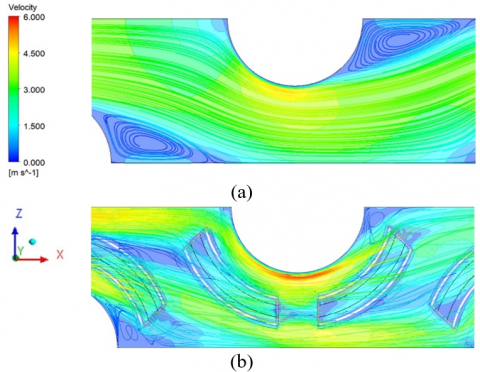
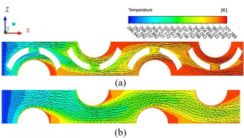
Figure 7 shows a comparison of the flow structure between plain and convex-strip. In the plain case, the flow velocity is seen to be close to zero in the wake area. Syaiful et al. In a previous study, low flow velocity was caused by the presence of circulation flow (secondary flow) [23]. The secondary flow is generated by flow separation because the low speed near the tube wall is not able to overcome the adverse pressure gradient in the rear area of the tube (wake) so that the flow experiences a stall to form reverse flow [24]. Whereas in Figure 7(b), the addition of convex is observed to generate swirl flow. Swirl flow causes the flow to pass through the wake region effectively and eliminate it [25]. As the downstream direction, swirl flow experiences decay at a certain distance because it rubs against the mainstream and experiences viscous dissipation [26].
Figure 6. Selected domain to graph streamline for plain and convex-strip cases
Figure 7. Streamline velocity on fin and tube heat exchangers for (a) plain cases; (b) convex-strip
(a)
(b)
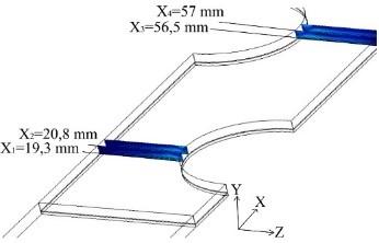
Figure 8. Cross-sectional position of the computational inlet of (a) convex-striped fin; (b) plain fin
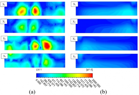
Some cross-sections in certain positions are determined to observe the flow due to convex strips, as shown in Figure 8. The cross-sections are placed at X1=19.3 mm, X2=20.8 mm, X3=56.5 mm, and X4=57 mm from the computational domain inlet such as the study conducted by Song and Wang [27]. Figure 9 shows the contour of vortex intensity, Sex from the two types of the fin in different cross-sections. In general, the intensity of the convex vortex case was observed to be higher than plain in all cross-sections, as seen in Figure 10 due to longitudinal induction of vortex by convex [28]. In comparison, the intensity of the plain case vortex has a lower increase than the convex-strip in all cross-sections. The vortex intensity, in this case, is due to horseshoe vortex, which is generated when the flow passes through the tube [26]. The horseshoe vortex phenomenon is detected through the local temperature around the tube in plain lower cases than convex-strip, as shown in Figure 11 [29]. In the cross-section X2 and X4 for the convex-strip case, the intensity of the vortex weakens compared to the cross-sections X1 and X3. This happens because the longitudinal vortex formed experiences viscous dissipation when the flow moves downstream [30]. Figure 10 shows the 12 peaks longitudinal intensity of the average vortex in front of the tube. A peak is formed because a stronger longitudinal vortex induces flow in the area of stagnation from the tube. Then, the longitudinal intensity of the vortex decreases when the flow passes through the tube. In the convex-strip case, the weak longitudinal vortex intensity is reinforced by the presence of longitudinal induction of the vortex when the flow passes through the convex-strip. Visually, convex-strip generates a counter-rotating vortex, as shown in Figure 12. This longitudinal vortex mixes cold fluid in the middle area of the channel with hot fluid near the wall, thereby increasing heat transfer around the vortex [31]. Meanwhile, the vortex formed around the tube does not affect fluid mixing away from the tube in plain cases. In general, the addition of convex-strip increases the longitudinal intensity of the vortex by an average of 30.63% compared to plain fin. This increase improves the thermal performance of fin and tube heat exchangers.
Figure 9. Contour of vortex intensity, Sex, on heat exchangers (a) convex-strip; (b) plain
Figure 10. Comparison of the spanwise average vortex intensity between plain fin and convex-striped fin at the x/L location
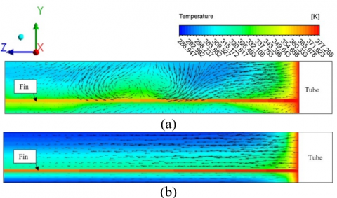
Figure 11. Temperature distribution in the field of 0.4 Fd for cases (a) convex-strip; and (b) plain fin
Figure 12. Temperature contour on cross-section X1 for cases (a) convex-strip; and (b) plain
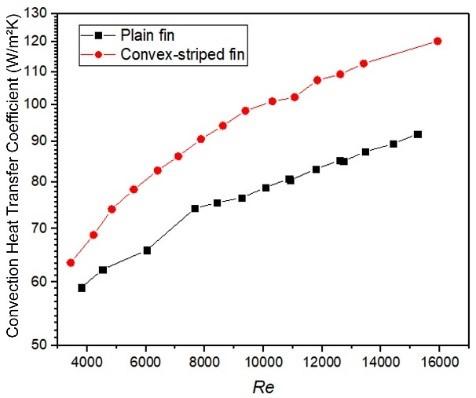
5.3 Effect of convex-strip on heat transfer
Figure 13 shows the comparison of convection heat transfer coefficients, h, convex-strip, and plain cases in different Reynolds numbers. In both types of fin, the convection heat transfer coefficient increases with increasing Reynolds numbers. This is due to the reduction of the thickness of the thermal boundary layer and the increase in fluid mixing when flow velocity has increased [32]. In addition, fin geometry also influences the rate of heat transfer from fin and tube heat exchangers. This is indicated by the higher convection heat transfer coefficient for the convex-strip case compared to the plain case in the same variation of the Reynolds number. The addition of convex-strip increases the heat transfer rate in three ways. First, convex-strip gives rise to the instability of the centrifugal force of the flow that generates a longitudinal vortex [33]. The longitudinal vortex mixes hot fluid in the boundary layer with cold fluid in the free stream area. This mixture increases the convection heat transfer rate. Second, the convex strip removes the flow recirculation area [19]. as shown in Figure 7. Heat transfer increases from the tube to the flow when the recirculation area is reduced. Third, the convex strip causes the mainstream to experience acceleration downstream due to the narrowing of the channel between the convex strip and tube. This results in an increase in a temperature gradient in the area, so that it has an impact on the improvement of the heat transfer rate [34]. The results of this numerical simulation show that the convection heat transfer coefficient in the convex-strip case is 15.39% higher than the plain case.
Figure 13. Heat transfer coefficient on plain fin and convex-striped fin for Reynolds numbers
5.4 Effect of convex-strip on pressure distribution and pressure drop
Figure 14 shows the pressure distribution at the Reynolds number 3.438 according to the horizontal plane 0.4 Fd. In the figure, the pressure range difference in the plain case is observed to be lower than in the convex-strip case. This shows the pressure drop in the case of plain lower than convex-strip. As in the previous study of Syaiful and Bae [23], the pressure drop in the plain case was lower in all Reynolds numbers, as shown in Figure 15. This phenomenon is caused because there is no surface protrusion that blocks the flow [19]. Whereas in the convex-strip case, the flow passes through the channel with a narrower cross-sectional area than the plain case. Cross-sectional constriction results in an increase in vortex strength and a reduction in the recirculation zone [35]. This resulted in a significant increase in pressure in the tube stagnation area as shown in Figure 14(b). The use of convex also increases pressure drop in all ranges of Reynolds numbers. Pressure drop increases with increasing air velocity [25, 36]. High flow rates with large inertia result in greater pressure when the flow hits the tube [37]. From this study, it was found that the use of convex-strip increased the pressure drop twice compared to plain fin.
Figure 14. Pressure distribution in the horizontal plane 0.4 Fd for heat exchangers (a) plain; (b) convex-strip
Figure 15. Pressure drop on plain fin and convex-striped fin for Reynolds number
5.5 Effect of convex-strip on London goodness factor (j/f)
London goodness factor (j/f) is a parameter used to evaluate the overall hydrodynamic thermal performance of fin and tube heat exchangers [38]. Figure 16 shows a comparison of the j/f ratios of convex-strip and plain cases in various Reynolds numbers.
Figure 16. London goodness factors on plain fin and convex-striped fin
From Figure 16, it is found that the London value of the goodness factor for convex strips is higher than the plain case for all Reynolds numbers. However, the j/f ratio for plain cases considers the decreasing tendency to be smaller than convex-strip with increasing Reynolds numbers. This is because pressure losses in the convex-strip case are greater than in the plain case [25, 39]. For the plain case, the blocking effect on the flow is smaller than in the convex-strip case. However, the convex-strip case has a higher heat transfer coefficient compared to the plain case. As shown in Figure 16, the fin and tube heat exchanger with a convex-striped fin has the best comprehensive heat transfer and fluid flow performance [4]. In the Reynolds number 3,000 to 16,000, the London goodness factor value for the convex-strip case is 7.50% higher than the plain case. From this numerical study, it was found that the convex-striped fin is a type of fin with good performance for use in fin and tube heat exchangers.
5.6 Effect of convex-strip on field synergy principle
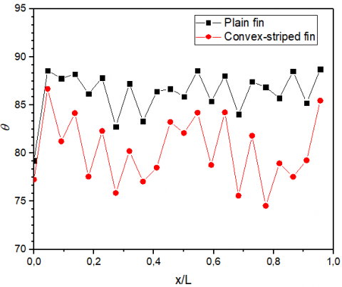
Figure 17. Field synergy angle plain and convex-strips cases in the x/L field for Reynolds numbers of 3,438
Figure 18. Average field synergy angle of plain and convex-strips to Reynolds number
FSP is a method used to identify the increase in heat transfer rates in the flow that has been studied by Guo et al. [40]. Guo stated that the decrease in the angle of intersection between the velocity vector and the temperature gradient indicates an increase in heat transfer. Figure 17 shows the local synergy angle field for the convex-strip and plain cases in the Reynolds number 3,438. From this graph, it is found that the synergy angle field in the convex-strip case is lower than the plain case in all cross-sections x/L. This also occurs in all variations of the Reynolds number, as shown in Figure 18. Minimum peak points for convex-strip and plain cases were found respectively at 78.08° and 81.08° for cross-sections x/L=0.77, and 0.27. The average synergy angle for convex-strip and plain cases is 78.08° and 81.08° in the Reynolds number 3.438. Through some of these explanations, it was found that convex-strips can reduce synergy angle greater than plain. This is because convex-strip can generate a longitudinal vortex stronger than the plain case, as shown in Figure 12. In general, the average synergy angle in the convex-strip case is 6.63% higher than the plain case.
Numerical simulations of fin and tube heat exchangers in the convex-strip and plain cases have been carried out to investigate the effect of convex-strips on the characteristics of heat transfer and pressure drop. The conclusions that can be drawn from this study are as follows.
(1) Convex-strip around the tube results in an increase in convection heat transfer coefficient. The increase in the convection heat transfer coefficient in all variations of the Reynolds number for the convex-strip case is 15.39% greater than the plain case.
(2) The results of this study found that convex-striped fin is a type of fin with good performance for use in fin and tube heat exchangers. In the Reynolds number 3,000 to 16,000, the London goodness factor value for the convex-strip case is 7.50% higher than the plain case.
(3) The synergy angle in the convex-strip case is lower than the plain case. The average synergy angle for convex-strip and plain cases is 78.08° and 81.08° in the Reynolds number 3.438. In general, the synergy angle in the convex-strip case is 6.63% lower than the plain case.
It is mandatory to have conclusions in your paper. This section should include the main conclusions of the research and a comprehensible explanation of their significance and relevance. The limitations of the work and future research directions may also be mentioned. Please do not make another abstract.
This work was supported by the Faculty of Engineering (Fundamental Research, DIPA 2022), Diponegoro University. The authors are grateful to all research members, especially Lab. of Thermofluid of Mechanical Engineering of Diponegoro University Indonesia, Lab. of Aerospace Engineering Department of Bandung State Polytechnic, Indonesia.
|
A |
Total heat transfer area (m2) |
|
Ac |
Minimum flow area (m2) |
|
b |
Distance of rectangular winglet (m) |
|
B |
Channel width (m) |
|
c |
Convex fin |
|
cp |
Fluid specific heat (J/(kgK)) |
|
Dc |
Tube outer diameter (m) |
|
Dh |
Hydraulic diameter (m) |
|
f |
Friction factor |
|
Ft |
Fin width (m) |
|
h |
Convection coeff. (W/m2K) |
|
H |
Channel height (m) |
|
L |
Flow length (m) |
|
N |
Amount of control volume |
|
Nu |
Nusselt Number |
|
P |
Pressure (Pa) |
|
Pl |
Longitudinal distance of tube (m) |
|
Pt |
Transversal distance of tube (m) |
|
∆P |
Pressure drop (Pa) |
|
Pr |
Prandtl Number |
|
Q |
Heat capacity (W) |
|
Re |
Reynold Number |
|
Sex |
Local longitudinal vortex intensity |
|
T |
Temperature (K) |
|
∆T |
Average bulk temperature (K) |
|
u |
Velocity in x direction (m/s) |
|
uin |
Frontal velocity (m/s) |
|
v |
Velocity in y direction (m/s) |
|
Vm |
Average velocity at Amin (m/s) |
|
w |
Velocity in z direction (m/s) |
|
Greek symbols |
|
|
µ |
dynamic viscousity (Pa s) |
|
ρ |
density (kg/m3) |
|
λ |
thermal conductivity (W/(mK)) |
|
θ |
field synergy angle (°) |
|
ϕ |
computational domain |
|
Г |
diffusion coeff. |
|
Ʌ |
winglet aspect ratio |
|
α |
angle of the transversal convex tip to x axis |
|
β |
angle of the longitudinal convex tip to x axis |
|
Subscripts |
|
|
in |
inlet parameter |
|
m |
average value |
|
out |
outlet parameter |
|
w |
wall |
|
cs |
convex-strip |
|
pl |
plain |
|
VG |
Vortex Generator |
[1] Zhang, X., Wang, Y., Li, M., Wang, S., Li, X. (2017). Improved flow and heat transfer characteristics for heat exchanger by using a new humped wavy fin. Applied Thermal Engineering, 124: 510-520. https://doi.org/10.1016/j.applthermaleng.2017.06.068
[2] Yu, D., Jeon, W., Kim, S.J. (2017). Analytic solutions of the friction factor and the Nusselt number for the low-Reynolds number flow between two wavy plate fins. International Journal of Heat and Mass Transfer, 115: 307-316. https://doi.org/10.1016/j.ijheatmasstransfer.2017.08.025
[3] Hong, Y., Du, J., Wang, S., Huang, S.M. (2017). Heat transfer and flow behaviors of a wavy corrugated tube. Applied Thermal Engineering, 126: 151-166. https://doi.org/10.1016/j.applthermaleng.2017.07.135
[4] Li, J., Wang, S., Chen, J., Lei, Y.G. (2011). Numerical study on a slit fin-and-tube heat exchanger with longitudinal vortex generators. International Journal of Heat and Mass Transfer, 54(9-10): 1743-1751. https://doi.org/10.1016/j.ijheatmasstransfer.2011.01.017
[5] Kong, Y.Q., Yang, L.J., Du, X.Z., Yang, Y.P. (2016). Effects of continuous and alternant rectangular slots on thermo-flow performances of plain finned tube bundles in in-line and staggered configurations. International Journal of Heat and Mass Transfer, 93: 97-107. https://doi.org/10.1016/j.ijheatmasstransfer.2015.10.008
[6] Li, H., Wang, H., Yao, M., Zhang, L., Gu, H., Nie, J. (2015). PIV and thermal-vision experimental and numerical investigation on the airside performance of slotted fin surfaces. International Journal of Heat and Mass Transfer, 82: 568-580. https://doi.org/10.1016/j.ijheatmasstransfer.2014.11.039
[7] Wang, J., Wang, C. (2016). Heat transfer and flow characteristics of a rectangular channel with a small circular cylinder having slit-vent vortex generator. International Journal of Thermal Sciences, 104: 158-171. https://doi.org/10.1016/j.ijthermalsci.2016.01.006
[8] Kong, Y.Q., Yang, L.J., Du, X.Z., Yang, Y.P. (2016). Air-side flow and heat transfer characteristics of flat and slotted finned tube bundles with various tube pitches. International Journal of Heat and Mass Transfer, 99: 357-371. https://doi.org/10.1016/j.ijheatmasstransfer.2016.04.002
[9] Deng, J., Qian, Z. (2017). Simplified analysis of thermal contact resistance on arc-slotted fin core. Applied Thermal Engineering, 125: 266-284. https://doi.org/10.1016/j.applthermaleng.2017.06.143
[10] Sun, C., Lewpiriyawong, N., Khoo, K.L., Zeng, S., Lee, P.S. (2018). Thermal enhancement of fin and tube heat exchanger with guiding channels and topology optimisation. International Journal of Heat and Mass Transfer, 127: 1001-1013. https://doi.org/10.1016/j.ijheatmasstransfer.2018.08.093
[11] Lei, Y., Zheng, F., Song, C., Lyu, Y. (2017). Improving the thermal hydraulic performance of a circular tube by using punched delta-winglet vortex generators. International Journal of Heat and Mass Transfer, 111: 299-311. https://doi.org/10.1016/j.ijheatmasstransfer.2017.03.101
[12] Li, X.Y., Li, Z.H., Tao, W.Q. (2018). Experimental study on heat transfer and pressure drop characteristics of fin-and-tube surface with four convex-strips around each tube. International Journal of Heat and Mass Transfer, 116: 1085-1095. https://doi.org/10.1016/j.ijheatmasstransfer.2017.09.076
[13] Song, K., Xi, Z., Su, M., Wang, L., Wu, X., Wang, L. (2017). Effect of geometric size of curved delta winglet vortex generators and tube pitch on heat transfer characteristics of fin-tube heat exchanger. Experimental Thermal and Fluid Science, 82: 8-18. https://doi.org/10.1016/j.expthermflusci.2016.11.002
[14] Esmaeilzadeh, A., Amanifard, N., Deylami, H.M. (2017). Comparison of simple and curved trapezoidal longitudinal vortex generators for optimum flow characteristics and heat transfer augmentation in a heat exchanger. Applied Thermal Engineering, 125: 1414-1425. https://doi.org/10.1016/j.applthermaleng.2017.07.115
[15] Ebrahimi, A., Naranjani, B., Milani, S., Javan, F.D. (2017). Laminar convective heat transfer of shear-thinning liquids in rectangular channels with longitudinal vortex generators. Chemical Engineering Science, 173: 264-274. https://doi.org/10.1016/j.ces.2017.07.044
[16] Xu, Z., Han, Z., Wang, J., Liu, Z. (2018). The characteristics of heat transfer and flow resistance in a rectangular channel with vortex generators. International Journal of Heat and Mass Transfer, 116: 61-72. https://doi.org/10.1016/j.ijheatmasstransfer.2017.08.083
[17] Ayutasari, A., Soetanto, M.F., Siswantara, A.I., Bae, M.W. (2017). Thermo-hydrodynamics performance analysis of fluid flow through concave delta winglet vortex generators by numerical simulation. International Journal of Technology, 8(7): 1276-1285. https://doi.org/10.14716/ijtech.v8i7.706
[18] Syarifudin, I., Soetanto, M.F., Bae, M.W. (2018). Numerical simulation of heat transfer augmentation in fin-and-tube heat exchanger with various number of rows of concave rectangular winglet vortex generator. In MATEC Web of Conferences, 159: 02012. https://doi.org/10.1051/matecconf/201815902012
[19] Välikangas, T., Singh, S., Sørensen, K., Condra, T. (2018). Fin-and-tube heat exchanger enhancement with a combined herringbone and vortex generator design. International Journal of Heat and Mass Transfer, 118: 602-616. https://doi.org/10.1016/j.ijheatmasstransfer.2017.11.006
[20] He, Y.L., Chu, P., Tao, W.Q., Zhang, Y.W., Xie, T. (2013). Analysis of heat transfer and pressure drop for fin-and-tube heat exchangers with rectangular winglet-type vortex generators. Applied Thermal Engineering, 61(2): 770-783. https://doi.org/10.1016/j.applthermaleng.2012.02.040
[21] Qasem, N.A., Zubair, S.M. (2018). Compact and microchannel heat exchangers: A comprehensive review of air-side friction factor and heat transfer correlations. Energy Conversion and Management, 173: 555-601. https://doi.org/10.1016/j.enconman.2018.06.104
[22] Song, K.W., Tagawa, T., Chen, H.H., Zhang, Q. (2019). Heat transfer characteristic if concave and convex curved vortex generators in the channel of plate heat exchanger under laminar flow. International Journal Heat Mass Transfer, 137: 215-228. https://doi.org/10.1016/j.ijthermalsci.2018.11.002
[23] Syaiful, G.R., Bae, M.W. (2016). Attack angle effect of concave delta winglet vortex generator on heat transfer augmentation in fin-and-tube heat exchanger for EGR cooler application by numerical simulation. In FISITA 2016 World Automotive Congress, pp. 26-30.
[24] Buyruk, E., Johnson, M.W., Owen, I. (1998). Numerical and experimental study of flow and heat transfer around a tube in cross-flow at low Reynolds number. International Journal of Heat and Fluid Flow, 19(3): 223-232. https://doi.org/10.1016/S0142-727X(97)10027-3
[25] Chimres, N., Wang, C.C., Wongwises, S. (2018). Effect of elliptical winglet on the air-side performance of fin-and-tube heat exchanger. International Journal of Heat and Mass Transfer, 123: 583-599. https//doi.org/10.1016/j.ijheatmasstransfer.2018.02.079
[26] Huang, R.F., Hsu, C.M., Lin, W.C. (2014). Flow characteristics around juncture of a circular cylinder mounted normal to a flat plate. Experimental Thermal and Fluid Science, 55: 187-199. https://doi.org/10.1016/j.expthermflusci.2014.03.012
[27] Song, K., Wang, L. (2016). Effects of longitudinal vortex interaction on periodically developed flow and heat transfer of fin-and-tube heat exchanger. International Journal of Thermal Sciences, 109: 206-216. https://doi.org/10.1016/j.ijthermalsci.2016.06.011
[28] Han, H., Wang, S., Sun, L., Li, Y., Wang, S. (2019). Numerical study of thermal and flow characteristics for a fin-and-tube heat exchanger with arc winglet type vortex generators. International Journal of Refrigeration, 98: 61-69. https://doi.org/10.1016/j.ijthermalsci.2018.11.009
[29] Xu, Y., Islam, M.D., Kharoua, N. (2017). Numerical study of winglets vortex generator effects on thermal performance in a circular pipe. International Journal of Thermal Sciences, 112: 304-317. https://doi.org/10.1016/j.ijthermalsci.2016.10.015
[30] Lu, G., Zhou, G. (2016). Numerical simulation on performances of plane and curved winglet type vortex generator pairs with punched holes. International Journal of Heat and Mass Transfer, 102: 679-690. https://doi.org/10.1016/j.ijthermalsci.2018.11.009
[31] Ke, Z., Chen, C.L., Li, K., Wang, S., Chen, C.H. (2019). Vortex dynamics and heat transfer of longitudinal vortex generators in a rectangular channel. International Journal of Heat and Mass Transfer, 132: 871-885. https://doi.org/10.1016/j.ijheatmasstransfer.2018.12.064
[32] Ebrahimi, A., Roohi, E., Kheradmand, S. (2015). Numerical study of liquid flow and heat transfer in rectangular microchannel with longitudinal vortex generators. Applied Thermal Engineering, 78: 576-583. https://doi.org/10.1016/j.applthermaleng.2014.12.006
[33] Syaiful, Sugiri, G., Soetanto, M.F., Bae, M.W. (2017). Effect of concave rectangular winglet vortex generator on convection coefficient of heat transfer. In AIP Conference Proceedings, p. 030025. https://doi.org/10.1063/1.4968278
[34] Lu, G., Zhou, G. (2016). Numerical simulation on performances of plane and curved winglet type vortex generator pairs with punched holes. International Journal of Heat and Mass Transfer, 102: 679-690. https://doi.org/10.1016/j.ijthermalsci.2016.06.024
[35] Singha, S., Sinhamahapatra, K.P. (2010). Flow past a circular cylinder between parallel walls at low Reynolds numbers. Ocean Engineering, 37(8-9): 757-769. https://doi.org/10.1016/j.oceaneng.2010.02.012
[36] Li, H.Y., Liao, W.R., Li, T.Y., Chang, Y.Z. (2017). Application of vortex generators to heat transfer enhancement of a pin-fin heat sink. International Journal of Heat and Mass Transfer, 112: 940-949. https://doi.org/10.1016/j.ijheatmasstransfer.2017.05.032
[37] Zhang, Q., Qin, S., Ma, R. (2016). Simulation and experimental investigation of the wavy fin-and-tube intercooler. Case Studies in Thermal Engineering, 8: 32-40. https://doi.org/0.1016/j.csite.2016.04.003
[38] Salleh, M.F.M., Mohammed, H.A., Wahid, M.A. (2019). Thermal and hydraulic characteristics of trapezoidal winglet across fin-and-tube heat exchanger (FTHE). Applied Thermal Engineering, 149: 1379-1393. https://doi.org/10.1016/j.applthermaleng.2018.12.098
[39] Jin, M., Fang, J., Zhan, L., Liu, H. (2015). Performances of heat transfer and fluid flow in the shell and tube heat exchanger with novel sextant fan baffles. In International Conference on Advances in Energy, Environment and Chemical Engineering, pp. 122-125. https://doi.org/10.2991/aeece-15.2015.25
[40] Guo, Z.Y., Li, D.Y., Wang, B.X. (1998). A novel concept for convective heat transfer enhancement. International Journal of Heat and Mass Transfer, 41(14): 2221-2225. https://doi.org/10.1016/S0017-9310(97)00272-X