Mohammed Gh. Mohammed Kamil* | Muna S. Kassim | Raid A. Mahmood
© 2022 IIETA. This article is published by IIETA and is licensed under the CC BY 4.0 license (http://creativecommons.org/licenses/by/4.0/).
OPEN ACCESS
The steam condensation process has been experimentally investigated in an air-cooled condenser (ACC). The ACC has been designed and built using a flattened cross-section horizontal tube. The flattened tube has an internal dimension of 102 mm x 12 mm with 4030 mm length. A range of vacuum operating conditions are applied to operate the ACC. In the experiments, parameters such as vacuum pressure, saturated temperature, wall tube temperature, rate of heat transfer, and local average steam heat transfer coefficient have been considered along the flow direction with the variation of cooling water temperature. The experimental results revealed that the steam saturated temperature and the related pressure decrease with the reduction of the cooling water temperature, and the temperatures of the upper and lower parts of the horizontal flattened tube. The results also showed that the local steam condensation heat transfer coefficient decreases along with the direction of the flow, but it there is incrementing with the decreasing of saturated steam temperature at a certain range of cooling water temperature.
steam condensation, distribution of temperature, vacuum condition, internal flattened tube, condenser absolute pressure
Nowadays, the A-frame air-cooled condenser (ACC) has received much attention to be used in industry, especially in thermal electric power plants, because of the issue of water shortage. It typically saves 99% of the water required by a once-through system [1]. The use of the A-frame of ACC.s has increased considerably in the last ten years [2]. Hence, it is essential to understand the heat transfer process and its thermal performance. Generally, many studies have considered and investigated the two-phase flow in different geometries and different orientations using different approaches such as [3-8]. Basically, the heat transfer coefficient and temperature distribution inside the tube are the main parameters that need to be considered. Circular cross-section tubes are utilized in most of these applications [9]. However, some different tube geometries need to be considered to obtain a clear understanding of the thermal performance and ideal operating conditions. Some studies have suggested and reported some of the non-circular tube geometries such as rectangular cross-section [10], elliptic cross-section [11], and flattened cross-section tubes [3, 12] that can be used in the air-cooled steam condenser.
The condensation phenomenon is a two-phase flow because it involves the simultaneous mobility of a liquid and vapour phase inside a pipe. For example, steam is frequently introduced into a tube as a single-phase vapour, and as the latent heat of vaporization is removed to the cooling system, liquid condensate forms, establishing a two-phase flow. Meanwhile, the two-phase flow behaviour and flow patterns inside the tube condenser have been investigated and considered to obtain high performance considering some parameters such as two-phase flow patterns and its behaviour [12-14]. In addition, some other parameters such as non-uniform temperature profiles, the mal-distribution of airflow, sensibility to wind impacts that can be considered to obtain an ideal thermal performance were reported by some studies [13-19]. Through the condensation process in a horizontal tube, when the vapour's velocity is low, the structures of the flow pattern are controlled by the shear and gravity force. The film of condensation forms around the tube's upper perimeter, flows down to the tube's lower part, and accumulates. Therefore, the flow pattern models can be classified as wavy and stratified flow. The conduction heat transfer is common throughout the film at the top of the tube [20]. Thus, condensation is frequently nouned as film condensation, and it can be analyzed using the classic Nusselt theory [21]. Dobson and Chato [20] submitted a new model of heat transfer which are related to the two-phase structure such as Stratified flow, wavy flow, wavy -annular flow, annular flow were including both the convective and film-wise condensation inside circular tubes. Thome et al. [22] submitted a model of heat transfer for predicting the condensation process through tubes having a certain diameter that has been tested on numerous refrigerant fluids. The model proposed two methods for heat transfer in the condensation process that occurred inside the tubes, where film condensation in the upper circumference and convective condensation in the lower circumference of the tubes. By using several kinds of refrigerant fluid, the experimental data [20-25] shown that when the refrigerant mass flow rate and vapour quality rise, the average condensing heat transfer coefficient increases. In some circumstances, though, different results are reached. Shah [26] submitted a new method of correlations to predict the heat transfer coefficient, which was published previously [27], which was examined with various fluids such as refrigerant, hydrocarbon, and water. These modified correlations depend on heat transfer regimes set according to boundaries represented by equations given by Shah [26]. The modified correlations are in good convention with a database corresponding to analytical solutions for Nusselt number that covers most turbulent flows to the laminar flow cases. The database used to verify the validity of the correlation include many types of fluid such as water, refrigerants, and organics that condensing in inside tubes with vertical, horizontal, and downward inclined orientation. Du et al. [28] found that the heat transfer coefficient of steam condensation inside a copper tube remains virtually constant with the increasing steam velocity at the tail of the tube, which has a diameter of 25 mm and temperature difference equal to two degrees between the saturated steam the coolant media. OˊDonovan et al. [29] submitted a thermal analysis to determine the outputs of erecting an ACC in concentrated solar power. Steam condenser temperature and correspondence pressure have been measured as a function of fan speed, which varied (changing the air volumetric flow rates) at steam mass flow rates. The outcomes illustrate that at a range of steam mass flow rates and constant ambient temperature, the steam condenser temperature and correspondence pressure decrease as the fan speed is increased. Sereda et al. [30] introduced an experimental study to assess the heat transfer during the condensation process of freons R22 and R407C have a saturated condensing temperature of 40℃ in a smooth horizontal tube has an internal diameter of 17 mm, while the range of mass velocity was from 6 to 57kg/m2s and the quality of vapour from 0.95 to 0.23. The authors presented a CFD simulation through the heat transfer of condensing vapour of R22 freon to the system of cooling water by a cylinder that has a thick wall. The CFD model was evaluated using a practical experiment, which revealed that the results agreed with an error range of 7 to 20%. The obtained results improved the prediction of effective HTCs for vapour condensation, taking into account the effect of condensate flow in the tube's bottom half on heat transmission. Pusey et al. [31] evaluated the steam condensation experimentally at low mass velocities (less than 5 kg/m2.s) within an inclined copper tube has an inner diameter of 17.00 mm and 400 mm length in order to ensure effectiveness in the optimum design selection of air-cooled passive heat exchangers. The steam is admitted to the test tube at a pressure of 0.1 MPa and quality of 0.93, 0.54, and 0.26. A closed-loop cooling water system with circulatory and turbine flowmeters to measure the flow rate and regulate heat removal from the test section. The results showed, that regardless of steam quality, the condensation HTC rose by over 15%. Furthermore, the structure of two-phase throughout the steam condensation was stratified across the entire range of the inclination angle (from the horizontal to the vertical); we detected no transitions to annular flow that had been observed in earlier researches utilizing the hydrophilic refrigerants.
Recently, many studies focus on numerical simulations to study the phenomenon of condensation, which provided additional perspectives and information that could not be determined experimentally [15]. Abadi et al. [32] simulated the condensation of R134 inside a smooth inclined tube having a diameter of 8.38 mm and 1488 mm in length. The effects of mass flux, quality of vapour and angle of inclination are studied on the condensation heat transfer coefficients. The VOF technique, in conjunction with Lee's model, was validated as an effective method for analyzing the condensation of the refrigerant. Furthermore, the simulation results were compared with an experimental database, and a high degree of agreement with the experimental data was observed. Deng et al. [33] examined the length of condensation, the thickness of condensate liquid film and the interface shear in the condensation process experimentally. The author considered the variation of parameters such as Reynold number of the cooling air and the mass flux of vapour to investigate. The author also considered visualization of the flow in reflux condensation. Based on numerical simulation results, a number of recommendations for experiments and operation of the flow in tubes with an upward direction were suggested. Padoin and Soares [34] modelled the condensation of steam in circular pipes with certain diameters and 2 m length to optimize industrial design units. The simulation of water vapour condensation allows for the assessment of pumping requirements and best insulation practices. The VOF technique, in conjunction with Lee's model, was employed as an effective method for analyzing phase change phenomena. The modelling results observed that the behaviour of water vapour quality during the condensation process has a liner trend behaviour at 343.15 K and an exponential decline in the steam quality at 293.15 K.
Although there are many studies which consider the steam condensation process using different techniques, there are insufficient information about the stream condensation in a horizontal flattened tube considering the vapour pressure and the mass flow rate of cooling fluid and its temperature. Therefore, this study provides experimental investigation for the heat transfer characteristics of steam condensation process in a horizontal flattened tube under vacuum operating conditions. This study also provides real database and clear understanding about the performance of air-cooled condenser structured by horizontal flattened tube.
2.1 Experimental apparatus
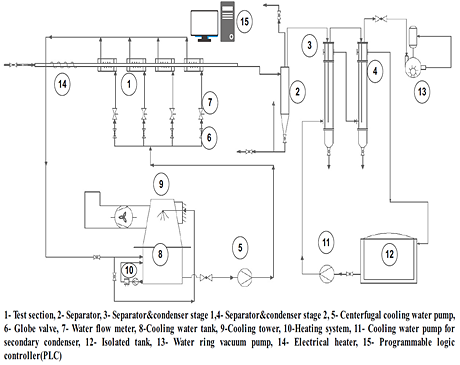
Special facility to operate the two-phase flow in a horizontal flattened tube was designed and fabricated. Figure 1 presents a schematic of the apparatus for the two-phase flow of steam condensation and heat transfer experiment using a horizontal flattened cross-section tube.
(a)
(b)
Figure 1. Apparatus facilities (a) schematic diagram (b) photograph of the apparatus
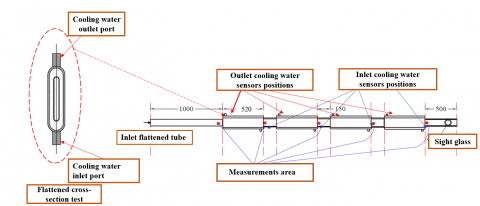
The main test facility consists of a condensation test section which has a flattened cross-section, a cooling water system, a main steam supply pipe, a water condensate separator vessel, secondary separator-condensers segments and a water ring vacuum pump to extract the non-condensable gases and to make the vacuum status during the experimental tests. The loop of steam generation is composed of an oil-fired tube boiler, which has a design/operating pressure of 10/7 bar with a capacity equal to 3000 kg/h. During the experiments, steam pressure was controlled using a pressure regulator to minimize the pressure of supplied steam which enters to the test rig. A steam trap system was installed to drain the condensated water that may generate in the connections and fittings. An electrical heater is installed to heat the steam before entering the test section to confirm that the steam is saturated. The cooling water storage tank is attached with an electrical heater with a 3000 W capacity to supply the cooling water at a certain temperature. The return line (hot water) is injected into the top of the tank through a spray nozzle and mesh to broke the water droplets, which they cold by air that forced by a fan having regulating switch. The centrifugal pump supplies cooling water at a certain temperature to feed the annular cooling jackets to release the heat of the steam in accordance with the counter-flow heat exchanger. In order to control and regulate the flow rate of cooling water for each jacket, four Chlorinated Poly Vinyl Chloride (CPVC) globe valves were installed before each flow meter, which is used to measure the volumetric flow rate of cooling water before entrance of the jackets. Figure 2 and Table 1 show the details of the test section including the positions of sensors and the specifications, respectively.
(a)
(b)
Figure 2. Condenser flattened test tube, (a) measurement area from the inlet test tube, (b) Cooling Water Jacket (CWJ) from the inlet test tube
Table 1. Test section tube specifications
|
Test section |
Material |
Dimensions |
|
Flattened inner tube(steam) |
Carbon steel |
102 mm height * 12 mm width |
|
Annular flattened tube(water) |
Carbon steel |
154 mm height * 42 mm width |
|
Length of tube |
|
4030 mm |
The condensate water and the remaining steam in the test section flow into the separator device tank. The condensate water accumulated in the bottom section of the separator tank due to force of gravity, while the remaining steam flows to secondary vertical separator condensers stages 1 and 2, where the secondary cooling water system completely condenses the steam. The data of the experiment was saved on computer using Siemens software after all of the measuring equipment were connected to a Programmable Logic Controller (PLC). The experimental conditions covers range of temperature and mass flow rate based on the limitation of the experiments. Table 2 lists the operating conditions for the current study.
Table 2. Conditions for experiments
|
Conditions |
|
|
Average inlet steam mass flow rate |
17.41 kg/h |
|
Inlet steam quality |
1 |
|
Volumetric Inlet cooling water |
8 L/min |
|
Inlet cooling water temperature |
68.28, 54.72, 49.17, 44.88, 39.30, 26.66℃ |
2.2 Measurement kits
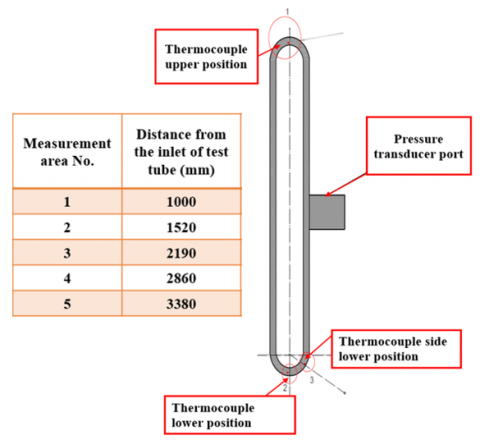
Measurement devices utilized in the experiments are pressure transmitter to measure the vacuum pressure inside the condensation flattened inner tube, thermocouples for the measuring of the internal wall of the inner flattened tube temperature, resistance temperature detectors (RTD) for inlet and outlet cooling water temperature, vortex flowmeter for inlet steam mass flow rate and rotameter to measure the inlet cooling water for each cooling water jacket. Table 3 list the specification of the main instrument. Five measurement areas as shown in Figure (2a) through the direction of the condensation flow inside the flattened inner tube. Each area has a width of 150 mm from the inner flattened condensation tube to access the measurement devices. Figure 3 shows the positions of the thermocouples where mounted on the internal wall of the flattened condensation tube.
Table 3. Instruments specifications
|
Name |
Type |
Range |
|
Pressure |
Wika 10-A |
-1 to 0 bar |
|
Temperature |
K-type |
0 - 400℃ |
|
Temperature |
Pt-100 |
0 -100℃ |
|
Steam vortex flowmeter |
Yantai Auto Instrument C. |
0-200 kg/h |
|
Water rotameter |
ZYIA Instrument C. |
4-36 L/min |
According to the instrument's manufacturing data, the measures' systematic uncertainty was considered in the experiments. In the experiments, three factors were measured directly: temperature, mass flow, and pressure. Parameters h, Q were estimated on the basis of measured parameters, with Moffat's proposed technique of analysis [35]. Table 4 lists the experimental uncertainties according to Moffat's proposed technique of analysis.
Figure 3. Instruments positions on inner flattened tube
Table 4. The uncertainties of parameters
|
Parameters |
Uncertainties |
|
Pressure Transducer |
±0.52 kPa |
|
Steam mass flow rate |
±1.5% |
|
Cooling water flow rate |
±4% |
|
Thermocouples steam temperature |
±2.5℃ |
|
RTD cooling water temperature |
±0.29℃ |
|
Height of flattened tube |
±0.5 |
|
Width of flattened tube |
±0.25 |
|
Rate of heat rejected |
±8% |
|
Steam condensation heat transfer coefficient |
±10% |
2.3 Processing of data
The total rate of cooling water heat transfer for each cooling water jacket Qcw was determined experimentally from.
$Q_{c w}=m_{cw}^{.} C_{p c w}\left(T_{c w o}-T_{c w i}\right)$ (1)
The properties of cooling water were determined at the mean cooling water temperature as shown below:
$T_{m}=\frac{T_{c w i}+T_{c w o}}{2}$ (2)
Considering there are no heat losses to the environment, the heat flux in each water jacket was calculated by
$q=\frac{Q_{c w}}{A_{s c}}$ (3)
The steam condensate flattened inner tube surface area can be found from [36]:
$A_{s c}=L_{w j a c k} *\left[2 *\left(t u b e_{h}-t u b e_{w}\right)+\pi\left(t u b e_{w}-2 t u b e_{t}\right)\right]$ (4)
Due to the difference in the steam temperature, which is about half of a degree between the inlet and the outlet of steam condensation flattened inner tube, the average steam temperature was used to calculate the local average of the steam heat transfer coefficient, which can be expressed as below:
$T s=\frac{T_{s p 1}+T_{s p 5}}{2}$ (5)
$h i=\frac{q}{\left(T s_{-} T_{\text {w.ave. }}\right)}$ (6)
where, $T_{\text {w.ave. }}$ represent the local average internal flattened wall surface temperature as below:
$T_{\text {w.ave. }}=\frac{\sum_{n} T_{w n}}{n}$ (7)
The steam quality at the outlet of each cooling water jacket is calculated is distinct as:
$x_{i}=1-\left(\frac{\sum Q_{c w i}}{m_{s}^{.} \lambda_{f g}}\right)$ (8)
3.1 Pressure and temperature effect
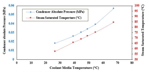
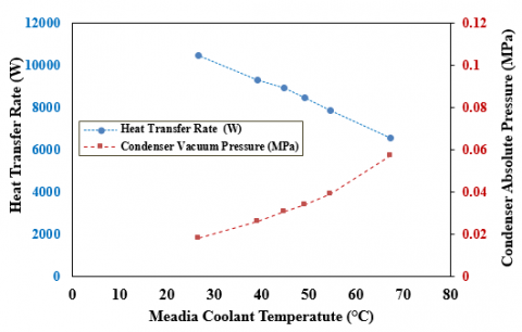
The measured fluctuation in air-cooled condenser temperature and pressure with the varying cooling water temperature at a constant steam mass flow rate of 17.41 kg/h is depicted in Figure 4, respectively. The results in Figure 4 show that the cooling water temperature change substantially affects the condenser steam-side conditions. The temperature and pressure of the steam are decreased when the cooling water temperature is reduced. That means, the design of air-cooled condenser can manage the exit conditions of a steam turbine. Thus, it will increase the energy extracted from the steam in the steam turbine if the cooling media temperature decrease, which will increase the electrical power generation.
In the thermal power plant, steam is utilized to rotate the steam turbine connected to the generator part to generate electricity.
After converting the energy of the steam to kinetic energy, it should be condensed to water to reduce water consumption. In order to maximum benefit from the energy of the steam, requires existed efficient evacuated system to remove the air and non-condensable gases, which can be done by a vacuum pump or ejectors as a first stage of the evacuation system, in addition to coolant media has certain characteristics as a second stage of the evacuation system. To increase and maintain the vacuum condition for the system, be conditional on the temperature and the mass flow rate of the cooling media (water) system.
Figure 4. Coolant media temperature impact on condenser absolute pressure and corresponding saturated temperature
3.2 Temperature distribution for inner surface
The priority is to analyze the thermal performance of steam condensation flow in a horizontal flattened tube in the test rig by measuring distributions of temperature at the upper and lower parts of the inner surface for the flattened steam condensation tube.
(a) (b)
(c) (d)
(e) (f)
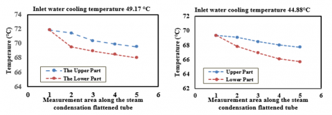
Figure 5. Temperature distribution for the inner surface along the flattened tube at steam mass flow rate 17.41 kg/h
Figure 5 show the distributions of internal surface tube temperature with various inlet cooling water temperatures at steam inlet mass flow rate 17.41 kg/h.
The temperature of the inner surface continuously decreases along the flattened test tube, which is started from position number 1, situated at 1000 mm from the inlet of the tube, and ends in position number 5 with all cases that the inlet water cooling temperature had been varied from 67.28℃ to 26.66℃. For all experimental cases, a notable decrease in the upper inner surface temperature was observed, especially between position one and position two, because of the small thickness of the condensing water that covers the inner surface of the flattened test tube. In comparison, the slope of the temperature line declines after position number two due to the increase of the forming water condensate film on the internal walls of the condensation tube, which makes as a barrier as a result of steam velocity drop along with the condensation. The upper inner surface temperature has dramatically downward when the inlet cooling water temperature was 26.66℃. That because of the great temperature difference between the saturated steam temperature and the cooling water. subsequent most of the steam was condensed at 2860 mm from the inlet of test tube. At the same time, the temperature in the lower part of the inner surface wall tube was significantly reduced along the bottom of the tube, where the slope of the temperature line increment with the increasing of the temperature difference between the saturated steam and the cooling water. On the other hand, when the cooling water temperature decrease, the saturated steam temperature decrease; thus, the shear force of the steam increase, which leads to an increase in the velocity of the accumulated water condensate and an increase in the heat transfer rate.
3.3 Effect of heat transfer
Table 5 lists the rate of heat transfer of each cooling water jacket at a range of inlet coolant media temperature. The rate of heat rejected from the steam is increased with the decrease of cooling water temperature, which is influenced by the temperature difference. The rejected heat of steam was transferred through the cooling water jackets (CWJ) number 1, 2 and 3 along the test tube as illustrated in Figure 2b from the inlet of the test tube which the amount of heat dissipated were convergent, while the heat rejected in cooling water jacket number 4 is less to other jackets due to the steam's velocity and quality decrease along the steam condensation process in the flattened tube.
Figures 6 (a and b) presents the total rate of heat transfer with condenser absolute pressure and saturated steam temperature at different coolant media temperatures when the steam mass flow rate of 17.41 kg/hr.
Table 5. Steam heat reject at a range of inlet cooling water temperature
|
Temp. of C.W. |
67.28℃ |
54.72℃ |
49.17℃ |
44.88℃ |
39.30℃ |
26.66℃ |
|
Jacket no. 1 |
1643.11 |
2043.97 |
2157.41 |
2220.88 |
2441.67 |
2652.05 |
|
Jacket no. 2 |
1625.07 |
2048.98 |
2200.23 |
2274.81 |
2423.64 |
2649.89 |
|
Jacket no. 3 |
1694.42 |
2063.80 |
2217.01 |
2280.62 |
2373.56 |
2678.68 |
|
Jacket no 4 |
1426.33 |
1699.83 |
1870.71 |
2132.95 |
2050.52 |
2482.74 |
|
Total heat rejected (Watt) |
6388.94 |
7856.59 |
8445.36 |
8909.26 |
9289.39 |
10463.37 |
(a)
(b)
Figure 6. Total heat transfer rate (a) with condenser absolute pressure, (b) with steam saturated temperature
The total rate of heat transfer increases significantly with the decrease of cooling water temperature. This happens due to the increase in the temperature difference between the saturated steam and cooling water, which acts as a force of driving for heat transfer, thus vastly enhancing the rate of heat transfer in the heat exchanger area, in addition to the velocity of steam which is considered increasing under vacuum conditions where the temperature of steam saturation is more sensitive to pressure.
3.4 The quality of the steam through the condensation process
In the horizontal tube, the condensation process is affected by shear and gravitational forces that have the dominant influence on the flow patterns. If the velocity of vapour is high, then the shear force is dominant, so the flow knows as an annular flow. When the velocity of the vapour is decremented, the type of flow converts to wavy- stratified or stratified flow, where the steam is condensed on the inner surface wall of the tube and, due to gravitational force accumulated on the lower part of the tube. A shown in Figure 7 the quality of steam out from each cooling water jacket is clearly decreased along the steam condensation process in the horizontal flattened tube due to heat transfer to cooling water. While the quality of the steam out from each cooling water jacket is decremented when the cooling water temperature decline due to the rising of the heat transfer in each water jacket as a result of the increase in temperature difference between steam and cooling water. When the cooling water temperature decrement, that leads to a decrease in the saturated steam temperature. The physical properties of the steam are affected by saturated temperature. The density and viscosity are decreased with the decreasing of saturated steam temperature. Thus, the velocity of the steam increase, which leads to an increase in the shear force of the flow. Therefore, the water condensate film thickness decrease in the upper part of the tube; hence the heat transfer rate increase along the condensation process in the tube. On the other hand, the increase of steam velocity so aggravating the fluctuation of the water condensate film. This aids in the improvement of heat transmission.
Figure 7. The quality of the steam outlet from each cooling water jacket
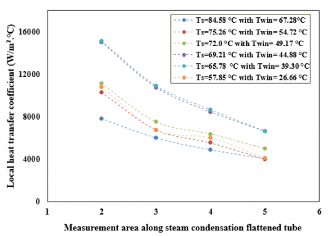
3.5 Local heat transfer coefficient
The local heat transfer coefficient at steam mass flow rate 17.41 kg/hr and range of cooling water temperature (57.28- 26.66)℃ are shown in Figure 8. Clearly, the heat transfer coefficient decrease along the steam condensation flattened tube due to the velocity and the quality of the steam, which diminish through the steam condensation process inside the flattened tube. On the other hand, the steam's local heat transfer coefficient increased slightly at the same measurement areas was found along the flattened condensation tube for the range of cooling water from 67.28℃ to 39.30℃ due to the increasing temperature difference between the saturated steam and cooling water. When the cooling water temperature decrease, the saturated steam temperature decline; thus, the density and the viscosity of the steam are decreased, which leads to an increase in the velocity of steam that raises the shear force between liquid condensate film and the steam subsequently minimizes the thickness of condensate film. Also, increase the momentum that will transfer from steam to condensate film. While at cooling water temperature of 26.6℃, the local steam heat transfer coefficient has weakened even though the increase in the rate of heat rejected which as shown by the authors [37], the rate of increase in Nusselt number diminishes at higher Reynolds numbers although the increasing of air-side heat transfer coefficient where used as a coolant media.
Figure 8. Local heat transfer coefficient at different cooling water temperature
The characteristics of heat transfer for steam condensation in flattened cross-section tube under vacuum condition has been examined experimentally. The distributions of parameters such as vacuum pressure with related saturated temperature, the behaviour of inner surface wall tube temperature, the rate of heat transfer, and local steam heat transfer coefficient are demonstrated along the flow direction with the variation of inlet cooling water temperature (from 67.28℃ to 26.66℃) at steam mass flow rate of 17.41 kg/h. In vacuum conditions, the saturated steam temperature is widely sensitive to the related pressure. As a result, steam condensation flow resistance has a considerable impact on the saturation temperature of the steam, as well as the temperature differential and heat transfer coefficient. The influence of such parameters is investigated. The following are some of the main conclusions.
The authors would like to thank Mustansiriyah University (www.uomustansiriyah.edu.iq) Baghdad, Iraq, for its present work.
|
A |
Area [m2] |
|
$C_{p}$ |
Specific heat [J/kg.K] |
|
h |
Heat transfer coefficient [W/m2.K] |
|
$\lambda_{f g}$ |
Condensation latent heat [J/kg] |
|
L |
Length of the jacket cooling water [m] |
|
m. |
Mass flow rate [kg/s] |
|
n |
sensors |
|
q |
Heat flux [W/m2] |
|
Q |
Rate of cooling water heat transfer |
|
tube |
Condensation inner flattened tube [m] |
|
T |
Temperature [K] |
|
Subscripts |
|
|
cw |
Cooling water |
|
cwi |
Inlet cooling water |
|
cwo |
Outlet cooling water |
|
i |
Number of measurement area according to the length of inner condensation tube |
|
m |
mean |
|
wjack |
Water cooling jacket |
|
h |
Height of the inner flattened condensation tube |
|
w |
Width of the inner flattened condensation tube |
|
t |
Thickness of the inner flattened condensation tube |
|
s |
Steam |
|
sc |
Cross-section |
|
sp1 |
Steam at measurement area number 1 |
|
sp5 |
Steam at measurement area number 2 |
|
w |
Wall of the inner flattened tube |
|
w,ave. |
Average wall |
[1] Baum, E., Chaisson, J., Evans, L., Lewis, J., Marshall, D., Thompson, J. (2003). The last straw: Water use by power plants in the arid west. Clean Air Task Force, L. Water Fund Rockies, Energy Found. Hewlett Found.
[2] Deng, H., Liu, J., Zheng, W. (2019). Analysis and comparison on condensation performance of core tubes in air-cooling condenser. Int. J. Heat Mass Transf., 135: 717-731. https://doi.org/10.1016/j.ijheatmasstransfer.2019.02.011
[3] Kang, Y., Davies III, W.A., Hrnjak, P., Jacobi, A.M. (2017). Effect of inclination on pressure drop and flow regimes in large flattened-tube steam condensers. Appl. Therm. Eng., 123: 498-513. https://doi.org/10.1016/j.applthermaleng.2017.05.062
[4] Ahn, T., Moon, J., Bae, B., Jeong, J., Bae, B., Yun, B. (2018). An empirical model of the wetted wall fraction in separated flows of horizontal and inclined pipes. Chem. Eng. Sci., 178: 260-272. https://doi.org/10.1016/j.ces.2017.12.031
[5] Mei, Y., Gong, S., Gu, H., Ma, W. (2018). A study on steam-water two phase flow distribution in a rectangular channel with different channel orientations. Exp. Therm. Fluid Sci., 99: 219-232. https://doi.org/10.1016/j.expthermflusci.2018.07.022
[6] Ahn, T., Kang, J., Bae, B., Jeong, J.J., Yun, B. (2019). Steam condensation in horizontal and inclined tubes under stratified flow conditions. Int. J. Heat Mass Transf., 141: 71-87. https://doi.org/10.1016/j.ijheatmasstransfer.2019.06.056
[7] Olivier, S.P., Meyer, J.P., De Paepe, M., De Kerpel, K. (2016). The influence of inclination angle on void fraction and heat transfer during condensation inside a smooth tube. Int. J. Multiph. Flow, 80: 1-14. https://doi.org/10.1016/j.ijmultiphaseflow.2015.10.015
[8] Musa, V.A., Mahmood, R.A., Khalifa, S.M.N., Ali, O.M., Abdulkareem, L.A. (2021). Flow Patterns of oil-gas and pressure gradients in near-horizontal flow pipeline: Experimental investigation using differential pressure transducers. International Journal of Heat and Technology, 39(2): 621-628. https://doi.org/10.18280/ijht.390233
[9] Shen, D., Gui, C., Xia, J., Xue, S. (2020). Experimental analysis of the performances of unit refrigeration systems based on parallel compressors with consideration of the volumetric and isentropic efficiency. Fluid Dyn. Mater. Process., 16(3): 489-500. https://doi.org/10.32604/fdmp.2020.08969
[10] Jige, D., Inoue, N., Koyama, S. (2016). Condensation of refrigerants in a multiport tube with rectangular minichannels. Int. J. Refrig., 67: 202-213. https://doi.org/10.1016/j.ijrefrig.2016.03.020
[11] Chiou, J.S., Yang, S.A., Chen, C.K. (1994). Laminar film condensation inside a horizontal elliptical tube. Appl. Math. Model., 18(6): 340-346. https://doi.org/10.1016/0307-904X(94)90358-1
[12] Darzi, M., Akhavan-Behabadi, M.A., Sadoughi, M.K., Razi, P. (2015). Experimental study of horizontal flattened tubes performance on condensation of R600a vapor. Int. Commun. Heat Mass Transf., 62: 18-25. https://doi.org/10.1016/j.icheatmasstransfer.2015.01.004
[13] El Hajal, J., Thome, J.R., Cavallini, A. (2003). Condensation in horizontal tubes, part 1: two-phase flow pattern map. Int. J. Heat Mass Transf., 46(18): 3349-3363. https://doi.org/10.1016/S0017-9310(03)00139-X
[14] Shah, M.M. (2013). General correlation for heat transfer during condensation in plain tubes: Further development and verification. ASHRAE Trans., 119(2): 3.
[15] Mahdi, L.A.A., Kassim, M.S., Kamil, M.G.M. (2020). Predicting of steam condensation heat transfer coefficient in horizontal flattened tube. Journal of Engineering and Sustainable Development, 24(06). http://dx.doi.org/10.31272/jeasd.24.6.10
[16] Mueller, A.C., Chiou, J.P. (1988). Review of various types of flow maldistribution in heat exchangers. Heat Transf. Eng., 9(2): 36-50. https://doi.org/10.1080/01457638808939664
[17] Wilber, K.R., Zammit, K. (2005). Development of procurement guidelines for air-cooled condensers. Advanced Cooling Strategies/Technology Conference, Sacramento CA, USA, 2005, 11: 8-9.
[18] Gu, Z., Chen, X., Lubitz, W., Li, Y., Luo, W. (2007). Wind tunnel simulation of exhaust recirculation in an air-cooling system at a large power plant. Int. J. Therm. Sci., 46(3): 308-317. https://doi.org/10.1016/j.ijthermalsci.2006.04.007
[19] Ge, Z., Du, X., Yang, L., Yang, Y., Li, Y., Jin, Y. (2011). Performance monitoring of direct air-cooled power generating unit with infrared thermography. Appl. Therm. Eng., 31(4): 418-424. https://doi.org/10.1016/j.applthermaleng.2010.08.030
[20] Dobson, M.K., Chato, J.C. (1998). Condensation in smooth horizontal tubes. J. Heat Transfer, 120(1): 193-213. https://doi.org/10.1115/1.2830043
[21] Nusselt, W. (1916). Die Oberflächenkondensation des Wasserdampfes. VDI, 1916.
[22] Thome, J.R., El Hajal, J., Cavallini, A. (2003). Condensation in horizontal tubes, part 2: New heat transfer model based on flow regimes. Int. J. Heat Mass Transf., 46(18): 3365-3387. https://doi.org/10.1016/S0017-9310(03)00140-6
[23] Hossain, M.A., Onaka, Y., Miyara, A. (2012). Experimental study on condensation heat transfer and pressure drop in horizontal smooth tube for R1234ze (E), R32 and R410A. Int. J. Refrig., 35(4): 927-938. https://doi.org/10.1016/j.ijrefrig.2012.01.002
[24] Kim, M.H., Shin, J.S. (2005). Condensation heat transfer of R22 and R410A in horizontal smooth and microfin tubes. Int. J. Refrig., 28(6): 949-957. https://doi.org/10.1016/j.ijrefrig.2005.01.017
[25] Tandon, T.N., Varma, H.K., Gupta, C.P. (1995). Heat transfer during forced convection condensation inside horizontal tube. Int. J. Refrig., 18(3): 210-214. https://doi.org/10.1016/0140-7007(95)90316-R
[26] Shah, M.M. (2009). An improved and extended general correlation for heat transfer during condensation in plain tubes. Hvac&R Res., 15(5): 889-913.
[27] Shah, M.M. (1979). A general correlation for heat transfer during film condensation inside pipes. International Journal of Heat and Mass Transfer, 22(4): 547-556. https://doi.org/10.1016/0017-9310(79)90058-9
[28] Xu, L., Ge, M., Wang, S., Wang, Y. (2004). Heat-transfer film coefficients of falling film horizontal tube evaporators. Desalination, 166: 223-230. https://doi.org/10.1016/j.desal.2004.06.077
[29] O’Donovan, A., Grimes, R., Moore, J. (2014). The influence of the steam-side characteristics of a modular air-cooled condenser on CSP plant performance. Energy Procedia, 49: 1450-1459. https://doi.org/10.1016/j.egypro.2014.03.154
[30] Sereda, V., Rifert, V., Gorin, V., Baraniuk, O., Barabash, P. (2021). Heat transfer during film condensation inside horizontal tubes in stratified phase flow. Heat Mass Transf., 57(2): 251-267. https://doi.org/10.1007/s00231-020-02946-2
[31] Pusey, A., Kwack, D., Kim, H. (2021). Heat transfer coefficient and cross-sectional flow structure in condensation of steam in an inclined tube at a low mass flux. Exp. Therm. Fluid Sci., 127: 110414. https://doi.org/10.1016/j.expthermflusci.2021.110414
[32] Abadi, S.M.A.N.R., Meyer, J.P., Dirker, J. (2018). Numerical simulation of condensation inside an inclined smooth tube. Chem. Eng. Sci., 182: 132-145. https://doi.org/10.1016/j.ces.2018.02.043
[33] Deng, H., Liu, J., Yang, T., Wu, S. (2019). Numerical study and visualization on flow characteristics of reflux condensation in air-cooled condenser. Appl. Therm. Eng., 148: 1310-1323. https://doi.org/10.1016/j.applthermaleng.2018.11.109
[34] Padoin, N., Soares, C. (2015). CFD modeling of steam condensation in industrial pipes. Blucher Chem. Eng. Proc., 1(2): 12904-12911. http://dx.doi.org/10.13140/RG.2.1.1900.9044
[35] Moffat, R.J. (1985). Using uncertainty analysis in the planning of an experiment. Author and Article Information, 107(2): 173-178. https://doi.org/10.1115/1.3242452
[36] Lin, J. (2016). Air-cooled condensers for thermoelectric power generation. Georgia Institute of Technology, Corpus ID: 113929782.
[37] O’Donovan, A., Grimes, R. (2014). A theoretical and experimental investigation into the thermodynamic performance of a 50 MW power plant with a novel modular air-cooled condenser. Appl. Therm. Eng., 71(1): 119-129. https://doi.org/10.1016/j.applthermaleng.2014.06.045