Sahnoun Rachid* | Merouane Habib | Drai Ismail
© 2022 IIETA. This article is published by IIETA and is licensed under the CC BY 4.0 license (http://creativecommons.org/licenses/by/4.0/).
OPEN ACCESS
This study deals with convective heat transfer in a square cavity with a localized heat source at its center. The form factor of this configuration is (h/H=0.6) which is the ratio between the height of the source and the height of the cavity. The Rayleigh number is Ra=106 that indicated a laminar flow in this cavity. The numerical simulation gives a good result compared to the experimental data, which justifies the choice of our models used in this study. The objective is to make this natural convection a forced convection by the mobility of the upper wall. This made it possible to change the concentration of the state parameters in this cavity. This result can be used to make an orientation of the heat in this cavity. We note the use of four (4) speeds of the mobile wall in order to see the influence of the speed of this north wall on the convection phenomenon.
free convection, convection, square cavity convection, forced convection
The convection with heat source at its center has many industrial applications like the flux heat in electronic cards. In this configuration the cooling method is natural convection. The influence of the main geometric parameters has been studied specially the aspect form ratio [1-3].
Several experimental and numerical works have been done to study convection whether natural or forced [4-6]. Many studies on a square cavity have been invested in order to make varied the distribution of the concentration and to see the distribution of the temperature in different configuration especially with heat source.
Fontana et al. [7] investigate the natural convection in a partially open square cavity with internal heat source. They show that the heat transfer and fluid dynamics of the fluid are extremely affected by the existence of the heat source, when the flow is controlled by the heat source there are great secondary recirculation zone in internal the cavity. When the natural convection is controlled by the extremes difference temperature of the walls, the dimension of the secondary recirculation zone is it very small.
Zhan et al. [8] investigate by the numerical simulation of the Natural convection in a small cavity with one, two, and three heat sources. They indicate that that the number of vortices increases and the air temperature increase with supplementary heat sources and the heat transfer is enhanced when the heat source is close to the center relatively than near the boundary.
Kuznetsov and Sheremet [9] studied natural convection in a rectangular enclosure in the presence of a heat source. He found that heat control depends on the size of the generators and the position of the heat source. Such a mechanism for controlling the thermal regime can be useful in the choice of technological solutions for electronic equipment as well as in the realization of applied chemical systems.
Deng [10] studied the heat transfer of natural convection in square cavities of discrete source-sink, he found that the total heat transfer was closely related to the number of vortices created in the enclosure. He observed that when the sources and sinks were divided into smaller segments or staggered, the number of vortices in the enclosure increased and hence the heat transfer becomes significant.
Among the works cited is the work of Ménard [11] who carried out a study in the air based on PIV measurements of a square cavity containing a heat source. He notes it possible to characterize the flow according to the size of the source. There are two types of flow structures. For a small source (h/H=0.2], the flow is laminar, stationary and symmetrical. It is formed by two ascending counter-rotating cells along the source and descending along the walls of the cavity. For a large source (h/H>=0.6), the flow is also laminar, stationary and symmetrical. But it is composed of two side cells and two secondary cells above the cavity. For a large aspect ratio, the flow can divide into zones characterized by distinct behaviors.
The work of Tou et al. [12] studied numerically in 2D case a cavity with flux heat for different fluids (Pr=5, 9.25 and 130), with different Rayleigh numbers (104≤Ra≤108) and aspect form ratios (1≤H/h≤20). They conclude that the effect of the Prandtl number is negligible and that the good effective ratio is H/h=3.
In a recent paper by Abdel-Nour et al. [13]. A cavity with non-uniform heating with Nano fluid including magnetic fields has been studied numerically. He indicated that the increasing of Ra, ε, $\emptyset$ and Da (Darcy number) increase rate flux and decrease with Ha number of Hartmann. The maximum flux heat is localized at the center of the two heated sides.
Varol et al. [14], In his work the finite difference method was employed to study a natural convection in inclined cavity with heat source localized at the corner. Several numbers of Prandtl have been studied. They have demonstrated that the increasing of Rayleigh number increase heat rate. And in the other hand they concluded that the angle and the length of the source govern the maximum or minimum of heat rate.
Talesh Bahrami and Safikhani [15] have demonstrated that the heat transfer is increasing with the higher Darcy numbers and we can improve it considerably by high Rayleigh numbers.
This article aims to modify a natural convection flow in a cavity containing a heat source by moving the upper wall of the cavity.
Solving the characteristic equations of natural convection requires defining several simplifying assumptions.
In natural convection, the variation in the density of a fluid due to its variation in temperature is given by the relationship:
$\rho=\rho_{0}\left[1-\beta\left(T-T_{0}\right)\right]$ (1)
β Being the coefficient of thermal expansion defined as follows:
$\beta=-\left.\frac{1}{\rho} \frac{\partial p}{\partial T}\right|_{P}$ (2)
These simplifying hypotheses make it possible to define the characteristic equations of a natural convection problem for the stationary regime.
2.1 Continuity equation
$\operatorname{div}(\vec{u})=0$ (3)
2.2 Navier-Stockes equations
$-\frac{1}{\rho_{\infty}} \frac{\partial\left(p+\rho g_{i} x_{i}\right)}{\partial x_{i}}+g_{i} \beta\left(T+T_{\infty}\right)+v \Delta u_{i}=0$ (4)
2.3 Energy conservation equation
$\alpha \Delta T=0$ (5)
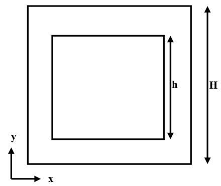
The geometry and computational lines are summarized in Figure 1. The distance H of cavity is fixed to 10 cm and h is 6 cm for source in this study. In the case of an aspect ratio (h/H=0.6). The walls of cavity are maintained at ambient temperature Ta=293 k and for walls source is heated at Tc=313 k.
The moving north wall of cavity is displaced at the velocity V for four cases (V=0m/s ‘fixed wall’, V=1m/s, V=5m/s and V=10m/s).
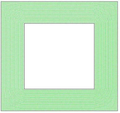
A 2-D structural uniform grid has been generated with 6400 quadrilateral cells Figure 2.
The numerical simulation was carried out under the environment of the CFD code calculation. The algorithm used is SIMPLEC to solve the coupling between velocity and pressure.
Figure 1. Computational geometry
Figure 2. Grid arrangement
The comparison of the average velocity field measured by PIV [1] with the velocity field obtained numerically also shows that the case of vertical wall sat cold temperature is the closest to the real case (Figure 3).
Figure 3. Velocity field in x direction at y=0.09 m
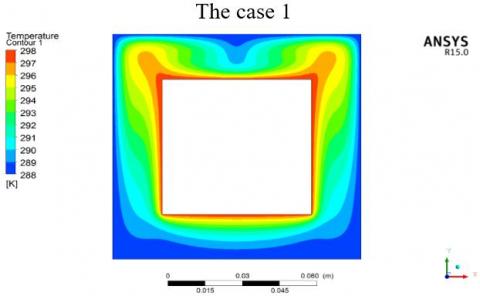
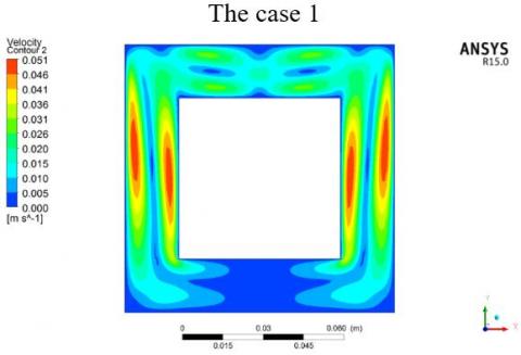
The case 1: The north wall of cavity is fixed velocity V=0 m/s: It can be seen in this numerical study that the flow is laminar, stationary and symmetrical and in addition it is composed of two lateral cells and two secondary cells above the cavity, as confirmed by the experimental work of Ménard [11] (Figures 4, 5).
The case 3: In Figures 8, 9, the north wall has velocity V=5m/s: The increase in speed to 5 m/s of the north wall of the cavity influences the morphology of the flow by creating more recirculation, thus the temperature distribution becomes non-homogeneous in this cavity.
Figure 4. Temperature contour
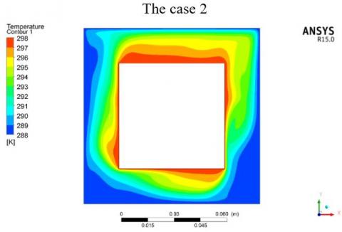
The case 2: The north wall has velocity V=1 m/s: A speed of 1 m/s from the north wall of the cavity leads to the flow towards the east wall of this cavity, which leads to a modification of the location of the temperature and generates non-symmetry in Figures 6, 7.
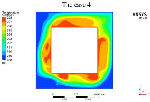
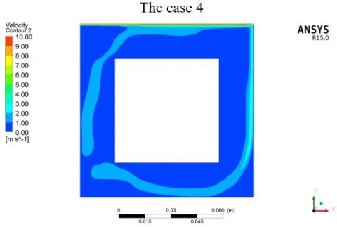
The case 4: The north wall has velocity V=10 m/s: The last case which is the speed 10 m/s of the north wall of the cavity increases the flow speed is the convection becomes forced. This will intensify the heat transfer without creating a homogenization of the temperature (Figures 10, 11).
We can retain that the movement of the upper wall of the cavity makes the natural convection a forced convection and that the heat transfer is more localized on the right. An increase in the speed of this mobile wall generates an increase in temperature homogenization.
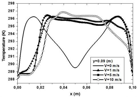
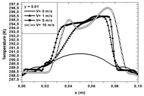
The evolution of the temperature horizontally (y=0.01 m and y=0.09 m) it is symmetrical for a fixed wall and anti-symmetrical for a mobile wall in Figures 12 and 13.
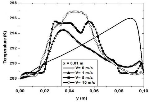
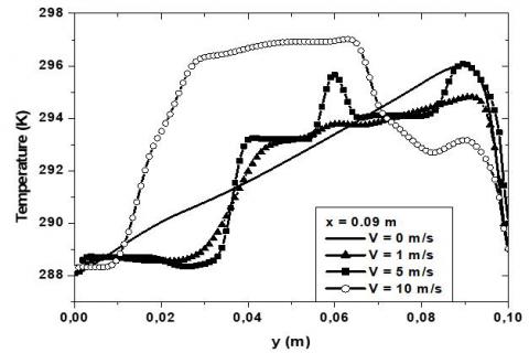
The evolution of the temperature vertically (x=0.01 m and x=0.09 m) is a straight line which increases from the left for a fixed wall whereas this evolution of temperature is more complex for a mobile wall because of the forced convection in Figures 14, 15.
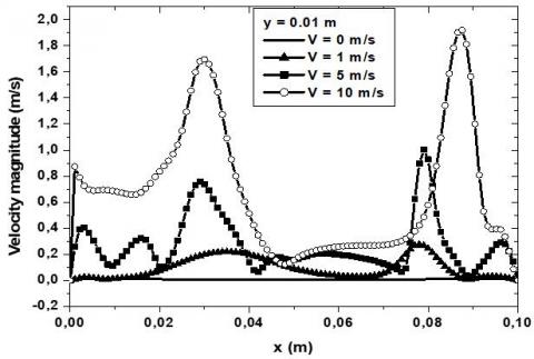
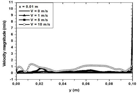
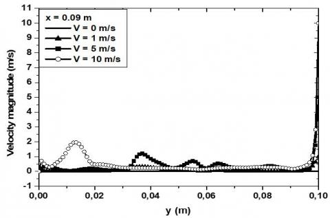
In the case of a fixed wall, the flow velocity is almost zero (free convection), the mobility of the wall increases the flow velocity which will cause the temperature to move (forced making) (Figures 18, 19). An increase in wall velocity causes an increase in flow velocity (Figures 16, 17).
In the case of a fixed wall, the flow is symmetrical and the convection is free.
In the case of a mobile wall, the flow is antisymmetric and the convection is forced.
In the case of a mobile wall with a speed of V=5 m/s, the flow is more disturbed by the presence of several recirculations which are even numerous compared to the mobile wall with a speed of V=10 m/s.
Figure 5. Velocity contour
Figure 6. Temperature contour
Figure 7. Velocity contour
Figure 8. Temperature contour
Figure 9. Velocity contour
Figure 10. Temperature contour
Figure 11. Velocity contour
Figure 12. Temperature profiles comparison at y=0.09 m
Figure 13. Temperature profiles comparison at y=0.01 m
Figure 14. Temperature profiles comparison at x=0.01 m
Figure 15. Temperature profiles comparison at x=0.09 m
Figure 16. Velocity magnitude profiles comparison at y=0.01 m
Figure 17. Velocity magnitude profiles comparison at y=0.09 m
Figure 18. Velocity magnitude profiles comparison at x=0.01 m
Figure 19. Velocity magnitude profiles comparison at x=0.09 m
4.1 Comparison of measurements and calculations of the aspect ratio h/H=0.6 in air
The comparison of the average velocity field measured by PIV with the velocity field obtained numerically also shows that the case of vertical wall sat cold temperature The minimum velocity peak at x=0.05 m indicates the cold fluid descending at the interface of the two upper cells.
Near the walls, the negative velocity peaks come from the descending part of the lateral recirculation cells. From these the figure presents a comparison of the experimental and numerical results (vertical walls) for the vertical component of the velocity above the source (y=90 mm). The two speed peaks correspond to the interface of an upper cell and a side cell.
Two peaks, the vertical speed varies linearly until it becomes zero at the wall. In the boundary layer at the East vertical wall as well as in the rest of the profile, the calculations agree with the PIV and LDV measurements is the closest to the real case. But only the case with cold vertical walls makes it possible to find lateral cells whose minimum and maximum values of the vertical component of the velocity remain greater in absolute value than 2.10-2 m/s over the entire height of the source.
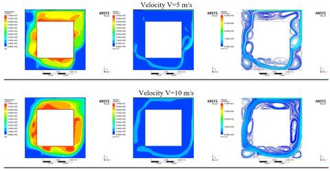
The Figure 20 presents the contours and streamlines of the speeds and temperature for different speeds of the moving upper wall for different cases.
For the case 1, the north wall of the cavity is at a fixed speed V= 0 m/s: It is observed that the flow is laminar, stationary and symmetrical and composed of two lateral cells and two secondary cells above the cavity.
For case 2 where the north wall has a speed V=1 m/s we observe a morphology of the flow by creating the displacement of the fluid with less recirculation, thus the temperature distribution becomes non-homogeneous in this cavity.
For case 3, the north wall has a speed V=5 m/s we notice that the movement of the wall generates more recirculation can be observed clear in the streamline’s configuration, so the temperature distribution becomes non-homogeneous in this cavity.
For case 4, the north wall has a velocity V=10 m/s the north wall of the cavity increases the flow velocity and the convection becomes forced. This will intensify heat transfer without creating temperature homogenization. It can be noted that the movement of the upper wall of the cavity can generate natural convection (fixed wall) and forced convection by an increase in the speed of the upper mobile wall.
Figure 20. Comparison for the four cases (Temperature, Velocity and stream-line)
This parametric study made it possible to explore the influence of different characteristic lengths. Thus, the values of the lower, lateral and upper confinement have a low impact on the heat transfer to the walls.
Conversely, the width and height of the source have a more significant influence. Increasing the width of the source allows the formation of two secondary cells located between the source and the ceiling. This change in topology increases the efficiency of heat transfer to the ceiling. Indeed, while in the reference case, the impact of the plume generates a heat transfer peak on the ceiling, the presence of four counter-rotating cells gives rise to two heat transfer peaks. The influence of the height of the source is even greater. Increasing the height of the source amounts to increasing the motor term of the two recirculation cells. From a height h=0.6 H, the acceleration of the flow allows the development of two secondary cells above the source.
These “crush” the side cells which can no longer reach the ceiling. This modification of the flow modifies the distribution of the heat transfer.
[1] Perrin, L., Reulet, P., Micheli, F., Millan, P., Menard, V. (2005). Dynamical and thermal behaviour of a confined natural convection flow. ONERA: Tire a Part, (203): 1.
[2] Barman, P., Rao, P.S. (2021). Effect of aspect ratio on natural convection in a wavy porous cavity submitted to a partial heat source. International Communications in Heat and Mass Transfer, 126: 105453. https://doi.org/10.1016/j.icheatmasstransfer.2021.105453
[3] Rao, P.S., Barman, P. (2021). Natural convection in a wavy porous cavity subjected to a partial heat source. International Communications in Heat and Mass Transfer, 120: 105007. https://doi.org/10.1016/j.icheatmasstransfer.2020.105007
[4] Feng, Y.Y., Wang, C.H., Xiang, Y., Zhang, X.X. (2022). Internal thermal source effects on convection heat transfer in a two-dimensional porous medium: A lattice Boltzmann study. International Journal of Thermal Sciences, 173: 107416. https://doi.org/10.1016/j.ijthermalsci.2021.107416
[5] Zhang, X., Wang, L., Li, D. (2021). Lattice Boltzmann simulation of natural convection melting in a cubic cavity with an internal cylindrical heat source. International Journal of Thermal Sciences, 165: 106917. https://doi.org/10.1016/j.ijthermalsci.2021.106917
[6] Gibanov, N.S., Sheremet, M.A. (2018). Natural convection in a cubical cavity with different heat source configurations. Thermal Science and Engineering Progress, 7: 138-145. https://doi.org/10.1016/j.tsep.2018.06.004
[7] Fontana, É., Capeletto, C.A., da Silva, A., Mariani, V.C. (2013). Three-dimensional analysis of natural convection in a partially-open cavity with internal heat source. International Journal of Heat and Mass Transfer, 61: 525-542. https://doi.org/10.1016/j.ijheatmasstransfer.2013.02.047
[8] Zhan, N.Y., Xu, Y., Wang, Z.Y. (2015). Research on heat transfer and three-dimensional characteristics of natural convection in a small cavity with heat sources. International Journal of Heat and Technology, 33(3): 59-66. http://dx.doi.org/10.18280/ijht.330308
[9] Kuznetsov, G.V., Sheremet, M.A. (2011). Conjugate natural convection in an enclosure with a heat source of constant heat transfer rate. International Journal of Heat and Mass Transfer, 54(1-3): 260-268. https://doi.org/10.1016/j.ijheatmasstransfer.2010.09.046
[10] Deng, Q.H. (2008). Fluid flow and heat transfer characteristics of natural convection in square cavities due to discrete source–sink pairs. International Journal of Heat and Mass Transfer, 51(25-26): 5949-5957. https://doi.org/10.1016/j.ijheatmasstransfer.2008.04.062
[11] Ménard, V. (2005). Natural convection in a cavity containing a heat source. Thesis, (DMAE) ONERA, Toulouse. No: 446.
[12] Tou, S.K.W., Tso, C.P., Zhang, X. (1999). 3-D numerical analysis of natural convective liquid cooling of a 3×3 heater array in rectangular enclosures. International Journal of Heat and Mass Transfer, 42(17): 3231-3244. https://doi.org/10.1016/S0017-9310(98)00379-2
[13] Abdel-Nour, Z., Aissa, A., Mebarek-Oudina, F., Rashad, A.M., Ali, H.M., Sahnoun, M., El Ganaoui, M. (2020). Magnetohydrodynamic natural convection of hybrid nanofluid in a porous enclosure: numerical analysis of the entropy generation. Journal of Thermal Analysis and Calorimetry, 141(5): 1981-1992. https://doi.org/10.1007/s10973-020-09690-z
[14] Varol, Y., Oztop, H.F., Koca, A., Ozgen, F. (2009). Natural convection and fluid flow in inclined enclosure with a corner heater. Applied Thermal Engineering, 29(2-3): 340-350. https://doi.org/10.1016/j.applthermaleng.2008.02.033
[15] Talesh Bahrami, H.R., Safikhani, H. (2020). Heat transfer enhancement inside an eccentric cylinder with an inner rotating wall using porous media: A numerical study. Journal of Thermal Analysis and Calorimetry, 141(5): 1905-1917. https://doi.org/10.1007/s10973-020-09532-y