Yunfeng Ma* | Linsheng Xu | Ximei Shi
© 2022 IIETA. This article is published by IIETA and is licensed under the CC BY 4.0 license (http://creativecommons.org/licenses/by/4.0/).
OPEN ACCESS
To explore the effect of frost heaving of the tunnel entrance in cold regions, this paper carries out a thermomechanical coupling analysis based on peridynamics (PD), combines PD with finite-element method (FEM) into a numerical model, and verifies the feasibility of the proposed model. On this basis, we selected frost heave amount as the quantitative index, discussed the evolution law of the energy field in the lining structure of the tunnel entrance in cold regions, and analyzed the stress of the lining structure, as well as the expansion and distribution laws of lining cracks, under different frost heave amounts. The results show that: The difference of frost heave amount indirectly brings changes to the system’s energy field. With the growth of frost heave amount, the thermal potential and strain would increase. During the changes, the thermal potential and strain energy of the system are both positively correlated with frost heave amount. The degradability of tunnel lining increases with the frost heave amount of the lining. A high density of cracks can be observed at the foot and waist of the arch, most of which are tensile cracks. With frost heave amount as the main temperature reference, this research explores the degradation state of the tunnel entrance in cold regions, which greatly facilitates the maintenance, repair, and safe operation of tunnels.
lining structure, frost heave amount, energy field, crack expansion
In the cold regions, tunnel construction breaks the dynamic thermal balance of the surrounding rocks. Notably, the cold airflow enters the lining and surrounding rocks at the tunnel entrance, and exchanges heat with these objects. The pore water would freeze into ice, when the temperature drops below 0℃ [1-3]. As the liquid phase turns into solid phase, the volume expansion causes the tunnel lining and the surrounding brocks to generate a frost heave force. When the temperature rises, the ice melts into water, which increases the amount of water in the pores. The displacement of tunnel lining and the surrounding rocks, which occurs during the freezing phase, cannot be fully recovered, resulting in the expansion of the pores. The cyclic freezing and thawing lead to deformation of the lining structure at the tunnel entrance. If the freezing and thawing continue, the tunnel entrance will crack and fail, posing a serious threat to the safe operation of the tunnel [4-7].
Many scholars probed deep into the degradation of tunnel lining in cold regions. To reveal the influence of the phase change from ice to water over the dynamic temperature field of tunnels in cold regions, Xu et al., Min et al., Zhan et al., Keawsawasvong and Ukritchon [8-11] constructed a finite-element model of the target tunnel, and comparatively discussed the dynamic changes of tunnel temperature field with and without the phase change. Xu et al. and Cai et al. [12, 13] revealed the frost heave mechanism of local excess water in tunnels of cold regions, proposed an effective evaluation method for lining structure safety, and designed a three-dimensional (3D) geo-mechanical model test. Frost heave tests were carried out with three different ranges of excess water, and the crack propagation and lining forces were observed during the frost heave process. Qiu et al. [14] evaluated the main analysis models for frost heave pressure in China, and enumerated the deformation constraints of frost heave water bodies, based on the model of water storage space. On this basis, a constrained frost heave model was developed, treating the frost heave pressure as a gas pressure, and the relevant theoretical formulas were provided. Finally, they calculated and analyzed the distribution laws of the active site of frost heave pressure, scale of frost heave water body, and stiffness of tunnel lining and surrounding rocks, as well as how much these factors affect the safety of tunnel lining.
Yau et al. [15] attempted to clarify the effects of the local empty water storage space between tunnel lining and the surrounding rocks on the degradability of tunnel lining. Drawing on the coupling theory between water, heat, and force of the water storage space, the Abaqus software was adopted to theoretically model the water-heat-force coupling, and the tunnel roof settlement and crack distribution were numerically simulated. Through field measurement, indoor test, and COMSOL simulation, Do et al. [16] explored how the magnitude and distribution law of frost heave force are affected by porosity, permeability, random crack diameter, and lower boundary waterhead of the model, under the condition of random cracking. Li et al. [17] noticed that the tunnels in cold regions are prone to cold damages like broken lining and leak water freezing. To prevent such damages, it is necessary to deploy an active heating system, in addition to an insulation layer. The active heating system mainly consists of the ribbon heater between the secondary lining and the insulation layer. Under the negative temperature, concrete specimens were tested by the electric heating model to simulate the temperature rise from the negative level to the positive level, after the concrete of tunnel lining leaks and freezes. The specimens were tested one by one or in groups of three specimens.
Focusing on the degradation state of the lining structure at the entrance of operating tunnels in cold regions, this paper selects the Bapanshan Tunnel between Jiangluo Town to Tianshui City on National Highway 316 as the target, combines peridynamics (PD) with traditional finite-element method (FEM) to build a hybrid model, and relies on the model to analyze the progressive cracking of the lining structure at the tunnel entrance. The FEM and PD domains of the computational model were coupled, based on the strain energy density equivalence principle. After verifying the feasibility of the model, the lining at the tunnel entrance was subjected to thermomechanical coupling analysis.
2.1 Bond type PD thermomechanical coupling theory
In PD, the thermal density between two mass points x and x’ is the temperature difference between them. Based on the diffusion of the heat flow, the bond type PD heat conduction can be expressed as [18]:
$\rho c_{V} \dot{\Theta}(x, t)=\int_{H} f_{\mathrm{h}}\left(\Theta^{\prime}, \Theta, x^{\prime}, x, t\right) \mathrm{d} V_{x^{\prime}}+\rho s_{\mathrm{b}}(x, t)$ (1)
where, fh is the density function of the heat flow, which is only controlled by the interaction between mass points x and x’; $\rho$ is density; cV is the specific heat capacity; sb is the amount of heat generated per unit mass of heat source per unit time; $\Theta$ is the reference temperature at the stress of zero; $\dot{\Theta}$ is the absolute temperature.
In the bond type PD heat diffusion, the interaction between different mass points is independent of each other. The heat flow between a pair of mass points has nothing to do with the temperature difference between other pairs. The thermal response function of the pairs of mass points outside the neighborhood (i.e., $|\xi|=\left|x^{\prime}-x\right|>\delta$) is zero. The bond type PD heat conduction function can be corrected by the deformed heating and cooling terms. Then, the bond type PD thermomechanical coupling equation can be written as [19]:
$\alpha_{V} \dot{\Theta}(x, t)=\int_{H}\left(f_{\mathrm{h}}-\Theta \frac{c}{2} \alpha \dot{e}\right) \mathrm{d} V^{\prime}+\rho_{\mathrm{b}}(x, t)$ (2)
$\dot{e}=\frac{\eta+\xi}{|\eta+\xi|} \cdot \dot{\eta}$ (3)
where, $\dot{e}$ is the time derivative of the elongation between mass points; $\dot{\eta}$ is the time derivative of the relative displacement vector; c is the material parameter of PD; $\eta$ is the relative displacement of a pair of mass points; α is the thermal expansion coefficient; αV is the linear expansion coefficient of temperature between mass points; rb is the thermal density; $\xi$ is the relative position between mass points.
2.2 Initial conditions
To solve the time integral, the initial conditions should be configured. In the target area, the temperature of each mass point can be initialized as [20]:
$\Theta(x, t=0)=\Theta^{*}(x)$ (4)
Temperature can be added as a boundary condition in PD thermal conduction analysis. Let R denote the lining area of the target tunnel. Then, the boundary condition of temperature needs to be applied in a virtual area Rt attached to the outside of the real material St. The numerical test should accurately reflect the specified boundary temperature in the lining area of the tunnel. To this end, the virtual boundary depth must be equal to the neighborhood size δ. Then, the temperature boundary condition can be expressed as [21]:
$\Theta(y, t+\Delta t)=2 \Theta^{*}\left(x^{*}, t+\Delta t\right)-\Theta(z, t) x^{*} \in S_{1}, y \in R_{1}, z \in R$ (5)
where, z is the position of a mass point in R; x* is the position of a point on surface St. The relative position between them can be derived from their shortest distance: $d=\left|x^{*}-z\right|$. The position y of a mass point in Rt is the mirror image of the position of mass point z. The position can be determined according to the positions of points z and $x^{*}: y=z+2 d n$, where the unit vector $n=\left(x^{*}-z\right) /\left|x^{*}-z\right|$.
3.1 Model discretization
To numerically solve the thermomechanical coupling of PD, the solution space must be discretized into multiple sub-domains with constant temperatures. Since the temperature of each sub-domain remains constant, the sub-domains can be viewed as independent integration points. Each point lies at the centroid of the corresponding sub-domain, and has a certain volume and integral weight w(j)=1. The integral term in the governing Eq. (1) can be numerically integrated by [22]:
$\rho(i) c_{v(i)} \dot{\Theta}_{(i)}^{\prime}=\sum_{j=1}^{N} f_{\mathrm{h}}\left\{\tau^{n}\left[x_{(j)}-x_{(i)}\right]\right\} V_{(j)}+h_{s(i)}^{n}$ (6)
where, n is the current time step; i is a mass point; j is a mass point in the neighborhood of mass point $i$; V(j) is the volume of the sub-domain associated with centroid x(j). The time integral can be solved in the format of forward difference.
3.2 Constitutive relationship and damage criterion
The modified physical mechanism-based (PMB) model was taken as the constitutive model. Each pair of mass points is viewed as being connected by a rigid rod element (bond). If $\|\xi\| \leq \delta$, the constitutive force f of the interaction between a pair of mass points can be expressed in the 3D form [23]:
$f(\eta ,\xi )=\frac{\xi +\eta }{\|\xi +\eta \|}\frac{72E}{\pi {{\delta }^{4}}}\left( {{\left( 1-\frac{\|\xi \|}{\delta } \right)}^{2}} \right)s\mu (t,\xi )$ (7)
if $\|\xi\|>\delta$, f=0.
where, ζ is the relative position between a pair of mass points; δ is the near-field range; $\eta$ is the relative displacement of the pair of mass points; s is the relative elongation of the pair of mass points.
In the PD theory, scalar functions $\mu$ and $\varphi(x, t)$ are introduced to illustrate the breaking damage [24]:
$\mu (\xi ,t)=\left\{ \begin{matrix} 1,s\left( {{t}^{\prime }},\xi \right)<{{s}_{0}},0\le {{t}^{\prime }}\le t \\ 0,\text{ Otherwise } \\ \end{matrix} \right.$ (8)
where, s0 is the critical elongation of the pair of mass points. If $\mu$=0, the interaction between the pair of mass points disappears, and the micro bond breakage manifests as cracking on the macro scale. When the damage of the mass points accumulates into a surface, a macrocrack will form. The crack degree $\varphi(x, t)$ at a point in the near-field range can be expressed as [25]:
$\varphi (x,t)=1-\frac{\int_{H}{\mu }(x,t,\xi )d{{V}_{\xi }}}{\int_{H}{d}{{V}_{\xi }}}\left( \begin{matrix} 0 & \text{ Intact } \\ \in (0,1) & \text{ Damaged } \\ 1 & \text{ Broken } \\ \end{matrix} \right.$ (9)
3.3 Numerical simulation
Based on the software extension model of Abaqus, this paper establishes a hybrid model coupling PD with FEM. The simulation background is the main tunnel of the Bapanshan Tunnel between Jiangluo Town to Tianshui City on National Highway 316. The tunnel adopts a composite lining of the thickness of 60cm. The inner contour of the tunnel is a curved wall type three centered arch (height: 7.0m; net width: 10.5m) with the same cross-sectional area. The 30m long entrance of the tunnel was selected for calculation.
According to the long-term monitoring data and the data from the repair and maintenance project of the tunnel in 2018, the tunnel lining has 23 circumferential cracks. Among them, 4 circumferential cracks penetrate the lining. The circumferential cracks are between 0.1 and 5.0mm in width, and 0.0-13.0m in length (except the penetrating cracks). Most circumferential cracks suffer from water seepage and salt-petering.
There are 10 longitudinal cracks in the lining, including 4 on the side walls (width: 0.2-0.3mm), and 6 on the waist and springing line (width: 0.2-0.5mm). There are also 15 diagonal cracks in the lining (width: 0.2-0.6mm; length: 5.0-16.0m). Most diagonal cracks suffer from water seepage and salt-petering. Finally, there are two cross cracks (width: 0.2-0.5mm), mainly on the arch top and side walls. All cross cracks suffer from water seepage and salt-petering.
Without considering burial depth and partial pressure, our numerical simulation mainly focuses on three failure modes: the crushing caused by the concrete reaching the ultimate compressive strain; the tensile cracking caused by the concrete reaching the ultimate tensile strain; the failure of lining bearing capacity induced by crack extension. The maximum main stress criterion was adopted to simulate the lining crack expansion. Tables 1 and 2 list the thermophysical parameters and physio-mechanical parameters of the numerical model of the lining, respectively.
To quantify the degradability of the lining at the tunnel entrance in cold regions, the frost heave amount was selected [26, 27]:
h=f Zd (10)
where, h is frost heave amount; f is the mean frost heave intensity of arch top; Zd is the distance from the frozen surface to the outer surface of the lining.
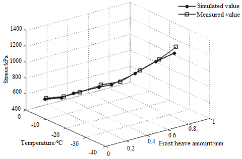
To verify the laws and applicability of lining degradability of the lining at the tunnel entrance obtained through our numerical model under thermomechanical coupling, we compared the simulated temperature stress on the roof with the measured value (Figures 1 and 2).
As shown in Figure 1, when the lining at tunnel entrance is intact, the frost heave amount increased proportionally with the temperature stress, with the variation in temperature. Under the effect of low-temperature frost have, the overall arch top stress slightly increased with the decline of temperature. This phenomenon arises from the following reasons: The tunnel, which was completed in 2006, has been in service for 16 years. During the operation, the tunnel was hit by earthquakes. The rocks of the tunnel are severely softened by the seismic action, as well as the fissure development caused by the abundance of groundwater. As a result, the lining continues to crack, leading to the slight growth in the stress on the arch top.
Figure 1. Simulated and measured values under intact state
|
Mass heat capacity of concrete λ J/(kg·K) |
Heat conductivity of concrete c (W/m·K) |
Linear expansion coefficient of concrete α (m2·h-1) |
Convection coefficient β [kJ/(m2·h·℃-1)] |
Radiation coefficient ε |
Latent heat of phase change of water L kJ/kg |
|
970 |
1.25 |
0.004 08 |
v=3m/s, 67.4 |
0.92 |
590 |
Table 2. Physio-mechanical parameters
|
Elastic modulus E (GPa) |
Bulk density γ (kN/m3) |
Poisson’s ratio ν |
Ultimate tensile stress fc (MPa) |
Maximum circumferential tension σmax (MPa) |
Breaking energy Gf (N/m) |
|
28 |
25 |
0.2 |
22.5 |
2 |
70 |
Figure 2. Simulated and measured values under cracking state
As shown in Figure 2, the simulated distribution and positions of cracks were basically the same as the measured results. In addition, the simulated crack features were consistent with the measured features: the cracks on the inner surface are tensile cracks, while those on the outer surface are shear cracks. Therefore, our model is feasible for simulating the degradability of tunnel lining in cold regions.
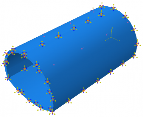
Figure 3. Boundary conditions
Figure 4. Grids
To facilitate model convergence, the surrounding rock pressure was applied uniformly as an additional load on the outer edge of the lining. During the numerical simulation, it is assumed that the lining cracks are filled up with water. We also calculated how much the secondary lining degradability is affected by the additional stress of frost heave produced by pore water, and by the cyclic freezing and thaws. According to PD and the strain energy density equivalence principle of continua, the strain energy density equivalence principle was adopted as the criterion for crack expansion. The damage evolution was simulated by the exponential law based on energy, linear softening, and hybrid mode. The computational domain was meshed into eight-node thermal coupling hexahedrons with linear displacement and linear temperature in three directions. The boundary conditions and grids of the model are shown in Figures 3 and 4, respectively.
4.1 Energy field analysis
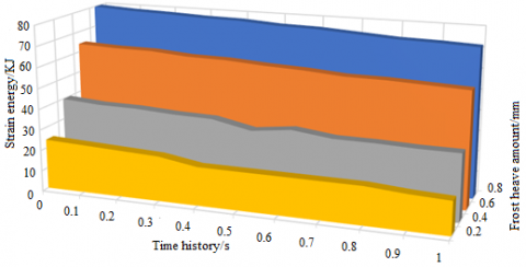
According to the monitoring data on the arch top of the target tunnel, the frost heave amount peaked at about 0.67mm at the roof temperature of -32℃. This study analyzed the evolution law of the energy field in the lining of the tunnel entrance at four different frost heave amounts (0.2mm, 0.4mm, 0.6mm, and 0.8mm). The PD-FEM hybrid model can detect the energy change in the system through energy monitoring. In the initial state, the energy is stored as strain energy in the system. With the application of linear temperature, the energy would be released as thermal potential energy. Figures 5 and 6 show the evolution of thermal potential energy and strain energy at different frost heave amounts, respectively.
When linear temperature is applied to the tunnel entrance, the internal stress state of the tunnel changes because of frost heave, leading to a variation of the thermal potential energy inside the model. The thermal potential energy increases more obviously, with the growth of frost heave amount. As the frost heave amount rose from 0.2 to 0.8, the thermal potential energy increased by 3.6 times. The application of linear temperature reduces the connection between mass points, and slowly suppresses the thermal potential energy of the model. When the frost heave amount remains constant, the thermal potential energy attenuated to 71-81% of the original level. Finally, the model gradually tended to be state. Throughout the application of linear temperature, the thermal potential energy of the model is positively correlated with the strain energy.
Figure 5. Evolution of thermal potential energy
Figure 6. Evolution of strain energy
4.2 Degradability analysis
Figures 7(a)-(d) show the stress change and crack propagation of the lining structure at four different frost heave amounts, after the temperature load was applied to the tunnel section. Under the thermomechanical coupling, the inner stress of the lining structure increased by different degrees, along with crack extension. When the frost heave amount was 0.2mm, no obvious cracking was observed, but the inner surface of the lining had an area of compression concentration. When the frost heave amount reached 0.4mm, the inner surface of the lining started to crack, and the outer surface had an obvious area of compression concentration. When the frost heave amount increased to 0.6mm, a main crack emerged on the inner surface of the lining, and propagated very quickly, while the outer surface was slightly crushed. When the frost heave amount further grew to 0.8mm, the crack distribution on the lining changed. Many cracks expanded to the inner and outer surfaces of the arch waist, and a slight crushing occurred on the arch top. The lining structure failed due to the continuous expansion of cracks on the inner surface of the arch top. Frost heave amount exerted an apparent influence over the lining stress. In the same freezing and thawing cycle, the lining stress increased with frost heave amount. During the gradual expansion of cracks, the inner surface of the lining was mainly subjected to the tensile stress, and damaged by tensile cracks. The growth rates of stress and cracks are both proportional to the frost heave amount.
Under the four frost heave amounts, the cracks were concentrated near the foot and waist of the arch. The corresponding positions on the inner surface of the lining exhibited an obvious tensile feature. In addition, compressive cracks emerged in different degrees at the top, waist, and foot of the arch. During the frost heave of the pore water, many cracks appeared on the inner surface. The cracking process could be summarized as three stages: emergence, coalescence, and re-emergence. This means the shear force and tensile force act alternatively on the lining. The alternative load, which leads to obvious shear damage surfaces, as well as multiple tensile damage lines, significantly accelerates the degradation of the lining. The frost heave at the arch waist is the result of partial pressure. At this position, the inner surface cracks were mostly open, and changed into the X shape with the continuous increase of temperature load. At the foot of the arch, the axial force increased faster than the bending momentum. Under the dominance of the axial force, the crack propagation slowed down. On the inverted arch, a vertical crack appeared, and extended slowly on the inner surface of the lining, under the action of frost heave. In addition, an area of compression concentration appeared on the outer surface of the lining. Judging by the growth rates of stress and cracks, the arch top has the greatest impact on the degradability of the lining.
|
(a) Degradation state at the frost heave amount of 0.2 |
(b) Degradation state at the frost heave amount of 0.4 |
|
(c) Degradation state at the frost heave amount of 0.6 |
(d) Degradation state at the frost heave amount of 0.8 |
Figure 7. Stress change and crack propagation of the lining structure at four different frost heave amounts
(1) Comparison between simulated and measured data shows the PD-FEM hybrid approach is suitable for quantifying the state of tunnels in cold regions under thermomechanical coupling.
(2) After the application of linear temperature, the difference of frost heave amount indirectly drives the change of energy field in the system. With the growth of frost have amount, both thermal potential energy and strain increase. During the change, the thermal potential energy and strain in the system are positively correlated with frost heave amount.
(3) The magnitude of frost heave amount has a significant effect on the stress and crack propagation on tunnel lining. The degradability of tunnel lining increases with frost heave amount. A high density of cracks can be observed at the foot and waist of the arch, most of which are tensile cracks.
This work is supported by the Scientific Research Project of Chongqing Municipal Education Commission (Grant No.: KJQN202003801, KJQN202103807, and KJQN202103809), and College-Level Scientific Research Project, Chongqing Water Resources and Electric Engineering College (Grant No.: (K202025, and K201904).
[1] Dang, L.M., Wang, H., Li, Y., Park, Y., Oh, C., Nguyen, T.N., Moon, H. (2022). Automatic tunnel lining crack evaluation and measurement using deep learning. Tunnelling and Underground Space Technology, 124: 104472. https://doi.org/10.1016/j.tust.2022.104472
[2] Wang, J., Wang, T., Yang, M., Qian, B., Zhang, L., Tian, X., Shi, F. (2022). Research on the influence of different heating zone lengths on pressure waves and a newly designed method of pressure wave mitigation in railway tunnels. Tunnelling and Underground Space Technology, 122: 104379. https://doi.org/10.1016/j.tust.2022.104379
[3] Tao, L., Zhou, X., Tian, X., Ye, X., Zeng, Y., Liu, X. (2022). Study on the temperatures of railway tunnel side ditches in high-latitude cold regions based on the effects of wind. Case Studies in Thermal Engineering, 101793. https://doi.org/10.1016/j.csite.2022.101793
[4] Tao, L., Zeng, Y., Li, J., Yang, G., Fang, Y., Li, B. (2022). Study on the maximum temperature and temperature decay in single-side centralized smoke exhaust tunnel fires. International Journal of Thermal Sciences, 172: 107277. https://doi.org/10.1016/j.ijthermalsci.2021.107277
[5] Zhang, T., Nie, L., Zhang, M., Dai, S., Xu, Y., Du, C., Wang, Y. (2021). Study of temperature field distribution in topographic bias tunnel based on monitoring data. Symmetry, 13(8): 1492. https://doi.org/10.3390/sym13081492
[6] Atzl, G. (2021). Fibre-reinforced tunnel linings-Design and construction experience. Geomechanics and Tunnelling, 14(4): 318-318. https://doi.org/10.1002/geot.202170403
[7] Duan, Y., Rong, C., Cheng, H., Cai, H., Long, W. (2021). Freezing temperature field of FSPR under different pipe configurations: A case study in Gongbei Tunnel, China. Advances in Civil Engineering, 2021. https://doi.org/10.1155/2021/9958165
[8] Xu, X., Zhu, G., Zhang, X., Chai, G., Chu, T. (2021). Numerical study on temperature distribution of tunnel structure in fires. Case Studies in Thermal Engineering, 25: 100874. https://doi.org/10.1016/j.csite.2021.100874
[9] Min, B., Zhang, C., Zhu, W., Zhang, X., Li, P. (2021). Influence of cracks at the invert on the mechanical behavior of the tunnel structures. Thin-Walled Structures, 161: 107405. https://doi.org/10.1016/j.tws.2020.107405
[10] Zhan, Y., Lu, Z., Yao, H. (2020). Numerical analysis of thermo-hydro-mechanical coupling of diversion tunnels in a seasonally frozen region. Journal of Cold Regions Engineering, 34(3): 04020018. https://doi.org/10.1061/(ASCE)CR.1943-5495.0000224
[11] Keawsawasvong, S., Ukritchon, B. (2020). Design equation for stability of shallow unlined circular tunnels in Hoek-Brown rock masses. Bulletin of Engineering Geology and the Environment, 79(8): 4167-4190. https://doi.org/10.1007/s10064-020-01798-8
[12] Xu, P., Wu, Y.M., Wang, Z.J., Huang, L. (2020). Distribution laws of freeze-thaw cycles and unsaturated concrete experiments in cold-region tunnels. Cold Regions Science and Technology, 172: 102985. https://doi.org/10.1016/j.coldregions.2019.102985
[13] Cai, S., Ding, H. (2020). Safety analysis of the secondary lining structure of existing tunnel with cracks. In IOP Conference Series: Materials Science and Engineering, 741(1): 012061. https://doi.org/10.1088/1757-899x/741/1/012061
[14] Qiu, W., Li, B., Gong, L., Qi, X., Deng, Z., Huang, G., Hu, H. (2020). Seismic capacity assessment of cracked lining tunnel based on the pseudo-static method. Tunnelling and Underground Space Technology, 97: 103281. https://doi.org/10.1016/j.tust.2020.103281
[15] Yau, K., Paraskevopoulou, C., Konstantis, S. (2020). Spatial variability of karst and effect on tunnel lining and water inflow. A probabilistic approach. Tunnelling and Underground Space Technology, 97: 103248. https://doi.org/10.1016/j.tust.2019.103248
[16] Do, D.P., Tran, N.T., Mai, V.T., Hoxha, D., Vu, M.N. (2020). Time-dependent reliability analysis of deep tunnel in the viscoelastic burger rock with sequential installation of liners. Rock Mechanics and Rock Engineering, 53(3): 1259-1285. https://doi.org/10.1007/s00603-019-01975-6
[17] Li, G., Ma, B., He, S., Ren, X., Liu, Q. (2020). Automatic tunnel crack detection based on u-net and a convolutional neural network with alternately updated clique. Sensors, 20(3): 717. https://doi.org/10.3390/s20030717
[18] Zhao, X., Zhang, H., Lai, H., Yang, X., Wang, X., Zhao, X. (2020). Temperature field characteristics and influencing factors on frost depth of a highway tunnel in a cold region. Cold regions science and technology, 179: 103141. https://doi.org/10.1016/j.coldregions.2020.103141
[19] Kang, F., Li, Y. (2020). Numerical study on airflow temperature field in a high-temperature tunnel with insulation layer. Applied Thermal Engineering, 179: 115654. https://doi.org/10.1016/j.applthermaleng.2020.115654
[20] Hong, Z., Hu, X., Fang, T. (2020). Analytical solution to steady-state temperature field of Freeze-Sealing Pipe Roof applied to Gongbei tunnel considering operation of limiting tubes. Tunnelling and Underground Space Technology, 105: 103571. https://doi.org/10.1016/j.tust.2020.103571
[21] Farsi, A., Bedi, A., Latham, J.P., Bowers, K. (2020). Simulation of fracture propagation in fibre-reinforced concrete using FDEM: an application to tunnel linings. Computational Particle Mechanics, 7(5): 961-974. https://doi.org/10.1007/s40571-019-00305-5
[22] Zhang, N., Zhu, X., Ren, Y. (2019). Analysis and study on crack characteristics of highway tunnel lining. Civil Engineering Journal, 5(5): 1119-1123. http://dx.doi.org/10.28991/cej-2019-03091316
[23] Schubert, P., Moritz, B. (2019). Cross passages for segmental lined tunnels–structural analysis, test results and practical solutions. Geomechanics and Tunnelling, 12(1): 2-3. https://doi.org/10.1002/geot.201970103
[24] Mori, L., Gül, M., Cheng, R., Sharma, V. (2018). An investigation of the ambient temperature field and thermal response of the Calgary Airport Trail Tunnel. Canadian Journal of Civil Engineering, 45(12): 1015-1026. https://doi.org/10.1139/cjce-2017-0039
[25] Csanady, D., Fenyvesi, O., Lubloy, E.E., Megyeri, T. (2018). Effects of tunnel-fire on load bearing capacity of tunnel-lining and surrounding rock mass. Epitoanyag-Journal of Silicate Based and Composite Materials, 70(2): 54-61. https://doi.org/10.14382/epitoanyag-jsbcm.2018.11.
[26] Pleshko, M., Revyakin, A., Malishevskaya, N. (2018). Investigation of the influence of the railroad track on the stress state of the tunnel lining. In MATEC Web of Conferences, 239: 01020. https://doi.org/10.1051/matecconf/201823901020
[27] Nuianzin, O., Kryshtal, M., Nesterenko, A., Kryshtal, D., Samchenko, T. (2018). Investigation of the regularities of temperature regime of fire in cable tunnels depending on its parameters. In MATEC Web of Conferences, 230: 02022. https://doi.org/10.1051/matecconf/201823002022