Yongfang Lu
© 2022 IIETA. This article is published by IIETA and is licensed under the CC BY 4.0 license (http://creativecommons.org/licenses/by/4.0/).
OPEN ACCESS
With the rapid development of electronic science and technology, power electronic devices are increasingly efficient, intelligent, small, and multi-functional. To ensure the thermal reliability of these devices, it is particularly important to make a reasonable heat dissipation design. However, there is insufficient research into the precise measurement of the flow field and temperature field within real high-voltage power electronic devices under the heat dissipation state of liquid cooling. To fill the gap, this paper carries out a heat flow field analysis on the heat dissipation features of high-wattage power cabinets. Out of the multiple power electronic device groups in a typical high-wattage power cabinet, a row of power electronic device units was taken as the objects. Then, several power electronic devices were analyzed numerically to establish a thermal model of the power electronic device group. Next, we designed the dissipation structure of the group, obtained the correlation between the flow field uniformity and temperature distribution of power electronic devices, and analyzed the effects of the ambient temperature of the group, the flow rate of cooling air, and other factors on the temperature features of power electronic devices. The proposed thermal model and dissipation system design strategy were proved feasible through experiments.
heat flow field analysis, high-wattage power cabinets, heat dissipation features
With the rapid development of electronic science and technology, and the growing functional requirements on electrical equipment, power electronic devices are increasingly efficient, intelligent, small, and multi-functional [1-6]. Some power electronic integrated circuits have reached the thermal flux of 100W/cm2. There are even microwave power devices with higher power consumption per unit volume, and volume power density, and high-wattage power electronic power modules [7-13]. However, the functional integrated power electronic devices have a very limited space. If the heat cannot be vented from the closed space, the power electronic devices might fail [14-18]. To ensure the thermal reliability of power electronic devices, it is particularly important to reduce the high temperature and high heat flow and high thermal flux in the limited space, and to make a reasonable heat dissipation design.
The recent boom of science and technology has motivated domestic industrial producers to handle the heat generated in the production of power electronic devices. Zhu and Liu [19] analyzed the heat generating circuits and groups of power electronic devices, discussed the heat dissipation design of these devices, and detailed the common cooling methods and cooling effects of these devices. Hou et al. [20] introduced a two-phase micro-channel thermal management system that uses refrigerant R1234yf with a low global warming potential. The system contains two identical aluminum micro-channel radiators, which are serial connected in the cooling loop. The other components include a gas flow meter, a micro compressor, a condenser, a throttling device, and an auxiliary measurement device. Experimental results show that the thermal management system can disperse a heat flow of 526 526 W/cm2, while keeping the junction temperature below 120°C. Li et al. [21] explained the thermal effect of the piezoelectric micromechanical ultrasound converter, and expected to apply the device to the heat dissipation of power electronic devices. Experimental results show that, the resonance frequency of the converter did not change much under different external thermal flows. According to simulation and test results, the frequency is negatively correlated with the side length of the converter. With the increase of the thermal flux of integrated circuit chips, the traditional rectangular micro-channel has almost reached the limit. It is important to improve the heat dissipation in the limited space by optimizing the structure or enhancing heat transfer. Li et al. [22] adopted the three-dimensional (3D) conjugate value simulation model to analyze the flow and temperature features of the structure of silicon-based rectangular micro-channels. The results show that the micro-channel with a loose-front, tight-end turbulence chamber boasts the optimal flow and heat transfer performance. The performance can be further improved by increasing the Reynolds number. Wu and Ozpineci [23] focused on understanding the thermal impact of using separate power devices, and the limitations of using traditional thermal design methods. According to experience, the basis of thermal system design is selecting radiators with necessary thermal resistances from the manufacturer’s data list. This approximation approach has proven to be an effective way to preliminarily design silicon-based power modules.
The above studies are significant for understanding the flow field, temperature, and heat flow propagation in the space of power electronic devices. However, all these studies were conducted in the closed space model of the devices. In the real space of the devices, the temperature and heat flow propagate under the heat dissipation mode of liquid cooling. Overall, there is insufficient research into the precise measurement of the flow field and temperature field within real high-voltage power electronic devices under the heat dissipation state of liquid cooling. To fill the gap, this paper carries out a heat flow field analysis on the heat dissipation features of high-wattage power cabinets. Section 2 chooses to study a row of power electronic device units from the multiple power electronic device groups in a typical high-wattage power cabinet, numerically analyzes several power electronic devices, and establishes a thermal model of the power electronic device group. Section 3 deigns the dissipation structure of the group, obtains the correlation between the flow field uniformity and temperature distribution of power electronic devices, and analyzes the effects of the ambient temperature of the group, the flow rate of cooling air, and other factors on the temperature features of power electronic devices. Section 4 verifies the feasibility of the proposed thermal model and dissipation system design strategy through experiments.
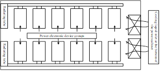
This section chooses to study a row of power electronic device units from the multiple power electronic device groups in a typical high-wattage power cabinet, and numerically analyzes several power electronic devices. Figure 1 shows the internal structure of a typical high-wattage power cabinet.
Figure 1. Internal structure of a typical high-wattage power cabinet
Before building the thermal model of the power electronic device groups in the typical high-wattage power cabinet, the relevant hypotheses need to be established:
(1) Each power electronic device in each group has the same switching features, flow capacity, saturation voltage drop, and driving power.
(2) The thermal behavior of power electronic device groups is equivalent to that of power electronic device groups in other modules.
(3) The heat conduction between power electronic devices via connectors and wires is negligible.
(4) We only considered the Ampere's force power characterized by the current loads of the power cabinet, and the internal resistance of each device group, and ignored the heat loss induced by the Ampere's force power and reversible entropy heat.
Based on the law of energy conservation, this study combines the known heat generation and heat transfer of power electronic device units, and establishes a reduced order thermal model for each power electronic device group, according to the inside, surface, and contact air of power electronic devices. Let Φd,j, Φr,j, and Φx,i be the inner temperature, surface temperature, and contact air temperature of the i-th power electronic device, respectively. The following model can be established:
$D_{d} \frac{d \Phi_{d, i}}{d p}=Z^{2} S+\frac{\Phi_{r, i}-\Phi_{d, i}}{S_{d}}$
$D_{r} \frac{d \Phi_{r, i}}{d p}=\frac{\Phi_{x, i-1}-\Phi_{r, i}}{S_{v}}-\frac{\Phi_{r, i}-\Phi_{d, i}}{S_{d}}$
$D_{g} \frac{d \Phi_{x, i}}{d p}=\frac{\Phi_{r, i-1}-\Phi_{r, i-1}}{S_{v}}+\dot{n}_{x} D_{x}\left(\Phi_{x, i-1}-\Phi_{x, i}\right)$ (1)
According to the proposed reduced order thermal model for each power electronic device group, the state variable of the thermal management system for the power electronic circuit in the high-wattage power cabinet was defined as a=[Φd,i Φr,i Φx,i]T, and the input and output of the system were defined as v=[Z2S Φx,i-1]T and b=Φr,I, respectively. Then, the state of the thermal management system can be given by:
$\dot{a}=\left[\begin{array}{ccc}\frac{-1}{S_{d} D_{d}} & \frac{1}{S_{d} D_{d}} & 0 \\ \frac{1}{S_{d} D_{r}} & \frac{-1}{S_{r} D_{v}}+\frac{-1}{D_{r} S_{d}} & 0 \\ 0 & \frac{1}{S_{v} D_{g}} & \frac{-\dot{n}_{x} d_{x} S_{v}}{D_{g}}\end{array}\right] a+\left[\begin{array}{cc}\frac{1}{D_{d}} & 0 \\ 0 & \frac{1}{S_{v} D_{r}} \\ 0 & \frac{-1+\dot{n}_{x} d_{x} S_{v}}{S_{v} D_{g}}\end{array}\right] v$ (2)
The output of the thermal management system can be expressed as:
$b=\Phi_{r_{, z}}=\left[\begin{array}{lll}0 & 1 & 0\end{array}\right] a$ (3)
After the power electronic circuit has been running for 20 min, the temperature of a power electronic device, and the temperature of the contact air gradually increase along the fluid flow direction. There is a very small temperature difference between adjacent power electronic devices, and the contact airs of the two devices. Considering the small relative error between discrete points and the fitting points of contact air temperature, this paper assumes that the temperature of the cooling liquid from the cooling system gradually increases along its flow direction.
Since it is difficult to measure the mixed air temperature in the flow channel, the temperature of the inlet cooling liquid in the heat dissipation system was selected as the input to the thermal management model. Thus, Φx,i-1 needs to be replaced by Φx,0. Let z be the serial number of power electronic devices. Then, we have the following hypothesis:
$\Phi_{x, 1}=\Phi_{x, 0}+\frac{1}{z}\left(\Phi_{x, z}-\Phi_{x, 0}\right)$
$\Phi_{x, 2}=\Phi_{x, 0}+\frac{2}{z}\left(\Phi_{x, z}-\Phi_{x, 0}\right)$
$\vdots$
$\Phi_{x, z-1}=\Phi_{x, 0}+\frac{z-1}{z}\left(\Phi_{x, z}-\Phi_{x, 0}\right)$ (4)
Combining formulas (4) and (3), it is assumed that a=[Φd,z Φr,z Φx,z]T, v=[Z2S Φx,0]T, the input of the thermal management system is Φx,0, the system disturbance is Z2S, and the system output is Φr,z. The state of the thermal management system of power electronic devices can be expressed as:
$\dot{a}=\left[\begin{array}{ccc}\frac{-1}{S_{d} D_{d}} & \frac{1}{S_{d} D_{d}} & 0 \\ \frac{-1}{S_{d} D_{r}} & \frac{-1}{D_{r} S_{v}}+\frac{-1}{D_{r} S_{d}} & \frac{z-1}{z S_{v} D_{r}} \\ 0 & \frac{1}{S_{v} D_{g}} & \frac{1-z-\dot{n}_{x} d_{x} S_{v}}{z S_{v} D_{g}}\end{array}\right] x+\left[\begin{array}{cc}\frac{1}{D_{d}} & 0 \\ 0 & \frac{1}{z S_{v} D_{r}} \\ 0 & \frac{-1+\dot{n}_{x} d_{x} S_{v}}{z S_{v} D_{g}}\end{array}\right] v$ (5)
The output of the system can be expressed as:
$b=\Phi_{r, z}=\left[\begin{array}{lll}0 & 1 & 0\end{array}\right] a$ (6)
The mainstay of the power cabinet is composed of orderly arranged power electronic device groups. Thus, it is necessary to analyze the cooling effect of the liquid cooling heat dissipation structure of the power cabinet on the power electronic device groups. By exploring the design of the heat dissipation structure, it is possible to obtain the correlation between the uniformity of the corresponding flow field, and the temperature distribution of power electronic devices. Meanwhile, the authors discussed the effects of the ambient temperature of the group, the flow rate of cooling air, and other factors on the temperature features of power electronic devices.
Compared with other cooling liquid heat dissipation structures, the symmetric tree-shaped double bifurcation liquid cooling structure features uniform temperature distribution in the thermal field, and good heat dissipation performance. This structure can reduce the on-state voltage drop of power electronic devices, and further lower their energy consumption.
According to the Murray's law, which distributes fluid by the law of minimum time and energy, if the fluid inside the liquid cooling pie approximates a Newtonian fluid in the laminar state, then the cumulative sum of the third power of the inner diameter for a branch of the liquid cooling pipe equals the cubic value of the inner diameter of the superior pipe. However, this equation does not apply, when the fluid inside the liquid cooling pipe is a turbulence. Then, it is important to optimize the structure of each superior pipe and its branches, in order to derive the relationship between the two values in the case of turbulence. Let k be the friction factor; g be the pipe length; e be the inner diameter of the liquid cooling pipe; τ be the density of the fluid inside the pipe. Then, the inner pressure difference of the pipe can be established based on Darcy’s law:
$\Delta \tau=g \frac{k_{i} \tau u^{2}}{2 e_{i}}$ (7)
The pressure difference of each branch is stated in formula (7). Let wn be the mass flow of the fluid. Then, the flow resistance in the pipe of the turbulence state can be derived from the density, velocity, and profile of the fluid:
$f_{g}=\frac{\Delta t}{w_{n}^{2}}=\frac{8 g k_{i}}{\tau \pi^{2} e_{i}^{5}}$ (8)
Based on formulas (7) and (8), the following equation can be derived:
$f_{g}==\frac{\Delta t}{\left(t w_{u}\right)^{2}}$ (9)
The total volume flow of each branch can be calculated by:
$w_{u}=w_{u 1}+w_{u 1}$ (10)
The branches in the liquid cooling pipe, which is established on the symmetric tree-shaped double bifurcation liquid cooling structure, are parallel connected. Thus, the flow resistance of the two branches can be calculated by:
$f_{g}=\frac{1}{\left(f_{g 1}^{-\frac{1}{2}}+f_{g 2}^{-\frac{1}{2}}\right)^{2}}$ (11)
Each superior pipe can be viewed as the serial connection between its two branches. Thus, the total flow resistance of an entire branch can be calculated by:
$f_{g \text { total }}=f_{g 0}+f_{g}=f_{g 0}+\frac{1}{\left(f_{g 1}^{-\frac{1}{2}}+f_{g 2}^{-\frac{1}{2}}\right)^{2}}$ (12)
Combining formula (12) and formula (8), the total flow resistance of the entire structure can be calculated by:
$f_{g \text {-total }}$=$\frac{8 g}{\tau \pi^{2}}\left[\frac{k_{0}}{e_{0}^{5}}+\frac{1}{\left(e_{1}^{5 / 2} / k_{1}^{1 / 2}+e_{2}^{5 / 2} / k_{2}^{1 / 2}\right)\quad^{2}}\right]$ (13)
Provided that the inner space of the power cabinet remains the same, the liquid cooling system is optimized to minimize the energy consumption of power electronic devices. Then, the volume of a single bifurcation structure can be calculated by:
$U=\frac{\pi}{4}\left(k_{0} / e_{0}^{2}+k_{1} e_{1}^{2}+k_{2} e_{2}^{2}\right)$ (14)
To minimize the flow resistance in the liquid cooling pipe, this paper introduces the Lagrange function G. Let μ be the Lagrange factor. Then, function G can be obtained by combining formulas (13) and (14):
$G=\frac{k_{0}}{e_{0}^{7}} \frac{1}{\left(e_{1}^{5 / 2} / k_{1}^{1 / 2}+e_{2}^{5 / 2} / k_{2}^{1 / 2}\right)^{2}}+\mu\left(k_{0} / e_{0}^{2}+k_{1} e_{1}^{2}+k_{2} e_{2}^{2}-U\right)$ (15)
Finding the derivative of G to dv, dk, and dx, respectively, and making the derivatives zero:
$\begin{aligned} e_{0}^{7} &=\frac{5}{2 \mu} \\ e_{1}^{7} &=\frac{5}{2 \mu} \frac{\left(e_{1}^{5 / 2} / k_{1}^{1 / 2}\right)^{3}}{\left(e_{1}^{5 / 2} / k_{1}^{1 / 2}+e_{2}^{5 / 2} / k_{2}^{1 / 2}\right)^{3}} \\ e_{2}^{7} &=\frac{5}{2 \mu} \frac{\left(e_{2}^{5 / 2} / k_{2}^{1 / 2}\right)^{3}}{\left(e_{1}^{5 / 2} / k_{1}^{1 / 2}+e_{2}^{5 / 2} / k_{2}^{1 / 2}\right)^{3}} \end{aligned}$ (16)
The above results can be derived comprehensively to obtain:
$e_{0}^{\frac{7}{3}}=e_{1}^{\frac{7}{3}}+e_{2}^{\frac{7}{3}}$ (17)
$k_{1} / k_{2}=\left(e_{1} / e_{2}\right)^{\frac{1}{2}}$ (18)
From formula (18), the optimal relationship can be derived between the branch diameter and the diameter of the superior pipe. In addition, it can be obtained that the length ratio of the two branches equals 1/3 order of their diameter ratio. For our symmetric tree-shaped double bifurcation liquid cooling structure, the two branches of each superior pipe must have the same diameter and length, and the diameter of each superior pipe must satisfy e0=23/7e1,2.
Considering the actual space inside the power cabinet, the proposed liquid cooling pipe network has a power series of 5, and 2 bifurcations. Through the calculation principle in this section, the structural dimensions of the network can be obtained, including the diameter and length of the liquid cooling pipe.
(a)Inlet flow
(b)Outlet flow
Figure 2. Inlet and outlet flows of cooling liquid of the heat dissipation system before and after system optimization
Figure 2 compares the inlet and outlet flows of cooling liquid of the heat dissipation system before and after system optimization. It can be seen that the optimization of the thermal management system significantly suppressed the flow fluctuation of the cooling liquid, resulting in a close to optimal heat dissipation state. Of course, the liquid flows in some liquid cooling pipes oscillated slightly, because the location of the heat dissipation system cannot be easily in the power cabinet. For our symmetric tree-shaped double bifurcation liquid cooling structure, the nonuniformity of fluid flow in some pipes is acceptable, facing the constraints of the outer boundaries of power electronic devices. Further structural adjustment would affect the flows in other branches. As shown in Figure 2, the proposed thermal model and the proposed design strategy for the heat dissipation system are both feasible. The distribution of the heat flow field is significantly improved, after the thermal management system is optimized by our strategy.
Figure 3. Inside, surface, and contact air temperatures of each device
Figure 4. Temperatures of different device groups
Figure 3 presents the inside, surface, and contact air temperatures of each device. Figure 4 displays the temperatures of different device groups at different positions. It can be observed that, under the velocity inlet boundary condition, all power electronic devices inside the cabinet had basically the same temperature. Their temperature difference was smaller than the pipe inlet boundary condition. Comparing the two sets of simulation results, it can be learned that, for the cooling liquid velocity in the pipe, the actual working condition of the pipe could not be simulated, if the flow is fixed under the velocity inlet condition. It is better to use the pipe inlet boundary condition.
To further explore the influence of pipe width and liquid mass flow on the heat dissipation of device groups, the highest temperature of power electronic devices was taken as the metric of heat dissipation performance of the power cabinet, and a comparative experiment was carried out. Since only two parameters are considered, it is not necessary to adopt the orthogonal design. Thus, the data were processed through the binary variance analysis of the non-repeatable tests. Table 1 compares the device temperatures at different combinations. Table 2 compares the temperatures and pipe outlet pressures before and after system optimization.
The results in Tables 1 and 2 show that the symmetric tree-shaped double bifurcation liquid cooling structure reduced the pipe outlet pressure, ensured the smooth flow of cooling liquid in each branch, boosted the liquid flow capacity (which is constrained by the limited space of the power cabinet), and lowered the inside temperature of the cabinet in normal operation.
Table 1. Device temperatures at different combinations
|
Inner diameter Mass flow |
350 |
400 |
450 |
|
0.24 |
72.5℃ |
69.7℃ |
65.2℃ |
|
0.25 |
67.9℃ |
63.1℃ |
62.8℃ |
|
0.26 |
61.4℃ |
68.2℃ |
62.7℃ |
|
0.27 |
60.9℃ |
69.2℃ |
65.6℃ |
Table 2. Temperatures and pipe outlet pressures before and after system optimization
|
|
Pre-optimization |
Post-optimization |
Variation |
|
|
Temperature |
Mean |
63.8 |
69.4 |
-2.4 |
|
Maximum |
71.5 |
66.7 |
-2.1 |
|
|
Minimum |
66.3 |
63.9 |
-1.3 |
|
|
Pipe outlet pressure |
Mean |
32.8 |
25.8 |
-6.7 |
|
Maximum |
35.2 |
29.4 |
-5.2 |
|
|
Minimum |
25.9 |
16.2 |
-6.9 |
|
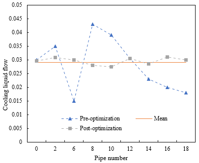
Figure 5. Cooling fluid flows after optimization
Due to the high processing cost, this study only processes the heat dissipation structure after the optimization of the thermal management system. The mass flow of the cooling liquid was controlled at about 0.25 kg/s. Then, the flows in the 18 branches of the liquid cooling pipe were counted and ranked. Figure 5 compares the test value and actual value of each branch flow. It can be observed that the model simplification causes an error between inlet-outlet pressure difference of the liquid cooling pipe in the heat dissipation system. The maximum error was less than 8.7%, and the mean error was 0.89%. The reason is that the actual flow resistance is large for the cooling liquid in the heat dissipation system. The results demonstrate the reliability of our simulation.
Taking high-wattage power cabinets as example, this paper explores the heat dissipation features through heat flow field analysis. Out of the multiple power electronic device groups in a typical high-wattage power cabinet, a row of power electronic device units was taken as the objects. Next, several power electronic devices were analyzed numerically to establish a thermal model of the power electronic device group. After that, the authors devised the dissipation structure of the group, obtained the correlation between the flow field uniformity and temperature distribution of power electronic devices, and analyzed the effects of the ambient temperature of the group, the flow rate of cooling air, and other factors on the temperature features of power electronic devices.
Through experiments, the inlet and outlet flows of cooling liquid of the heat dissipation system before system optimization were compared with those after the optimization, revealing that the optimization of the thermal management system significantly suppressed the flow fluctuation of the cooling liquid, resulting in a close to optimal heat dissipation state. In addition, the temperatures of device groups at different positions were displayed. The results show that, it is better to use the pipe inlet boundary condition. To further explore the influence of pipe width and liquid mass flow on the heat dissipation of device groups, the highest temperature of power electronic devices was taken as the metric of heat dissipation performance of the power cabinet. The cooling liquid flows before and after the optimization were compared, which further verifies the feasibility of the proposed thermal model and design strategy for heat dissipation system.
[1] Yu, L., Sun, H.D., Xu, S.Y., Zhao, B., Zhang, J., Li, Z.H. (2022). Overview of strength quantification indexes of power system with power electronic equipment. Proceedings of the Chinese Society of Electrical Engineering, 42(2): 499-514.
[2] Broadley, E.T. (2014). Autonomous power supplies for remote, safety critical electronic equipment. Road Transport Information and Control Conference 2014 (RTIC 2014). https://doi.org/10.1049/cp.2014.0804
[3] He, X., Zong, S., Wu, J., Zhao, R. (2014). Technologies of power electronic equipment interconnecting and networking in distribution grids. Proc CSEE, 34(29): 5162-5170. https://doi.org/10.13334/j.0258-8013.pcsee.2014.29.018
[4] Duan, Z., Yuan, X., Zhu, R. (2021). Application of fuzzy control harmonic suppression and reactive power compensation technology for power electronic equipment based on cloud computing. Journal of Intelligent & Fuzzy Systems, 40(4): 5795-5806. https://doi.org/10.3233/JIFS-189419
[5] Zhang, Z., Schürhuber, R., Fickert, L., Friedl, K., Chen, G., Zhang, Y. (2021). Systematic stability analysis, evaluation and testing process, and platform for grid-connected power electronic equipment. E&I Elektrotechnik and Informationstechnik, 138(1): 20-30. https://doi.org/10.1007/s00502-020-00857-y
[6] He, D.X., Zhang, T., Chen, X.G., Gong, W.J., Li, Q.Q. (2021). Research overview on charge characteristics of power electronic equipment insulation under the pulse voltage. Transactions of China Electrotechnical Society, 36(22): 4795-4808.
[7] Lee, B.H., Moon, G.W. (2012). Zero no-load power AC/DC adapter for electronic equipment with embedded battery. IEEE transactions on power electronics, 28(7): 3073-3076. https://doi.org/10.1109/TPEL.2012.2222670
[8] Nitzsche, M., Zehelein, M., Troester, N., Roth-Stielow, J. (2018). Precise voltage measurement for power electronics with high switching frequencies. In PCIM Europe 2018; International Exhibition and Conference for Power Electronics, Intelligent Motion, Renewable Energy and Energy Management, 225809: 1356-1361. https://doi.org/10.18419/opus-10745
[9] Fan, P., Huang, S., Wang, H., Luo, D., Li, H., Sun, M. (2018). Fundamental frequency region-based thermal control of power electronics modules in high power motor drive. Microelectronics Reliability, 88: 1242-1246. https://doi.org/10.1016/j.microrel.2018.07.036
[10] Saini, A. (2015). Demands are high for low-power electronics. MRS Bulletin, 40(7): 556-557. https://doi.org/10.1557/mrs.2015.147
[11] Savkin, V.Y., Yakovlev, D.V. (2015). A high-voltage pulse modulator for high-power microwave electronics. Instruments and Experimental Techniques, 58(6): 741-744. https://doi.org/10.1134/S0020441215050139
[12] Won, Y., Cho, J., Agonafer, D., Asheghi, M., Goodson, K.E. (2015). Fundamental cooling limits for high power density gallium nitride electronics. IEEE transactions on components, Packaging and Manufacturing Technology, 5(6): 737-744. https://doi.org/10.1109/TCPMT.2015.2433132
[13] Chen, J.T., Bergsten, J., Lu, J., Janzén, E., Thorsell, M., Hultman, L., Kordina, O. (2018). A GaN–SiC hybrid material for high-frequency and power electronics. Applied Physics Letters, 113(4): 041605. https://doi.org/10.1063/1.5042049
[14] Borakhade, K., Mahalle, A. (2018). Enhanced forced convection heat dissipation in power electronics systems by copper metal foam. In 2018 IEEE 8th Power India International Conference (PIICON), pp. 1-5. https://doi.org/10.1109/POWERI.2018.8704413
[15] Mansouri, N., Weasner, C., Zaghlol, A. (2018). Characterization of a heat sink with embedded heat pipe with variable heat dissipating source placement for power electronics applications. In 2018 17th IEEE Intersociety Conference on Thermal and Thermomechanical Phenomena in Electronic Systems (ITherm), pp. 311-317. https://doi.org/10.1109/ITHERM.2018.8419599
[16] Wang, Z.D. (2021). Thermal design and cooling performance evaluation of electronic equipment containing power electronic devices. International Journal of Heat and Technology, 39(2): 451-459. https://doi.org/10.18280/ijht.390214
[17] Li, H.C., Chen, F.F., Dong, Y.G. (2012). An unsteady-state measurement method for charactering heat dissipation properties of power electronic devices. Transactions of China Electrotechnical Society, 27(2): 114-120.
[18] Christensen, A., Doolittle, W.A., Graham, S. (2005). Heat dissipation in high-power GaN electronics on thermally resistive substrates. IEEE Transactions on Electron Devices, 52(8): 1683-1688. https://doi.org/10.1109/TED.2005.851815
[19] Zhu, L., Liu, C. (2020). Selection of radiators in power electronics and analysis of heat dissipation. In Journal of Physics: Conference Series, 1578(1): 012220.
[20] Hou, F., Zhang, H., Huang, D., Fan, J., Liu, F., Lin, T., Zhang, G. (2020). Microchannel thermal management system with two-phase flow for power electronics over 500 W/cm 2 heat dissipation. IEEE transactions on power electronics, 35(10): 10592-10600. https://doi.org/10.1109/TPEL.2020.2985117
[21] Li, N., Chiu, Y., Gong, D., Ma, S., Sun, Y., Li, T., Jin, Y. (2019). Thermal effect of PMUT and its application to the heat dissipation of power electronics. In 2019 IEEE 14th International Conference on Nano/Micro Engineered and Molecular Systems (NEMS), 540-544. https://doi.org/10.1109/NEMS.2019.8915654
[22] Li, F., Zhu, W., He, H. (2018). Numerical study on a novel microchannel structure towards high efficient heat dissipation in high power electronics. In 2018 19th International Conference on Electronic Packaging Technology (ICEPT), 1145-1148. https://doi.org/10.1109/ICEPT.2018.8480799
[23] Wu, T., Ozpineci, B. (2018). Impact of heat dissipation profiles on power electronics packaging design. In 2018 IEEE Transportation Electrification Conference and Expo (ITEC), 482-487. https://doi.org/10.1109/ITEC.2018.8450200