Min Niu
© 2022 IIETA. This article is published by IIETA and is licensed under the CC BY 4.0 license (http://creativecommons.org/licenses/by/4.0/).
OPEN ACCESS
Objective of this research is to analyze the stress of coated cutting tools under high temperature friction, and figure out the laws in the stress change under different loads and rotate speeds. This paper constructed a finite element model and used it to analyze the frictional wear between the test block (ZrN-coated series hard alloy cutting tools) and the high-speed steel friction ring. In the experiment, with the effect of high temperature taken into consideration, the friction process was dynamically simulated under different loads and rotate speeds, the laws of the distribution of stress during this process under the mentioned conditions were attained, and the results of multiple sets of experiments showed that, the maximum equivalent stress and shear stress of uncoated hard alloy cutting tools were significantly higher than those of coated cutting tools. The maximum principal stress appeared in the center part of the contact area of the friction pair, and the maximum shear stress appeared in left-of-center part of the contact area of the friction pair, its size increased with the rise of load, while the rotate speed had little impact on it. The stress analysis of ZrN-coated cutting tools can provide useful theoretical reference for the fabrication of ZrN-coated cutting tools.
coated cutting tool, high temperature, principal stress, shear stress
The variety of coatings, the diversity of processed materials, the change of cutting amount, and the effect of high temperature friction together bring great difficulties for the tests on the performance of the coatings, which has ultimately hindered and limited the promotion and application of coated cutting tools. Thus, it’s a necessary work to analyze the stress distribution of coated cutting tools under high temperature friction according to the failure mode of the coated cutter, thereby figuring out the main mechanism of using coatings to prolong the service life of coated cutter, improving its cutting performance, and enhancing its wear resistance, and this work is also very meaningful for the extensive development and application of coated cutting tools. The early failure of coatings is mainly caused by the separation, delamination, cracking, and spalling of the coating material; and the properties of the coating and the substrate and the properties of the interface between the two have significant effects on the wear of the coatings.
The basic principle of the coated cutting tools is to coat one or more layers of refractory compounds with good wear resistance on the tool body with good toughness, thereby combining the tool substrate with the hard coatings to improve the performance of the cutter. Coated cutting tools generally have higher machining efficiency and precision, longer service life, and lower processing cost [1-5], therefore, they are developing fast in recent years, the fabrication techniques get more mature, and the proportion of coated cutters in indexable inserts has been on the rise over the years in western countries with developed industry [6-9]. In Sweden company Sandvik and American company Kennametal, the proportion of coated cutting tools has exceeded 85%; in the United States, the proportion of coated hard alloy cutters used on CNC machines reached 80%, while in Sweden and Germany, this value has reached 70%. Coated cutting tools integrate many merits such as high-strength substrate, good toughness, high-hardness coatings, and good wear resistance, it has improved the wear resistance of the cutter without hurting its toughness [10-12].
In western countries, in order to improve the cutting performance and service life of high-speed steel, scholars have conducted in-depth research on the properties of the wear-resistant coatings with carbides and nitrides of Ti and Zr (both in group IV) as the coating materials, and attained some useful results, such as the microhardness value of ZrN coating reached as high as about 400MPa [13], it has excellent adhesion, and the critical load in scratch test reached 80N; moreover, the wear resistance test showed that the service life of TiN-coated and ZrN-coated drill bits was 5 times and 7 times longer than that of ordinary drill bits when used on alloy steel plates. Sue and Chang [14] studied the high temperature wear resistance of ZrN and another coating material and found that the hardness of the coatings was 18.9GPa and 20.8GPa, respectively; the experimental results suggested that, when pairing with Inconel 718, the high temperature wear resistance of the ZrN coating at 500℃ was better than that of the TiN coating, the main wear mechanism of the coatings was adhesion wear, oxidation wear, and chemical wear. Ostrovskaya et al. [15] studied the friction of coatings in liquid nitrogen at 77K, and concluded that the properties of the substrate had a greater impact on the friction of coatings, and the coefficient of friction in liquid nitrogen was lower than that in air. Some other scholars also analyzed the stress state and wear mechanism under high temperature friction [16-22]. In their papers, various coating materials and alloy materials were tested under different temperatures and loads, the morphology characteristics of the worn surface and sub-surface of the materials were analyzed, questions such as the adhesive wear at high temperature were considered, and the wear mechanisms of the coating materials and alloy materials were verified. In addition, the damage of coatings caused by friction and wear was ultimately determined by the spatial stress distribution of the coating substrate system, to figure out the friction and wear mechanisms of the coatings, some scholars performed finite element analysis on the stress distribution of coated cutting tools under high temperature friction and calculated its values [23-25].
Under high temperature friction, the wear of coating materials on the coated cutting tools is aggravated due to the action of stress, ultimately, it is determined by the spatial distribution of the stress in the coating/substrate system. To figure out the friction and wear mechanisms of coating materials, finite element analysis is often adopted to calculate the stress distribution of hard alloy cutting tools coated with ZrN series coating materials under friction and wear. However, classical research on contact mechanics mainly solves the problem of spatial semi-infinite bodies made of homogeneous materials, while the analytical formula for the contact stress of composite coatings under high temperature friction has not been established yet. Other problems pending for solutions include which type of models and reasonable boundary conditions should be adopted and what calculation and analysis methods should be chosen so that the calculation results could not only satisfy the analytical formulas of classical contact mechanics, but also characterize the effect of coating structure and material parameters on the coating/substrate contact stress. Now the friction force has been introduced into the analysis system to analyze the stress state of the coating/substrate system from three dimensions, moreover, to improve the function and performance of the coatings, the coating system is developing towards the multi-layer structure, in such case, how to select suitable software platform and boundary conditions so that the analysis method and process could be applicable to the analysis of multi-layer coating system is another problem to be solved.
This paper employed the nonlinear finite element theory to analyze the contact of objects, the criteria of contact state under high temperature, and the basic finite element equations, in this way, the analytical problem of coated cutting tools under high temperature was simplified; then, the paper analyzed the stress produced by the friction between the test block (ZrN-coated cutter) and the friction ring (hereinafter referred to as “block-ring friction” for short) under high temperature, constructed a finite element model and layered and meshed it, set boundary conditions, and applied different loads and rotate speeds to analyze the stress of the coated cutter during high temperature friction and determine basic theories of the fabrication process of coated cutting tools. Since a too high temperature can cause changes to the properties of the coating and the stress distribution of the coated cutter, this study determined the locations with larger stress on the coated cutter, so that coated cutting tools with better performance could be fabricated in the future.
2.1 Criteria of contact state at high temperature
In finite element analysis, the analysis of block-ring friction under high temperature is a type of nonlinear contact analysis. Where two or more objects are in contact, there’re mutual connections between them, such as the surface displacement and force of the contacting objects are the basic conditions of their contact state. By analyzing the contact conditions between them, the contact state of two or more objects could be determined. The contact state can be divided into three types: continuous boundary, sliding boundary, and free boundary. The general contact conditions for judging the contact state using relative displacement and surface force on the contact surface are given below: since they need to be shown in the local coordinate system of the contact surface, at first, the local coordinate system of the contact surface was established. If two objects A and B are in contact, the local coordinate system on object B is X, Y, Z, where Z is the outer normal of the contact surface, and X and Y represent the contact tangent plane.
Assuming: Uji and Rji respectively represent the displacement component and contact force component of the j-th contacting object (j=A, B) in the i-th direction in the local coordinate system, then the judgement criteria of the three types of contact state are:
(1) Continuous boundary conditions:
$\vec{R}_{A i}=-\vec{R}_{B i}(i=\vec{x}, \vec{y}, \vec{z})$ (1)
$\vec{U}_{A} \vec{z}=\vec{U}_{B} \vec{z}+\vec{\delta}_{O} \vec{z}$ (2)
$\overrightarrow{U_{A i}}=U_{B \vec{i}}(i=\vec{x}, \vec{y})$ (3)
where, $\vec{\delta}_{o \vec{z}}$ represents the initial clearance of the contact surface in direction $\vec{Z}$.
At the same time, it needs to satisfy that the tangential plane won’t slide, namely:
${{\overset{\to }{\mathop{R}}\,}_{B\overset{\to }{\mathop{i}}\,}}\le 0,\text{ }\sqrt{\overset{\to }{\mathop{{{R}_{B\overset{\to }{\mathop{x}}\,}}^{2}}}\,+\overset{\to }{\mathop{{{R}_{B\overset{\to }{\mathop{y}}\,}}^{2}}}\,}\le \mu \left| \overset{\to }{\mathop{{{R}_{B\overset{\to }{\mathop{z}}\,}}}}\, \right|$ (4)
where, $\mu$ represents the coefficient of sliding friction between the two contact surfaces.
(2) Free boundary conditions:
$\overset{\to }{\mathop{{{R}_{Ai}}}}\,=-\overset{\to }{\mathop{{{R}_{Bi}}}}\,(i=\overset{\to }{\mathop{x}}\,\overset{\to }{\mathop{y}}\,\overset{\to }{\mathop{z}}\,)$ (5)
And it satisfies:
${{\overset{\to }{\mathop{U}}\,}_{A\overset{\to }{\mathop{z}}\,}}>{{\overset{\to }{\mathop{U}}\,}_{B\overset{\to }{\mathop{z}}\,}}+\overset{\to }{\mathop{{{\delta }_{O\overset{\to }{\mathop{z}}\,}}}}\,$ (6)
(3) Sliding boundary conditions:
${{\overset{\to }{\mathop{U}}\,}_{A\overset{\to }{\mathop{z}}\,}}={{\overset{\to }{\mathop{U}}\,}_{B\overset{\to }{\mathop{z}}\,}}+\overset{\to }{\mathop{{{\delta }_{O\overset{\to }{\mathop{z}}\,}}}}\,,\text{ }{{\overset{\to }{\mathop{R}}\,}_{Ai}}=-{{\overset{\to }{\mathop{R}}\,}_{Bi}}(i=\overset{\to }{\mathop{x}}\,,\overset{\to }{\mathop{y}}\,,\overset{\to }{\mathop{z}}\,)$ (7)
where,
${{\overset{\to }{\mathop{R}}\,}_{B\overset{\to }{\mathop{x}}\,}}=\mu \left| {{\overset{\to }{\mathop{R}}\,}_{B\overset{\to }{\mathop{z}}\,}} \right|\cos \theta ,\text{ }{{\overset{\to }{\mathop{R}}\,}_{B\overset{\to }{\mathop{xy}}\,}}=\mu \left| {{\overset{\to }{\mathop{R}}\,}_{B\overset{\to }{\mathop{z}}\,}} \right|\sin \theta $ (8)
$\cos \theta=\frac{\vec{R}_{B \vec{x}}}{\sqrt{\vec{R}_{B \vec{x}}^{2}+\vec{R}_{B \vec{y}}^{2}}}, \sin \theta=\frac{\vec{R}_{B \vec{d}}}{\sqrt{\vec{R}_{B \vec{x}}^{2}+\vec{R}_{B \vec{y}}^{2}}}$ (9)
Which can be written as:
$\sqrt{{{\overrightarrow{R}}_{B\overrightarrow{x}}}^{2}+{{\overrightarrow{R}}_{B\overrightarrow{y}}}^{2}}>\mu \left| {{\overrightarrow{R}}_{B\overrightarrow{z}}}^{2} \right|$ (10)
For given contact boundary conditions, when the external load is fixed, the contact boundaries of different segments could be divided into different contact state types according to the above-mentioned judgement criteria, however, one thing must be noticed is that, in the three criteria, the relative displacement and the reaction force of the contacting objects on the contact surface will be used, but they are usually unknown. Therefore, in the solution to the contact problem, the first step is to assume the contact state, give the numerical analysis equation based on the assumed contact state, and then solve the relative displacement and reaction force of the contacting objects on the contact surface. The second step is to judge and correct the original contact state based on the attained results and take high temperature and other factors into consideration. After that, these two steps are repeated in cycles continuously until the final contact state is stabilized, so this is a nonlinear local geometric problem that needs to be solved via iterations.
2.2 Basic finite element equations
For a contact problem containing two objects A and B, the two objects could be separated into two independent objects, then their respective basic finite element equation could be easily written as:
$\left[\mathrm{K}_{\mathrm{a}}\right]\left\{\mu_{\mathrm{a}}\right\}=\left\{\mathrm{R}_{\mathrm{a}}\right\}+\left\{\mathrm{P}_{\mathrm{a}}\right\}$ (11)
$\left[\mathrm{K}_{\mathrm{b}}\right]\left\{\mu_{\mathrm{b}}\right\}=\left\{\mathrm{R}_{\mathrm{b}}\right\}+\left\{\mathrm{P}_{\mathrm{b}}\right\}$ (12)
where, [Ka] represents the stiffness matrix of object A; [Kb] represents the stiffness matrix of object B; $\left\{\mu_{a}\right\}$ represents the node displacement vector of object A; {Ra} represents the node displacement vector of object B; {Ra} represents the contact force vector of object A; {Rb} represents the contact force vector of object B; {Pa} represents the vector of external force acting on object A; {Pb} represents the vector of external force acting on object B.
After solving {Ra} and {Rb} through the displacement compatibility relationship between the contacting point pairs, the equations were converted into classical finite element displacement method, then the problem became easier to solve.
3.1 The finite element model and meshing
Analyzing stress under the action of high temperature is a complex system project. At first, an accurately established finite element model is required, then, the appropriate element type should be selected. To achieve high calculation accuracy, according to the stress state of ZrN-coated cutter on the friction and wear testing machine, three-dimensional solid elements should be adopted for discrete meshing, that is, to discretize the solid model into several quadrilateral patch units and analyze the stress, and then use the equilibrium conditions and continuous conditions to assemble the units into an overall structure.
When building the 3D solid model of test block and friction ring using finite elements, the effect of high temperature and the thermoplastic deformation coefficient of the material should be taken into consideration, while when building the solid model, it’s not necessary to pay attention to the specific geometric features of the finite element model such as nodes and units. The geometric shape of the structure was expressed mathematically, nodes and units were added in the geometric model, and loads were applied on the boundary of the geometric model. In fact, the geometric solid model did not participate in the finite element analysis, but generated the finite element analysis model through meshing. All loads and constraints applied and imposed on the boundary of the geometric solid model were finally transferred to the nodes or units for solution. Usually, there are two methods of solid modeling: the bottom-up modeling method, and the top-down modeling method. In the bottom-up modeling method, key points are created first, then related primitives such as lines, faces, and volumes are created in turn from the bottom to the top; while in the top-down modeling method, the most advanced primitives such as spheres and prisms and other 3D solids could be created first. Both methods use Boolean operations to combine datasets, thereby “sculpting” the solid model. Since the structure of the test block and the friction ring is relatively simple, so in this study, the top-down modeling method had been adopted.
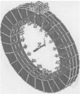
Figure 1. Meshing of the model of test block (G4 coated cutter) and friction ring (45# steel)
Figure 1 gives a schematic diagram of the meshed model of test block (G4 coated cutter) and friction ring (45# steel). When meshing the geometric model, due to the very small size of the coating, which is very different from the size of the substrate, adopting conventional modeling methods could result in too thin or deformed grids, so this paper chose to solve it by thinning the outer layer and then the meshes gradually become thicker as they approach toward the center. In addition, under the action of high temperature, the elastic moduli of the coating and the substrate are very different, thus the transition layer assumption had been proposed so that the coating and the substrate could be simulated more realistically based on the meshing of the transition layer and the gradually varied elastic modulus. When meshing the outer surface, the layer with densest meshed grids was defined as the first layer, then the meshed grids became thicker as they got closer to the center, the layer with the second densest meshed grids was defined as the second layer, and the grids in the third layer were meshed a bit denser. In this way, a relatively reasonable meshing system had been formed to attain more accurate results.
3.2 Boundary conditions
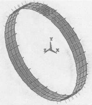
Whether the boundary conditions and the applied load are consistent with the actual engineering practice or not can directly affect the correctness and rationality of the analysis results. During the test, the test block (G4 coated cutter) was fixed by a clamper, the friction ring (45# steel) rotated at a certain speed and was subject to the action of a load P in the normal direction. According to requirements, the degrees of freedom of the test block in the X and Z directions were constrained, as for the friction ring, except for the rotational degree of freedom around Z axis, other degrees of freedom were all constrained as well. At the same time, a concentrated load P was applied to the nodes on the upper surface of the test block, and an angular velocity was applied to the friction ring. Figure 2 shows the boundary conditions and load applied on the test block (G4 coated cutter) and friction ring (45# steel)
Figure 2. Boundary conditions and load applied on the test block (G4 coated cutter) and friction ring (45# steel)
3.3 The applied friction force
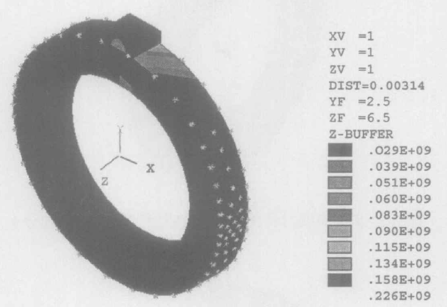
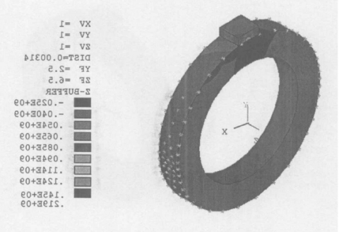
Since the focus of this paper is the stress analysis of coated cutting tools under high temperature friction, it’s very important to consider the action of high temperature and the adding of friction force. In the experiment, the friction pairs 170 and 174 in ANSYS were adopted, and the deformation caused by high temperature had been properly considered. The two contact surfaces were defined as friction contact surfaces, Figure 3 shows a schematic diagram of the friction pair.
Figure 3. The friction pair of test block (G4 coated cutter) and friction ring (45# steel)
3.4 Finite element calculation results and analysis
Figure 4 and Figure 5 are the finite element analysis results of the friction between test block (G2 coated cutter) and friction ring (45# steel) under high temperature friction (normal load P=70N, rotate speed $\omega=100 r / \min$), wherein Figure 4 is the principal stress, and Figure 5 is the shear stress.
(a) Maximum equivalent principal stress
(b) Profile of maximum equivalent principal stress
Figure 4. Principal stress of test block (G2 coated cutter) and friction ring (45# steel) under high temperature friction
(a) Shear stress
(b) Profile of shear stress
Figure 5. Shear stress of test block (G2 coated cutter) and friction ring (45# steel) under high temperature friction
(a) Maximum equivalent principal stress
(b) Profile of maximum equivalent principal stress
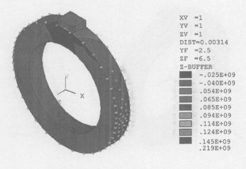
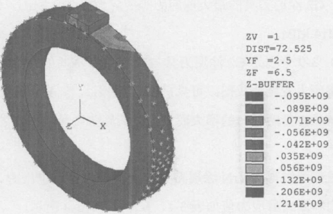
Figure 6. Principal stress of test block (G4 coated cutter) and friction ring (45# steel) under high temperature friction
(a) Shear stress
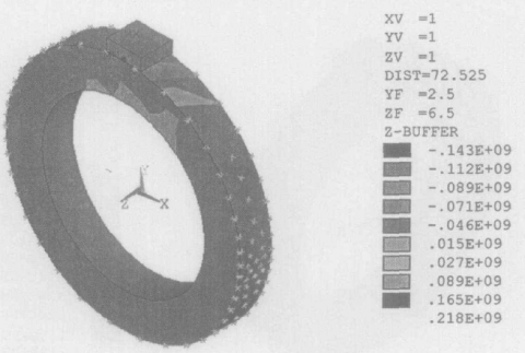
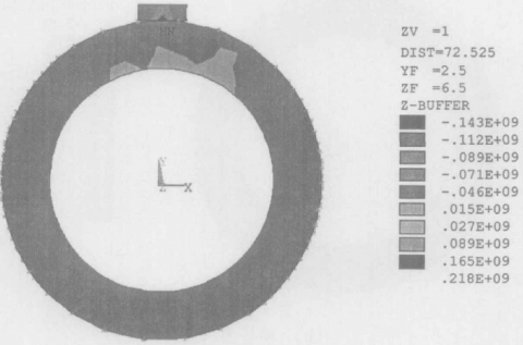
(b) Profile of shear stress
Figure 7. Shear stress of test block (G4 coated cutter) and friction ring (45# steel) under high temperature friction
Figures 6 and 7 are the finite element analysis results of the friction between test block (G4 coated cutter) and friction ring (45# steel) under high temperature friction (normal load P=70N, rotate speed $\omega=100 r / \min$), wherein Figure 6 is the principal stress, and Figure 7 is the shear stress.
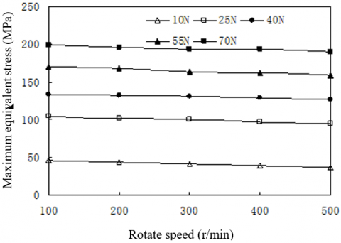
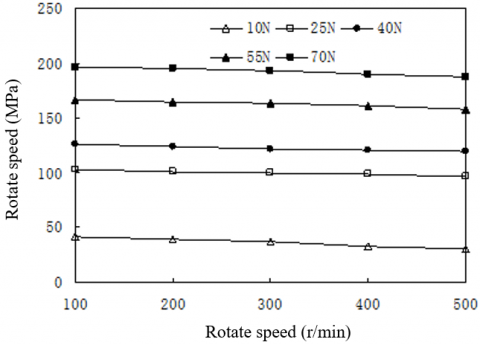
According to Figures 4(a) and 6(a), under high temperature friction, the equivalent stress on the center of the lower surface of the G2 and G4 test blocks was the maximum, then the value decreased gradually from the center to the outer part. The maximum equivalent stress of the G2 test block was 226MPa, and the maximum equivalent stress of the G4 test block was 218MPa. The stress acting on the Zr transition layer was decreased. According to Figures 5(a) and Figure 7(a), since the direction of the rotate speed was counterclockwise, in order to overcome the friction force and the constraint of the test block in the X direction, the shear stress in the left area of the center of the test block was the maximum, which gradually decreased from the maximum position to the outer part; the maximum shear stress of the G2 test block was 219MPa, and the maximum shear stress of the G4 test block was 214MPa. Figures 8 and 9 are the curves of the maximum equivalent stress and the maximum shear stress of the G2 test block and 45# steel friction ring under different friction conditions. According to the figure, when G2 test block rubbed against the 45# steel friction ring, both the maximum equivalent stress and the maximum shear stress increased with the rise of the load, and the trend was obvious. In contrast, the impact of rotate speed was relatively small. Similarly, the stress of ZrN-coated cutter when it rubbed against the 45# steel friction could be attained, and its maximum equivalent stress and maximum shear stress are listed in Tables 1-4.
Figure 8. The change of maximum equivalent stress with rotate speed when G2-coated cutter rubbed against 45# steel under high temperature friction
Figure 9. The change of maximum shear stress with rotate speed when G2-coated cutter rubbed against 45# steel under high temperature friction
Table 1. The maximum equivalent stress of the coating when ZrN-coated cutter rubbed against 45# steel under high temperature friction (rotate speed 100r/min)
|
Load Test block |
10 |
25 |
40 |
55 |
70 |
|
G1 |
98 |
147 |
188 |
239 |
302 |
|
T1 |
81 |
139 |
178 |
230 |
287 |
|
G2 |
69 |
128 |
163 |
198 |
226 |
|
T2 |
60 |
119 |
148 |
187 |
220 |
|
G4 |
71 |
135 |
159 |
200 |
218 |
|
T3 |
62 |
115 |
149 |
190 |
221 |
|
T4 |
58 |
116 |
129 |
175 |
208 |
|
T5 |
48 |
103 |
116 |
174 |
198 |
Table 2. The maximum shear stress of the coating when ZrN-coated cutter rubbed against 45# steel under high temperature friction and different loads (rotate speed 100r/min)
|
Load Test block |
10 |
25 |
40 |
55 |
70 |
|
G1 |
92 |
143 |
181 |
232 |
297 |
|
T1 |
81 |
137 |
175 |
230 |
282 |
|
G2 |
66 |
124 |
160 |
188 |
219 |
|
T2 |
54 |
118 |
146 |
187 |
217 |
|
G4 |
58 |
130 |
162 |
189 |
214 |
|
T3 |
60 |
114 |
148 |
179 |
219 |
|
T4 |
45 |
109 |
128 |
173 |
208 |
|
T5 |
39 |
98 |
109 |
167 |
206 |
Table 3. The maximum equivalent stress of the coating when ZrN-coated cutter rubbed against 45# steel under high temperature friction and different rotate speeds (load 70N)
|
Rotate speed (r/min) Test block |
100 |
200 |
300 |
400 |
500 |
|
G1 |
302 |
298 |
295 |
294 |
290 |
|
T1 |
287 |
285 |
274 |
276 |
276 |
|
G2 |
226 |
225 |
222 |
219 |
217 |
|
T2 |
220 |
217 |
216 |
214 |
211 |
|
G4 |
218 |
223 |
220 |
218 |
217 |
|
T3 |
221 |
216 |
215 |
214 |
210 |
|
T4 |
208 |
206 |
201 |
197 |
195 |
|
T5 |
198 |
202 |
197 |
194 |
212 |
Table 4. The maximum shear stress of the coating when ZrN-coated cutter rubbed against 45# steel under high temperature friction and different rotate speeds (load 70N)
|
Rotate speed (r/min) Test block |
100 |
200 |
300 |
400 |
500 |
|
G1 |
297 |
292 |
289 |
285 |
283 |
|
T1 |
282 |
277 |
277 |
275 |
274 |
|
G2 |
219 |
219 |
217 |
215 |
213 |
|
T2 |
216 |
212 |
213 |
209 |
207 |
|
G4 |
214 |
224 |
219 |
216 |
215 |
|
T3 |
219 |
216 |
215 |
214 |
209 |
|
T4 |
208 |
202 |
199 |
196 |
195 |
|
T5 |
194 |
200 |
195 |
192 |
209 |
Through above analysis, the laws of the stress when ZrN-coated cutter rubbed against 45# steel under high temperature friction could be summarized as:
(1) Under high temperature, both the maximum equivalent stress and the shear stress increased with the increase of load, the impact of load on stress was bigger, while the impact of rotate speed on stress was smaller.
(2) Under high temperature, from high to low, the rank of the maximum equivalent stress and maximum shear stress was G1>T1>T2>G4>T3>T4>T5, which was consistent with the laws of the wear rate of ZrN-coated cutting tools. The higher the stress on the ZrN-coated cutter, the greater the wear rate. The wear rate of uncoated cutter was greater than that of coated cutter; the coating layer had improved the wear resistance of the cutting tools. The wear rate of coatings with transition layer was smaller than that of coatings without transition layer. This is because in the process of friction and wear, the ZrN coating layer has high hardness and good wear resistance. Although the hardness of Zr is low, in the film layer, a hard layer is formed by the hard phase ZrN and the softer Zr on the surface of the hard alloy. According to the delamination theory of wear proposed by American scholar Suh, the soft Zr coating layer can decrease the plastic deformation of the underlying metal, reduce the generation and accumulation of dislocations, alleviate the formation, expansion, propagation, and connection of cracks caused by stress concentration, and delay the delamination of the bottom layer, thereby effectively improving the friction performance; the hard substrate ZrN can hardly generate plastic deformation, it can provide effective support to the soft coating layer so that it could exert its function better, and this is the reason for the good friction and wear performance of the coatings with transition layer.
(1) When ZrN-coated cutter rubbed against 45# steel under high temperature, both the maximum equivalent stress and the shear stress increased with the increase of load, and the increment was big; while the impact of rotate speed on the two was relatively small.
(2) The finite element analysis results of the stress state of block-ring friction under high temperature showed that, the stress of uncoated cutter was greater than that of coated cutter; and the stress of coatings with transition layer was greater than that without transition layer. In the experimental results, the stress value of T5 coated cutter was the smallest, therefore, the greater the stress of ZrN-coated cutter, the greater the wear rate.
[1] Polcar, T., Cavaleiro, A. (2014). High temperature behavior of nanolayered CrAlTiN coating: thermal stability, oxidation, and tribological properties. Surface and Coatings Technology, 257: 70-77. https://doi.org/10.1016/j.surfcoat.2014.07.053
[2] Meindlhumer, M., Jäger, N., Spor, S., et al. (2020). Nanoscale residual stress and microstructure gradients across the cutting edge area of a TiN coating on WCCo. Scripta Materialia, 182: 11-15. https://doi.org/10.1016/j.scriptamat.2020.02.031
[3] Nguyen, T.D., Kim, S.K., Lee, D.B. (2009). High-temperature oxidation of nano-multilayered TiAlCrSiN thin films in air. Surface and Coatings Technology, 204(5): 697-704. https://doi.org/10.1016/j.surfcoat.2009.09.008
[4] Chang, K.S., Zheng, G.M., Li, Y., et al. (2021). Effect of wet micro-blasting on surface integrity and cutting performance of coating tools for TC4 cutting. Materials Reports, 35(16): 16086-16092. https://doi.org/10.11896/cldb.20070196
[5] Al-Dabbas, M.A.A. (2021). The capability to make ice from sunlight utilizing a new absorption unit of nano-coated ammonia/calcium chloride. International Journal of Heat and Technology, 39(4): 1236-1242. https://doi.org/10.18280/ijht.390421
[6] Jacob, A., Gangopadhyay, S., Satapathy, A., et al. (2017). Influences of micro-blasting as surface treatment technique on properties and performance of AlTiN coated tools. Journal of Manufacturing Processes, 29: 407-418. https://doi.org/10.1016/j.jmapro.2017.08.013
[7] Nouari, M., Ginting, A. (2006). Wear characteristics and performance of multi-layer CVD-coated alloyed carbide tool in dry end milling of titanium alloy. Surface and Coatings Technology, 200(18-19): 5663-5676. https://doi.org/10.1016/j.surfcoat.2005.07.063
[8] Shi, Q., Li, L., He, N., Zhao, W., Liu, X. (2013). Experimental study in high speed milling of titanium alloy TC21. The International Journal of Advanced Manufacturing Technology, 64(1): 49-54. https://doi.org/10.1007/s00170-012-3997-3
[9] Ulutan, D., Ozel, T. (2011). Machining induced surface integrity in titanium and nickel alloys: A review. International Journal of Machine Tools and Manufacture, 51(3): 250-280. https://doi.org/10.1016/j.ijmachtools.2010.11.003
[10] Shin, S.H., Kim, C., Ahn, D.G., Kim, K.H., Kang, M.C. (2008). Oxidation behavior and cutting performance between Ti0.75-Al0.25-N and Ti0.69-Al0.23-Si0.08-N coated tool through measurement of cutting temperature. Materials Science Forum, 569: 141-144. https://doi.org/10.4028/www.scientific.net/MSF.569.141
[11] Konyashin, I.Y. (1995). PVD/CVD technology for coating cemented carbides. Surface and Coatings Technology, 71(3): 277-283. https://doi.org/10.1016/0257-8972(94)02325-K
[12] Fox-Rabinovich, G.S., Kovalev, A.I., Aguirre, M.H., et al. (2009). Design and performance of AlTiN and TiAlCrN PVD coatings for machining of hard to cut materials. Surface and Coatings Technology, 204(4): 489-496. https://doi.org/10.1016/j.surfcoat.2009.08.021
[13] Sproul, W.D. (1983). Very high rate reactive sputtering of TiN, ZrN and HfN. Thin Solid Films, 107(2): 141-147. https://doi.org/10.1016/0040-6090(83)90016-0
[14] Sue, J.A., Chang, T.P. (1995). Friction and wear behavior of titanium nitride, zirconium nitride and chromium nitride coatings at elevated temperatures. Surface and Coatings Technology, 76: 61-69. https://doi.org/10.1016/0257-8972(95)02506-5
[15] Ostrovskaya, Y.L., Strel'nitskij, V.E., Kuleba, V.I., Gamulya, G.D. (2001). Friction and wear behaviour of hard and superhard coatings at cryogenic temperatures. Tribology International, 34(4): 255-263. https://doi.org/10.1016/S0301-679X(01)00009-3
[16] Wang, Z.Y., Sahay, C., Rajurkar, K.P. (1996). Tool temperatures and crack development in milling cutters. International Journal of Machine Tools and Manufacture, 36(1): 129-140. https://doi.org/10.1016/0890-6955(94)00123-2
[17] Larijani, M.M., Tabrizi, N., Norouzian, S., et al. (2006). Structural and mechanical properties of ZrN films prepared by ion beam sputtering with varying N2/Ar ratio and substrate temperature. Vacuum, 81(4): 550-555. https://doi.org/10.1016/j.vacuum.2006.07.018
[18] Le, V.V., Nguyen, T.T., Kim, S.K. (2013). The influence of nitrogen pressure and substrate temperature on the structure and mechanical properties of CrAlBN thin films. Thin Solid Films, 548: 377-384. https://doi.org/10.1016/j.tsf.2013.09.041
[19] Yao, Y., Li, J., Wang, Y., Ye, Y., Zhu, L. (2015). Influence of the negative bias in ion plating on the microstructural and tribological performances of Ti–Si–N coatings in seawater. Surface and Coatings Technology, 280: 154-162. https://doi.org/10.1016/j.surfcoat.2015.09.005
[20] Yoon, S.Y., Yoon, S.Y., Chung, W.S., Kim, K.H. (2004). Impact-wear behaviors of TiN and Ti–Al–N coatings on AISI D2 steel and WC–Co substrates. Surface and Coatings Technology, 177: 645-650. https://doi.org/10.1016/j.surfcoat.2003.08.067
[21] Gurrappa, I. (2003). Characterization of titanium alloy Ti-6Al-4V for chemical, marine and industrial applications. Materials Characterization, 51(2-3): 131-139. https://doi.org/10.1016/j.matchar.2003.10.006
[22] Ferriere and, A., Lestrade, L. (2002). Solar Processing for the Glazing of ZrO2-Y2O3 Thermal Barrier Coatings: Reduction of Crack Initiation. Journal of Solar Energy Engineering, 124(3): 315-317. https://doi.org/10.1115/1.1488163
[23] Çalışkan, H., Küçükköse, M. (2015). The effect of aCN/TiAlN coating on tool wear, cutting force, surface finish and chip morphology in face milling of Ti6Al4V superalloy. International Journal of Refractory Metals and Hard Materials, 50: 304-312. https://doi.org/10.1016/j.ijrmhm.2015.02.012
[24] Wang, W.C., Li, J.X., Yuan, G.E., Kong, D.J. (2021). Structural characteristics and high-temperature tribological behaviors of laser cladded NiCoCrAlY–B4C composite coatings on Ti6Al4V alloy. Transactions of Nonferrous Metals Society of China, 31(9): 2729-2739. https://doi.org/10.1016/S1003-6326(21)65688-1
[25] Rafaja, D., Wüstefeld, C., Dopita, M., et al. (2014). Crystallography of phase transitions in metastable titanium aluminium nitride nanocomposites. Surface and Coatings Technology, 257: 26-37. https://doi.org/10.1016/j.surfcoat.2014.01.039