Roy J. Issa* | Emad Manla
© 2022 IIETA. This article is published by IIETA and is licensed under the CC BY 4.0 license (http://creativecommons.org/licenses/by/4.0/).
OPEN ACCESS
The feasibility of using paraffin wax as a phase change material was investigated in the design of a solar tracking mechanism for the positioning of photovoltaic panels for improved solar energy harnessing. Tests were conducted under the climatic conditions of Canyon, Texas. To investigate the feasibility of the solar tracking system, the performance of the system was compared against a stationary system where the PV panel was tilted at 35o with respect to the horizontal surface for the month of May. Tests conducted on paraffin wax show a steep increase in the wax volume expansion as the wax transitions from solid to liquid. The expansion is shown to markedly decrease with the increase in the actuator loading for which a higher temperature is needed to achieve a desired actuator displacement. Performed tests show the solar tracking system resulted in 22% enhancement in solar energy harnessing compared to the stationary system. It is also shown that as the paraffin wax melts and then solidifies, the actuator extension and retraction appears to follow a hysteresis loop.
thermal actuator, phase change material, paraffin wax, solar tracking, photovoltaic panel
Phase change actuators are actuators that transform thermal energy into mechanical work through the utilization of a phase change material (PCM). Paraffin wax has attracted significant interest as a phase change material due to being chemically inert, having very low compressibility, inexpensive and readily accessible material. Paraffin actuators utilize the volume change associated with the wax phase transformation from solid to liquid to deliver both a large stroke and a high force. Open literature data reveal that its volume expansion during phase change can range between 10 to 15%. Owing to that, paraffin-based actuators are shown to have high-energy density, defined as the output work per unit volume. Figure 1 shows the energy density of various types of actuating materials. PCM [1] stands the highest among actuating materials. This is followed by shape memory alloys (SMA) [2], thermo-pneumatic [3], electromagnetic [4], electrostatic [5], piezoelectric [6] and muscle [7] materials.
Figure 1. Energy density for various types of actuators
Paraffin wax actuators employ either membrane displacement or piston motion. Membrane-type actuators consist of an elastic diaphragm and a compartment that holds the paraffin wax. When the wax is heated, it expands forcing the diaphragm membrane to displace which returns to its original shape after cooling. These actuating mechanisms are widely used in applications such as valves, heat switches, microfluidics, MEMS, and solar trackers [8]. Novak et al. [9] and Pauken et al. [10] designed a paraffin-actuated gas-type heat switch to remove excess heat from the Mars Rover battery during daytime, and to provide insulation to the battery during the cold night. Lee and Lucyszyn [11] analyzed the performance of micromachined electrothermal hydraulic microactuators using paraffin wax enclosed within micromachined silicon containers, and calculated the hydraulic pressure of the expanding wax using the theory of large deflections. Tremblay et al. [12] presented a demonstration of a reversible in-plane actuator that is activated by sunlight for self-tracking solar concentrator. The actuating mechanism consisted of a polycarbonate honeycomb array with 2.3 mm and 0.75 mm cells filled with paraffin-carbon composite material producing a maximum deflection of 64 mm and 51 mm, respectively. Liu et al. [13] designed a microactuator with induction heating using PCM composite that consisted of paraffin wax, expanded graphite and nickel particles exhibiting high electrical conductivity and magnetic permeability. The actuator’s polydimethylsiloxane diaphragm was capable of producing 142 mm actuation height with the application of 1.42 W of induction heating.
Piston-type actuators are intended to produce large displacements. Kabei et al. [14] designed a piston-cylinder type microactuator to be used in endoscopic surgery. The actuator whose outer diameter and length were 2.5 mm and 130 mm, respectively, was capable of producing a stroke of 8 mm against a 1kg load. Tibbitts [15] designed a piston-cylinder type paraffin wax actuator for use in aerospace mechanisms. The 30 g actuator was capable of producing a stroke of 10 cm and an output force of 4,000 N. Bodén et al. [16] designed a piston-cylinder actuator 8 mm long and 2 mm in diameter capable of producing a displacement of 140 mm at a counter force of 2.6 N. A larger actuator of 20 mm diameter and 90 mm length was designed by Mallet and Kornmann [17] for space applications that produced a stroke of 20 mm under a high load of 1000 N. Chen et al. [18] studied the factors influencing thermal hysteresis in paraffin piston-cylinder actuators. It was found that in order to reduce the degree of thermal hysteresis in paraffin, the wax cooling speed needs to be the slowest and the actuator resetting spring needs to have the least stiffness.
Ho et al. [19] studied the dynamic response of a thermally actuated paraffin actuator to examine the melting heat transfer characteristics and the displacement behavior of the molten wax moving wall. Their results show the melting rate of paraffin and thus the actuator speed was fast at the beginning of the actuation but gradually slowed as time progressed. The melting time was shown to increase as the subcooling of paraffin wax increased. A compact actuator without sealed moveable parts was designed by Mann et al. [20]. Forces of up to 63 kN were achieved for an actuator of 30 mm in diameter and 7 mm in height. Compared to existing actuators, an increase in performance by a factor of up to 7 was achieved. Mendecka et al. [21] assessed the possibility of using the mechanical work produced by the volumetric expansion of paraffin-based actuators for photovoltaic solar tracking. Using a 2D finite-difference/finite-volume numerical approach, they developed a model to evaluate the temperature and density fields inside the phase change material. Their simulation results for the ambient conditions of Southern Italy showed an average daily volumetric expansion of 3.1% during summer and 2.5% during winter, allowing the tracking of nearly 90 PV panels having 1.6 m2 surface area each.
The utilization of paraffin wax has been recently implemented in the design of thermally-driven passive solar trackers, referred to as HelioDrive [22]. The system employs a piston that pushes a cam tube with helical cuts translating the linear motion into a rotational motion. The receiver consists of a paraffin actuator encapsulated inside a glass insulator tube. The receiver is positioned on top of a lower assembly (consisting of the tube with helical cuts) that is anchored to the ground. A parabolic-shaped concentrator directs incident solar radiation to the receiver, resulting in the assembly moving upward and rotating westward as the photovoltaic (PV) panel follows the movement of the sun from east to west. The total panel capacity to track ranges from 120 to 1,200 panels in a ground mount.
The above review shows the majority of piston-type paraffin wax actuators were implemented in applications such as surgery, aerospace mechanisms, and the positioning of valves and switch. These actuators were shown to produce an output load that ranges from around 200 kPa to 125,000 kPa. However, very few studies have been conducted on the use of paraffin-wax actuators in the solar tracking of PV panels. The few studies performed were those by Tremblay et al. [12], Mendecka et al. [21], in addition to the commercially available HelioDrive Technology [22]. In the design by Tremblay et al., the actuating mechanism was a polycarbonate honeycomb array, while in the study by Mendecka et al. technical assessment was conducted on the thermal expansion of paraffin-based actuators for passive solar tracking. Except for the commercial HelioDrive system, none of these published studies particularly implemented paraffin-wax piston-type actuators in the solar tracking of PV panels nor investigated the dynamic response of this type of actuation in such an application.
The purpose of this paper is to provide a proof of principle demonstration of thermally-actuated solar tracking mechanism for PV panels using paraffin-based actuators. The authors aim to investigate the effect changes in ambient temperature have on the dynamic response of a paraffin-based actuator when implemented in solar tracking. The study will examine the effect piston loading and temperature have on the thermal expansion of the wax. The study’s findings will ultimately shed light on whether a paraffin-based actuator is a feasible alternative to the commonly available single-axis electrically-driven solar tracker.
In this paper, the design of the solar tracking mechanism is presented in Section 2, the experimental setup. Section 3 presents the design of the paraffin wax actuator along with performed tests to determine the effect actuator loading and temperature have on wax thermal expansion. The results will show that as the actuator loading increases, a higher wax temperature is needed to produce a desired piston displacement. In Section 4, tests were performed on the solar tracking mechanism to evaluate its performance under the climatic conditions of West Texas. These tests will show a noticeable enhancement in the incident solar insolation for the implemented solar tracking mechanism in comparison to a stationary system in which the PV panel is oriented at an optimal seasonal angle. The results will portray the dynamic response of the paraffin-wax actuator to ambient temperature variations, and will show the hysteresis effect associated with the actuator expansion and retraction as function of temperature. Finally, in Section 5 a summary and conclusion are presented.
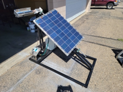
Figure 2 shows the overall setup of the experimental system. The system consists of a solar tracking mechanism that is driven by a PCM actuator for the positioning of a PV panel for improved solar energy harnessing. A 1.5 m long stainless steel shaft of 0.02 m diameter is being used to rotate the PV panel. A triangular frame is constructed to support the PV panel and the shaft at an angle of 35º with respect to the horizontal surface. An optimal angle of 35º was chosen based on the geographical latitude of Canyon, Texas for the month of May.
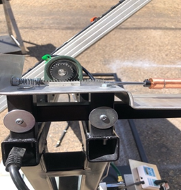
As a rule of thumb, the solar panel tilt angle is set to the geographical latitude of the location for optimal solar energy harnessing [23]. It was estimated that for the geographical latitude of Canyon, a surface with a fixed tilt angle of 35o would receive about 70% of the maximum solar radiation intensity throughout the year. In order for the PV panel to adequately follow the sun, a rack and pinion gear system (Figure 3) is employed to transfer the linear motion of the piston/cylinder actuator to a rotational motion. The rack and pinion gear system is designed to provide a maximum rotation of 120o for the PV panel as it tracks the sun from sunrise to sunset. At sunset, a steel spring located at the end of the thermal actuating device (shown in Figure 3) resets the actuating piston to its original position, thus rotating the panel back to sunrise position. The PV panel is directly attached to a rotating shaft that is supported by two bearings. The upper end of the shaft was machined down to 0.01 m to allow for the installation of the pinion. A keyway was machined to properly hold the pinion in place. The PV panel is mounted onto the shaft using U-bolts. A solar reflector has been utilized to focus the incident solar radiation onto the actuator.
To achieve a rotation of 120o, the relationship between the rack maximum linear displacement, smax, and the pinion gear parameter, P, was set to a ratio of 1:3, such that:
$P=3 s_{\max }$ (1)
According to Eq. (1), the pinion circumference and diameter were 7.62 cm and 2.43 cm, respectively.
Figure 2. Overall setup of the solar tracking system
Figure 3. Rack and pinion gear system
The horizontal force acting on the rack, Fr, consists of: the force due to the sliding of the effective mass of the combined solar panel and mechanism frame over the guide rail, the inertial force due to the acceleration of the effective mass, and the external force due to the loading of the spring in addition to the wind force that may be acting on the frame:
$F_{r}=m_{e} g \mu+m_{e} a+F_{e}$ (2)
A digital force sensor (Baoshishan ZP-500 N model) was used to experimentally determine the horizontal force portrayed by Eq. (2). The sensor was temporarily placed in the location of the actuator to determine the magnitude of the force needed to rotate the solar panel and the mounting frame. Results are shown in Figure 4 for the case of with and without the application of a resetting spring. The rack force is shown to decrease with the increase in the rotation of the solar panel mechanism. With the implementation of a resetting spring, the rack force is shown to noticeably increase due to the loading of the spring. In the presence of a spring, the rack is shown to be subjected to a minimum force of 100 N for a horizontal displacement of 9 mm. With further displacement, the required force is shown to start to increase due to the compression of the spring.
Figure 4. Rack force as function of rack horizontal displacement
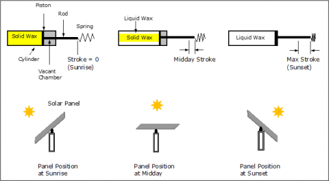
As incident radiation heats the paraffin actuator, wax starts melting. This phase change generates a force due to the wax expanding volume, and this force is transmitted to the actuating piston. The piston starts to move the rack once enough force is generated. This in turn causes the pinion gear to rotate resulting in the rotation of the shaft and PV panel as the panel tracks the sun throughout the day. The melting of the wax is a slow process that results in gradual rotation of the PV panel as it emulates sunflower’s tracking of the sun. The process is illustrated in Figure 5.
Figure 5. Operation of the solar drive system
The paraffin wax actuator is a piston/cylinder type of an actuator. Its schematics is shown in Figure 6. Paraffin wax is encapsulated inside a copper tube with the help of a flexible rubber/cork seal. The tube inner and outer diameters are 1.45 and 2.23 cm, respectively. The actuator uses a stainless steel rod of 5 mm in diameter. The wax height inside the tube is 40.64 cm at room temperature. As the tube gets heated, the expanding wax causes the piston to displace. Paraffin wax (CnH2n+2) is a mixture of saturated alkanes and hydrocarbons. The type of paraffin wax used in this application is Gulf Wax, a food grade wax with a melting point temperature between 46 and 68℃, a material density of 900 kg/m3, a volumetric thermal expansion coefficient of 0.000764 K-1, and a bulk modulus of 2 GPa. The volume expansion of the wax, ev, is related to the actuator stroke, s, as follows:
$\varepsilon_{v}=\frac{\Delta V}{V_{o}}=\frac{S}{h_{o}}$ (3)
The unloaded cylinder stroke is related to the temperature increase of the wax, DT, through the wax thermal expansion coefficient, b:
$s=h_{o}\left[(1+\beta \Delta T)^{3}-1\right]$ (4)
Figure 6. Design of the paraffin wax actuator
Figure 7. Experimental testing of the paraffin wax actuator
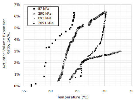
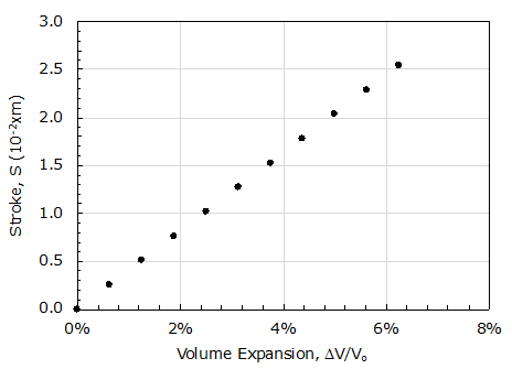
Experimental tests were conducted on the actuator to determine the effect temperature and pressure have on the volume expansion of the wax inside the actuator. Figure 7 shows a sketch of the testing procedure. The actuator was heated by inserting it vertically into a water bath with a controlled temperature setting. A digital force sensor with a rail guide (Baoshishan ZP-500 N model) was used to determine the force exerted by the expanding wax. As the wax temperature increased, a turn wheel on the sensor stand was rotated to keep the pressure generated by the expanding wax constant. Figure 8 shows the volume expansion ratio of the wax as function of temperature and applied pressures (87, 390, 693 and 2691 kPa). The data shows a steep jump in the thermal expansion as the wax transitions from solid to liquid, which is a general property of long-chained polymers. As the loading pressure increases, a higher temperature is required to achieve a desired wax expansion. The wax expansion is shown to considerably decrease with the increase in loading as shown for the case of 2691 kPa. Using Eqns. (3) and (4), the piston stroke can be calculated as function of the paraffin wax volume expansion ratio as shown in Figure 9. In a cylindrical geometry where expansion occurs in the axial direction, the relationship between the wax volume expansion and the actuator stroke is a linear one as depicted by Figure 9. Based on the geometry of the actuator, a 6.25% wax expansion results in a piston stroke of 2.54 cm.
Figure 8. Paraffin actuator volume expansion as function of temperature and pressure
Figure 9. Actuator stroke as function of paraffin wax volume expansiona
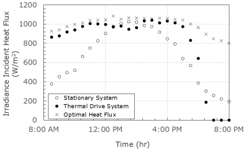
Tests were conducted to evaluate the performance of the solar tracking mechanism under the climatic conditions of Canyon, Texas. The performance of the system was compared against a stationary system where the PV panel was oriented at the optimal seasonal angle of 35o for the month of May. The results are shown for the test conducted on May 2, 2021. Figure 10 shows typical results of the time history of the solar insolation (solar radiation intensity) in a 12-hour daylight period for the solar tracking and stationary systems along with the optimal heat flux that can be captured. The optimal heat flux is determined by positioning the solar irradiance meter (Seaward Model No. SS200R) at an angle with respect to the incident radiation that captures the maximum amount of incident solar heat flux. The conditions of the test were as follows. The average wind speed on the day of this test ranged from 5.5 to 9.4 m/s, the average ambient temperature ranged from 12.8 to 34.4℃, and the average relative humidity ranged from 14% to 67%. Solar radiation intensity is shown to reach a peak slightly above 1000 W/m2. The data in Figure 10 shows the solar tracking system to outperform the stationary system particularly during the morning hours from 8:00 am to 12:00 pm. It should be noted here that the skies were clear most of the day with only limited cloud coverage. The actuator slightly fell behind between 1:00-2:00 pm but quickly caught up in the afternoon where it produced good results until about 6:00 pm. After 6:00 pm, the thermal actuator cooled down fast and began to rotate back towards the sunrise position. This caused a sharp decline in the incident heat flux during the final two hours. Figure 10 shows the solar tracking system follows closely the optimal heat flux for good number of hours in comparison to the stationary system.
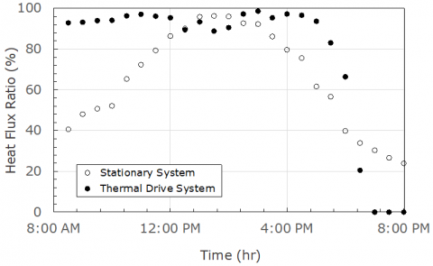
Figure 11 shows the relative heat flux of the solar tracking and stationary systems. The relative heat flux is the ratio of the system heat flux to the optimal heat flux. The solar tracking system had an average heat flux ratio of 0.82, while the stationary system had an average ratio of 0.67. It is found that the solar tracking system performed 22% better than the stationary system in capturing the incident solar heat flux.
Figure 10. Incident solar panel heat flux versus time
Figure 11. Heat flux ratio versus time
Figure 12. Actuator and ambient temperature versus time
Figure 13. Thermal actuator piston displacement versus time
Figure 14. Piston displacement versus actuator temperature
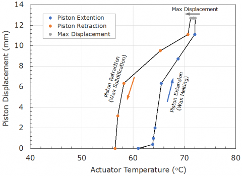
Figure 12 shows the ambient and actuator surface temperatures, and Figure 13 shows the displacement of the actuator piston as function of time. It is shown that during the early morning hours, it takes the actuator few hours to warm up to the melting temperature of the, even though some wax expansion does occur as temperature increases in the solid phase. The copper actuator surface was coated with black paint to improve its solar absorptivity. Because of that, it is seen that as the ambient temperature increases during the day to 34℃, the actuator surface temperature sharply increases to reach 73℃ in the afternoon hours. However, as the incident solar heat flux decreases in the late afternoon (Figure 10), the surface temperature of the actuator quickly drops to the ambient temperature. Figure 13 shows the actuator to produce a maximum stroke of 12.7 mm as the actuator temperature reaches 73℃. The stroke is shown to hold steady at 12.7 mm for few hours until the incident heat flux starts to decrease. Figure 14 shows the piston displacement as function of the actuator temperature. The piston extension and retraction is shown to follow a hysteresis loop as the wax melts and then solidifies inside the actuator. As the actuator reaches its maximum temperature, its maximum extension is also reached. As the actuators starts cooling, the piston appears to hold a steady position until the temperature drops below the onset of solidification where any further decrease in the actuator temperature results in a sharp retraction of the piston.
A thermally-actuated solar tracking mechanism was designed for the positioning of PV panels for improved solar energy harnessing. The study investigated the feasibility of using paraffin wax as a phase change material inside a piston/cylinder actuator. The wax was encapsulated inside a copper tube actuator with the help of a flexible sealant. The performance of the system was compared against a stationary system where the PV panel was oriented at a fixed optimal seasonal angle of 35o for the month of May in Canyon, Texas, and it was also compared against the optimal heat flux that can be harnessed using a solar irradiance meter. The study sheds light on the dynamic response of a paraffin-wax actuator in its implementation as a single-axis solar tracker. Test data reveal the effect ambient temperature has on the displacement of the actuator. Based on the results of the study, the following conclusions were reached:
Compared to a stationary system, the enhancement in solar energy harnessing reported in this study is not far off from that reported by HelioDrive [22]. Paraffin wax incorporated in a piston-type actuator is shown to produce sufficient piston displacement (and force) for it to be used as a solar tracker. However, the system analyzed in this paper had some drawbacks:
The authors would like to thank the following students from the mechanical engineering program at West Texas A&M University for their contribution to this project: Cade Engle, Jesus Rayos, Will Scroggins, Diego Valencia, and Andrew Alarcon.
|
$a$ |
panel acceleration, m.s-2 |
|
$F_{e}$ |
external force, N |
|
$F_{r}$ |
horizontal force acting on the rack, N |
|
$g$ |
gravitational acceleration, m.s-2 |
|
$h_{o}$ |
solid-state height of the wax inside the actuator, m |
|
$m_{e}$ |
effective mass of the solar panel mechanism, kg |
|
$P$ |
pinion gear parameter, m |
|
$s$ |
rack displacement, m |
|
$s_{\max }$ |
rack maximum displacement, m |
|
$V_{o}$ |
solid-state volume of the wax inside the actuator, m3 |
|
Greek symbols |
|
|
$\beta$ |
wax thermal expansion coefficient, K-1 |
|
$\varepsilon_{v}$ |
volume expansion of the wax |
|
$\Delta T$ |
change in temperature, K-1 |
|
$\Delta V$ |
change in volume, m3 |
|
$\mu$ |
guide rail coefficient of friction |
[1] Pan, R. (2013). Energy density and volume expansion in solid-liquid phase change for energy applications. M.S. Thesis, Kth School of Industrial Engineering and Management, Energy Technology, Stockholm.
[2] Krulevitch, P., Lee, A.P., Ramsey, P.B., Trevino, J.C., Hamilton, J., Northrup, M.A. (1996). Thin film shape memory alloy microactuators. Journal of Micro-electromechanical Systems, 5(4): 270-282. https://doi.org/10.1109/84.546407
[3] Zdeblick, M.J., Anderson, R., Jankowski, J., Kline-Schoder, B., Christel, L., Miles, R., Weber, W. (1994). Thermopneumatically actuated microvalves and integrated electro-fluidic circuits. Technical Digest of the 1994 IEEE Solid-State Sensor and Actuator Workshop, Hilton Head Island, South Carolina. https://doi.org/10.31438/trf.hh1994.57
[4] Guckel, H., Christenson, T.R., Earles, T., Klein, J., Zook, J.D., Ohnstein, T., Karnowski, M. (1994). Laterally driven electromagnetic actuators. Technical Digest of the 1994 Solid-State Sensor and Actuator Workshop, Hilton Head Island, South Carolina. https://doi.org/10.31438/trf.hh1994.11
[5] Fan, L.S., Woodman, S.J., Moore, R.C., Crawforth, L., Reiley, T.C., Moser, M.A. (1994). Batch fabricated area-efficient milli-actuators. Proceedings of the IEEE Solid-State Sensor and Actuator Workshop, Hilton Head Island, South Carolina. https://doi.org/10.31438/trf.hh1994.9
[6] Robbins, W.P., Polla, D.L., Tamagawa, T., Glumac, D.E., Judy, J.W. (1991). Linear motion microactuators using piezoelectric thin films. Proceedings of the IEEE Conference on Solid-State Sensors and Actuators, San Francisco, California. https://doi.org/10.1109/SENSOR.1991.148798
[7] Hunter, I.W., Lafontaine, S. (1992). A comparison of muscle with artificial actuators. Technical Digest of IEEE Solid-State Sensor Actuator Workshop, Hilton Head, South Carolina, pp. 178-185. https://doi.org/10.1109/SOLSEN.1992.228297
[8] Gulfam, R., Zhang, P., Meng, Z. (2019). Advanced thermal systems driven by paraffin-based phase change materials – a review. Applied Energy, 238: 582-611. https://doi.org/10.1016/j.apenergy.2019.01.114
[9] Novak, K., Sunada, E., Lankford, K., Pauken, M., Birur, G. (2002). Wax actuated heat switch development for Mars exploration rover. 13th Spacecraft Thermal Control Technology Workshop, El Segundo, California.
[10] Pauken, M., Sunada, E., Novak, K., Phillips, C., Birur, G. (2002). Development testing of a paraffin-actuated heat switch for Mars rover applications. 32nd International Conference on Environmental Systems, San Antonio, Texas. https://doi.org/10.4271/2002-01-2273
[11] Lee, J.S., Lucyszyn, S. (2007). Design and pressure analysis for bulk-micromachined electrothermal hydraulic microactuators using a PCM. Sensors and Actuators A, 133(2): 294-300. https://doi.org/10.1016/j.sna.2006.06.018
[12] Tremblay, E.J., Loterie, D., Moser, C. (2012). Thermal phase change actuator for self-tracking solar concentration. Optics Express, 20(S6): 964-976. https://doi.org/10.1364/OE.20.00A964
[13] Liu, B., Yang, J., Zhang, Z., Yang, J., Li, D. (2018). A phase change microactuator based on paraffin wax/expanded graphite/nickel particle composite with induction heating. Sensors and Actuators A: Physical, 275: 129-136. https://doi.org/10.1016/j.sna.2018.04.006
[14] Kabei, N., Nosuda, M., Kagamibuchi, H., Tashiro, R., Mizuno, H., Ueda, Y., Tsuchiya, K. (1997). A thermal-expansion-type microactuator with paraffin as the expansive material (Basic performance of a prototype linear actuator). JSME International Journal, Series C, 40(4): 736-742. https://doi.org/10.1299/jsmec.40.736
[15] Tibbitts, S. (1988). High output paraffin actuators: Utilization in aerospace mechanisms. The 22nd Aerospace Mechanisms Symposium, Hampton, Virginia.
[16] Bodén, R., Lehto, M., Schweitz, J. (2006). A paraffin driven linear microactuator for high force and large displacement applications. Proceedings of the 10th International Conference on New Actuators & 4th International Exhibition on Smart Actuators and Drive Systems, Bremen, Germany.
[17] Mallet, O., Kornmann, M. (1997). Development of a paraffin actuator. Proceedings of the 7th European Space Mechanisms and Tribology Symposium, ESTEC, Noordwijk, The Netherlands.
[18] Chen, B., Liu, Y., Zhang, X., Sun, C. (2008). Study on influence factors of thermal hysteresis in paraffin actuator. 2008 International Conference on Intelligent Computation Technology and Automation, Changsha, China, pp. 1145-1148. https://doi.org/10.1109/ICICTA.2008.272
[19] Ho, C.J., Wang, W.J., Lai, C.M. (2016). Dynamic response of a thermally activated paraffin actuator. International Journal of Heat and Mass Transfer, 103: 894-899. http://dx.doi.org/10.1016/j.ijheatmasstransfer.2016.07.104
[20] Mann, A., Germann, T., Ruiter, M., Groche, P. (2020). The challenge of upscaling paraffin wax actuators. Materials and Design, 190: 1-9. https://doi.org/10.1016/j.matdes.2020.108580
[21] Mendecka, B., Di Ilio, G., Krastev, V.K., Bella, G. (2022). Technical assessment of phase change material thermal expansion for passive solar tracking in residential thermal energy storage applications. Journal of Energy Storage, 48: 1-8. https://doi.org/10.1016/j.est.2022.103990
[22] Sulas Industries. https://www.sulasindustries.com, accessed on March 11, 2022.
[23] Gevorkian, P. (2008). Solar Power in Building Design, 1st edition. McGraw-Hill, USA, Chapter 4. https://energyeducation.ca/encyclopedia/Solar_panel_orientation.