Jitendra Singh Pal* | Shivalingappa Nagappa Sapali | Anil Tumkur Ramakrishna | Niyaj Dilavar Shikalgar | Ajit Shinde
© 2022 IIETA. This article is published by IIETA and is licensed under the CC BY 4.0 license (http://creativecommons.org/licenses/by/4.0/).
OPEN ACCESS
Auxiliary boilers onboard motor ships are the subject of ongoing research. Steam is produced by an auxiliary boiler for fuel heating and cargo oil pumping turbines. This marine boiler is a pressure jet burner water tube auxiliary boiler with a 70-80% efficiency rating. The goal of determining the process and components of irreversibility loss in a system is to identify the process and components of exergy losses. The second law of thermodynamics and the concept of irreversible entropy production are the foundations of this study's exergy technique of analysis. This concept of considering entropy at a given steady-state condition rather than as a change in a process is also one of the features of this exergy analysis of the marine oil-fired boiler. The exergy loss in the combustion chamber was calculated and determined to be 35024 kJ, which is the maximum irreversibility in this maritime auxiliary boiler. A numerical analysis of the current nozzle jet burner is undertaken to evaluate the enhancement of the combustion process. The temperature and velocity contour of the fuel stream passing through the nozzle of this auxiliary boiler's burner depicts atomization.
exergy, irreversibility, numerical analysis, rational efficiency, steam atomization
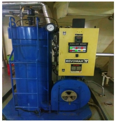
The Revomax is the newest member of the family of oil-type coil-type steam generators. The reverse-flue membrane coil, which has three passes, is a mix of tried-and-true heat transmission mechanisms. The steam is used to close the gland and heat the fuel. This boiler uses an optimizer to keep the feedwater temperature below 70℃. This boiler runs on High-Speed Diesel (HSD), which is delivered by an internal gear pump.
The requirement to improve the efficiency of energy usage should guide the application of exergy analysis to a system. Tsatsaronis [1] specifies many exergy analysis and exergy costing terminologies, discusses symbol options for exergy and other exergoeconomic variables, and provides phrasing for the remaining terms. According to Som and Datta [2] the main technique for controlling exergy destruction in a combustion process is to reduce irreversibility in heat conduction by properly controlling physical phenomena and chemical reactions. They were able to find the ideal operating condition in their parametric analysis of combustion irreversibility using operational parameters in various types of flames. However, it is thought that Aljundi's [3] exergy (second law) analysis of Jordan's steam power plant, where the boiler is the principal source of irreversibility, will be influenced by the dead situation. Saidur et al. [4] investigated the most common source of exergy loss in boilers, which may be mitigated by preheating the combustion air and reducing the air-fuel ratio. The boiler's energy and exergy efficiencies are 72.46% and 24.89%, respectively. The combustion chamber, followed by the heat exchanger in a boiler system, has been shown to be the most significant source to exergy loss. Internal thermal energy exchange, which is linked to high-temperature gradients caused by heat release in combustion reactions, is a major source of irreversibility. Bundnik and Stanek [5] examined the impact of system parameters on exegetic cost indices in a steam boiler. The computations are carried out on a unit of a modern Polish power plant. Several conclusions have been drawn based on the findings, demonstrating the benefits of using exergetic cost assessments. In their paper, Hajidavalloo and Vosough [6] examined at the energy and exergy efficiency of a supercritical power generation. The impact of the weather on condenser pressure was investigated. Ohijeagbon et al. [7] describe the energy and exergy assessments of industrial steam boilers. A methodology for analysing thermodynamic exergy qualities and exergy input and output resources was developed for industrial steam boilers. According to Taillon and Blanchard [8] boosting thermal energy efficiency improves overall exergy efficiency just marginally. According to Abdulrahmanet et al. [9], the highest value of exergy loss in shell and tube type heat exchangers is 42 W when baffles are present. Finally, the heat exchanger with baffles outperforms the heat exchanger without baffles in terms of hydraulic and thermal performance.
Gulotta et al. [10] observed hotspots in the biomass boiler, where recoverable exergy accounts for 17.4% of total exergy destroyed. Enebe and Odukwe [11] presented those variations in boiler inlet pressure showed that when boiler inner pressure increased, the rate of exergy loss decreased. Various studies on thermal power plants have been evaluated and major conclusions have been provided in this work by Ahmadi et al. [12]. For examining power plants, several analyses have been used, including energy, exergy, and economic assessments [13]. The flow parameters and physical behaviours of particles through nozzles have been numerically examined, as shown by Pal et al. [14, 15]. According to a computational fluid study of combustion, inappropriate air circulation causes reduced heat transfer at the water tubes boiler. Using energy and exergy analysis to construct a boiler mathematical model is one of the most successful methods. Pal et al. [16] calculates the amount and distribution of unavailable work in the evaporator, condenser, and brine section of a plate-type freshwater generator. The exergy and exergo-environmental analysis of the 660 MW supercritical coal-fired plant in western India is presented in this paper by Nikam et al. [17]. When compared to subcritical coal-fired power plants, supercritical coal-fired power plants have proven to be a superior technology. Khaleel et al. [18] developed a 'Predictive Model' to forecast coal-fired power plant energy and exergy-based behaviour. Swirling in the flame jet increases the average heat flux by up to 179.2%, according to Badiger's et al. [19] research. Tarla et al. [20] look into ways to reduce exergy loss in boiler components such boilers, turbines, and condensers. Experimental results have verified the use of heat exchanger for steam condensation. The enthalpy-entropy diagram was used to show the results of a power plant's exergy study in Ahern's [21] "book on the exergy method of energy systems analysis". "Availability is the highest quantity of work obtainable from the combined system as the control mass is brought into harmony with the environment," according to Moran [22]. The author builds a thermodynamic exergy load and estimates the rational efficiency of thermal plant components in Kotas' book [23].
The first law of thermodynamics is often used to analyse energy usage, according to the literature study, but it fails to account for the quality component of energy. Exergy analysis comes into play at this point. According to the literature, exergy is a quality that allows you to determine the useable work potential of a given amount of energy in a specific state. In addition, less study is carried out for the auxiliary boiler employed in marine vessels.
Figure 1. Experimental setup of auxiliary boiler
The goal of this research is to look at the exergetic performance of oil-fired marine boilers, as well as the numerical investigation of pressure jet burners and the effects of various thermodynamic and operational variables. (Refer to Figure 1 and Table 1). Another important aspect of this study is to identify the components of higher exergy loss. The basic computation of exergy losses is shown in Table 2, which displays exergy losses qualitatively and quantitatively for each process. The block method of exergy computation uses the main performance metrics of the energy system, such as the values of exergy at the start and end of the process under consideration in the block. A CFD analysis of the burner nozzle and data collection from intern cadets are used to validate the system.
Table 1. Specifications used in the experimental work
|
Components |
Description |
|
Burner |
Jet type |
|
Tube |
Water tube |
|
Economizer |
Shell and tube type |
|
Optimizer |
Tubular type |
|
Temperature range |
30° to 180℃ |
|
Accuracy |
±2℃ |
Table 2. Exergy analysis of sub-region of marine boiler
|
Region |
Exergy Input |
Exergy Output |
Exergy loss |
Exergy eff. |
|
|
kW |
kW |
kW |
|
|
A |
2.12 |
0.99 |
1.13 |
47% |
|
B |
2.88 |
0.1 |
2.78 |
3% |
|
C |
45417 |
10393 |
35024 |
23% |
|
D |
10278 |
789.15 |
9488 |
7% |
|
E |
576.17 |
115.09 |
461 |
20% |
The study is motivated by the fact that the challenges in energy analysis are also because it only analyzes energy amounts and ignores energy quality, which is constantly degraded during real processes. Exergy analysis solves a lot of the issues that come with energy analysis. The reference point for temperature and pressure of all fluids is TO=20℃ and PO =1.0 atm in this study for exergy analysis. The auxiliary boiler's feedwater enters through the feed controller and flows through the economiser inlet header. After gaining heat, heated feedwater continues to the optimizer tube header, then to the water tubes, and finally to the furnace on all sides (tubes). The water in these tubes rises and exits as a mixture of steam and water, which enters the drum through risers (tubes) where steam and water are separated and escapes to the main steam stop valve.
The exergy loss of the auxiliary boiler is found out in this investigation. The fuel, air, and feed water input streams, as well as the steam generated and exhaust energy output streams, are all considered. High-Speed Diesel combustion is used to investigate the steam-assisted burner in a computational fluid dynamic simulation. Fuel is burned in the furnace component of a membrane coil's boiler. This coil is contained within a jacket assembly that consists of an inner and outer jacket. A pressure jet burner is located on the top cover of the outer jacket. In addition to the main boiler section, an economizer and heat optimizer are fitted before the feedwater pump. An economizer is a jacket and tube heat exchanger, while an optimizer is a tube in tube heat exchanger. The boiler comes with all of the necessary fuel management equipment. The pressure jet burner burns the fuel in the membrane coil with air from the combustion air fan. In order to recover more heat from the flue gas, it is vented through the economizer at the boiler's outlet. Light Diesel Oil (LDO) is used in this boiler, which is delivered by a gear pump with a 2000-liter-per-hour output capacity and a 50-pound-per-square-inch delivery pressure. At the primary storage tank's outlet, there is only one mesh type filter with an 80x80 mesh.
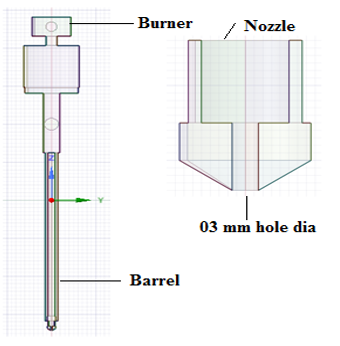
This boiler membrane design enables a larger coil tube to be used. This boiler runs on Light Diesel Oil (LDO), which is delivered by a gear pump with a 2000-liter-per-hour output capacity and a delivery pressure of 50 pounds per square inch. There is only one mesh type filter with an 80x80 mesh at the primary storage tank's outlet. The circulation burner design of the pressure jet burner prevents leakage and eliminates the risk of a fire. The nozzle has a diameter of 4 mm, allowing for optimum fuel automation.
2.1 Methodology of exergy analysis
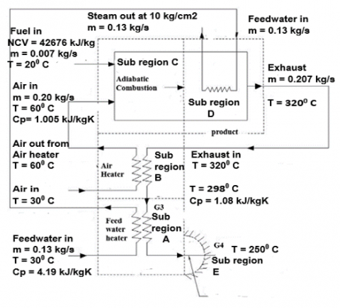
The exergy method is used to assess the exergy loss rate in the marine boiler to analyse the operation of the waste heat plant as shown in Figure 5. As indicated in Figure 5, the control region including this auxiliary boiler is divided into five regions. The feedwater heater is in A, the air heater is in B, the adiabatic combustion chamber is in C, the steam generator is in D, and the mixing chamber is in E. The following are the measures to take:
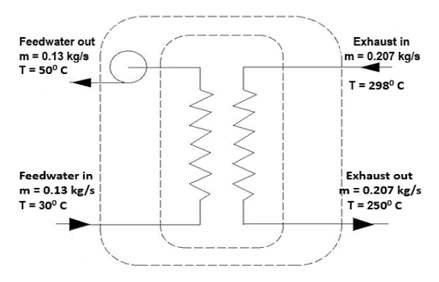
Figure 2. Mass and energy balance of feedwater heater
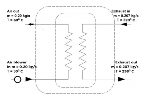
Figure 3. Mass and energy balance of air heater
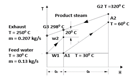
Figure 4. Enthalpy-temperature of auxiliary
Figure 5. Schematic diagram of Marine boiler
The exergy loss is calculated using the auxiliary boiler parameter and validated by computational fluid analysis of the burner nozzle. The mass and energy balance, as well as the exergy loss, are calculated using Eqns. (1)-(12). The thermodynamics' law was utilised to determine exergy based on the results from the auxiliary boiler experiment. Figures 2-5 depict the energy intake and loss of the stream in the system's sub-region.
3.1 Mass and energy balance of auxiliary boiler
3.1.1 Incoming stream to control volume
Sub-region A, feedwater heater:
${{\overset{.}{\mathop{\text{m}}}\,}_{\text{w}}}\text{x}{{\text{C}}_{\text{pw }}}\text{x}{{\text{T}}_{\text{w}}}$ (1)
Feedwater heater: 166 kW.
Subregion B, Air preheater:
${{\overset{.}{\mathop{\text{m}}}\,}_{\text{a}}}\text{x}{{\text{C}}_{\text{pa}}}\text{x}{{\text{T}}_{\text{a}}}$ (2)
Air preheater: 62 kW.
Subregion C, Fuel combustion at the furnace: mf x NCV.
Fuel combustion: 299 kW.
3.1.2 Outgoing stream to control volume
Sub region D, Steam generation:
${{\overset{.}{\mathop{\text{m}}}\,}_{\text{s}}}\text{x}{{\text{C}}_{\text{ps }}}\text{x}{{\text{T}}_{\text{s}}}$ (3)
Steam generation: 362 kW.
Sub region E, Exhaust gas out:
${{\overset{.}{\mathop{\text{m}}}\,}_{\text{g}}}\text{x}{{\text{C}}_{\text{pg }}}\text{x}{{\text{T}}_{\text{g}}}$ (4)
Exhaust gas: 113 kW.
3.1.3 Mass balance of Marine boiler
Incoming stream mass = outgoing stream mass.
${{\overset{.}{\mathop{\text{m}}}\,}_{\text{w}}}+{{\overset{.}{\mathop{\text{m}}}\,}_{\text{a}}}+{{\overset{.}{\mathop{\text{m}}}\,}_{\text{f}}}={{\overset{.}{\mathop{\text{m}}}\,}_{\text{s}}}+{{\overset{.}{\mathop{\text{m}}}\,}_{\text{g}}}$ (5)
0.337 kg/sec = 0.337 kg/sec.
3.1.4 Energy balance of Marine boiler
Incoming Stream Energy = outgoing Stream Energy.
Refer to Figure 4 and 5 and Eqns. (1)-(5).
527 kW = 475 kW + 52 kW (radiation loss).
3.2 Exergy balance of Marine boiler
3.2.1 Incoming stream to control volume
When displaying the process line in T-H coordinates, two oblique lines depict temperature changes for a feed, air heater, and steam generator heat exchanger with enthalpy rate, as shown in Figure 4. A schematic architecture of an experimental setup is shown in Figure 5. This auxiliary boiler's system is run by calculating the amount of work lost due to component processes and operational procedures. Convective, convective, and radiant heat transfer is used to transmit thermal energy between two streams in an air, feedwater heater, or steam generator. Refer to Eqns. (6)-(12).
$\Phi =1.0401+0.1728(h/c)$ (6)
Chemical exergy of the LDO ɸ = 4541.65 kJ / kg.
3.2.2 Exergy balance of sub-region A
${{\text{I}}_{\text{A}}}=\left( {{\text{E}}_{\text{G}3}}-{{\text{E}}_{\text{G}4}} \right)-\left( \text{E}{{\text{W}}_{2-}}{{\text{E}}_{\text{W}1}} \right)$ (7)
Exergy balance of sub-region A, IA = 1.12 kJ.
3.2.3 Exergy balance of sub-region B
${{\text{I}}_{\text{B}}}=\left( {{\text{E}}_{\text{G2}}}-{{\text{E}}_{\text{G3}}} \right)-\left( {{\text{E}}_{\text{A}2-}}{{\text{E}}_{\text{A}1}} \right)$ (8)
Exergy balance of sub region B, IB = 2.78 kJ.
3.2.4 Irreversibility of the combustion process sub-region C
${{\text{I}}_{\text{C}}}={{\text{E}}_{\text{F}2}}+{{\text{E}}_{\text{A}2}}-{{\text{E}}_{\text{G}1}}$ (9)
Ic = 35024 kJ.
3.2.5 Exergy balance of sub-region D
${{\text{I}}_{\text{D}}}=\left( {{\text{E}}_{\text{G1}}}-{{\text{E}}_{\text{G2}}} \right)-\left( {{\text{E}}_{\text{S}2-}}{{\text{E}}_{\text{S}1}} \right)$ (10)
ID = 11067 kJ.
3.2.6 Exergy balance of sub-region E
${{\text{I}}_{\text{E}}}={{\text{E}}_{\text{G}4}}$ (11)
IE = 576 kJ.
3.2.7 Rational efficiency of the plant
$\Psi ={{\text{E}}_{\text{s}2}}/{{\text{E}}_{\text{f}2}}$ (12)
Ψ = 0.022 = 2.25%.
3.3 Computational fluid analysis of burner nozzle
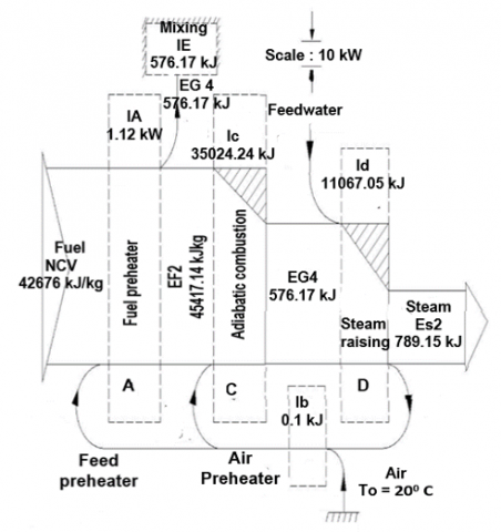
Figure 6. Grossman diagram of marine boiler
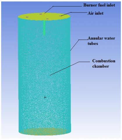
Figure 7. Meshing of the burner
The Ansys 13.2 code is used to do numerical calculations on the pressure jet burner. The Ansys 13.2 programming environment utilised in this study provides an interface to external fuel atomization simulations that streamlines nozzle flow with built-in atmospheric conditions, optimum solver settings, and pertinent input and output parameters. Modelling the mixing processes and blending of air and fuel mixtures is easier with Ansys fluid mixing simulation. To try to predict injector nozzle optimization, the model employs two partial differential equations for two variables, k-w, with the first variable being the turbulent kinetic energy (k) for fuel and the second (w) being the particular rate of heat dissipation. This software Ansys 13.2 solves the Navier-Stokes equations in dynamic form. The effect of atomization of fluid flow over the burner nozzles illustrated in Figures 7-13 is studied using the conventional k–w turbulence model. In this K-omega model, the standard model with the two-step reaction is used for the atomization analysis. The X-Y plane geometry of a boiler burner with nozzle diameter R = 0.3 mm is used for validation with experimental results. Refer to Figures 8-9 and Table 3.
Figure 8. Meshing of the burner
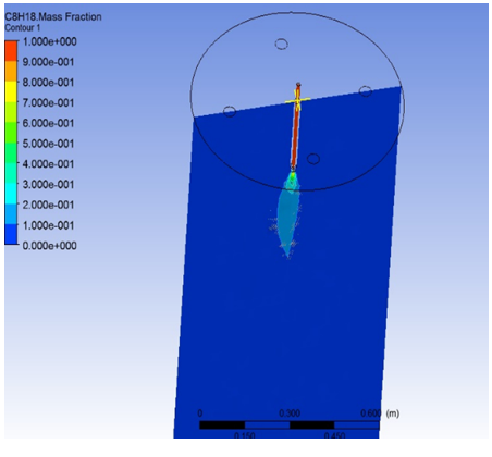
Figure 9. Mass fraction contour in YZ plane
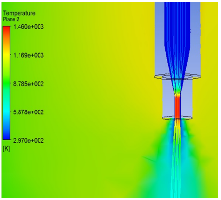
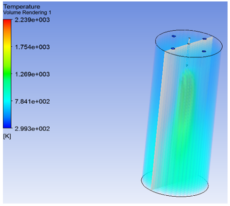
Figure 10. Temperature plane of fuel of burner
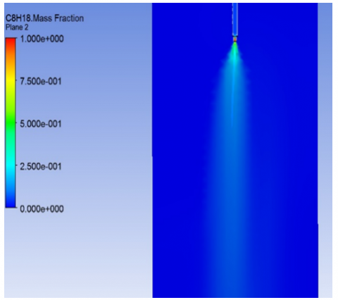
Figure 11. Mass fraction plane of the fuel flow of burner
Figure 12. Atomization of fuel in the X-Y plane of a burner
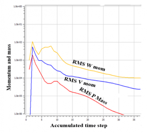
Figure 13. Variation of momentum and mass
3.4 Jet burner meshing and grid independence test
Pressure jet burner meshing is carried out with Tetrahedrons. Single Step reaction model is used for the solver as per Figures 7 and 8. The grid becomes independent above the grid size of 3279045, hence this grid size is chosen for the current study to achieve computational economy.
The meshing cardinals are as follows (Table 3).
Table 3. The meshing of the burner nozzle
|
Sr no. |
Cardinals |
No. of elements |
|
1 |
Number of Tetrahedrons |
3279045 |
|
2 |
Total Number of Faces |
359089 |
|
3 |
Total Number of Elements |
3279056 |
|
4 |
Total Number of Nodes |
645815 |
3.5 Validation of CFD results with experimental results
Auxiliary boiler data is also validated by distributing a questionnaire to onboard intern cadets and collecting data via a Google form. The combustion chamber has a larger exergy loss (35024 kJ) and is well atomized, according to a computational model of a pressure jet burner with a diameter of 3 mm. The burner is operating at maximum capacity when the nozzle diameter is 3 mm. The partial oxidation of CO2 in the burner's nozzle is depicted in Figure 9. As seen in Figure 10, the combustion product's temperature contour demonstrates that it is concentrated in the combustion chamber's centre. Figure 11 shows the distribution of the mass fraction of C8H18 diesel fuel at the burner nozzle's tip. The mass fraction of fuel and the atomization process is represented in Figure 12. Figure 13 shows the turbulence of different transport species as a function of a time step. The exergy loss in the combustion chamber exceeds 35024 kJ, and numerical analysis of a pressure jet burner with a diameter of 3 mm shows good atomization. It shows that the burner is working in full capacity with a 3 mm diameter nozzle. The higher exergy is due to high heat generation and subsequent unburn after the light diesel oil is burned.
3.6 Findings of exergy analysis
Figure 6 (Grossman diagram) is a flowchart of the available work as it progresses through system components. The magnitude of the useful work and exergy losses in the components are visually shown by the relative width of the workflow lines. The highest exergy loss occurs in the combustion chamber, as seen in this exergy flow diagram. The exergy approach has a substantial impact on where and how huge inefficiencies occur in the energy system, as seen in the Grossman diagram of a naval boiler. The accurate distribution of losses in the air, water, and fuel streams is presented, with the erroneous data provided by the energy-balance approach removed. The quantitative values of the individual losses that make up the total component loss are shown in Table 2. The combustion chamber in sub-region C has the highest exergy loss of 35024 kW, as shown in Figure 6, which will be relevant in the discussion about energy-saving strategies based on exergy analysis. Figures 9 to 11 represents the mass fraction contour and temperature plane in the nozzle region. Figure 12 shows the fuel automation in the X-Y plane. At a nozzle diameter of 3 mm, fuel atomization is maximum. Figure 13 shows a momentum and mass variable with a time step. The study uses the auxiliary boiler to calculate the first and second laws of thermodynamic efficiency, exergy efficiency, and numerical analysis to find the most efficient technique of increasing available energy.
This study was conducted on an auxiliary boiler to determine the thermal performance indicator with various components irreversibility, and the following conclusions were reached:
|
Symbol |
|
|
ṁa |
The mass flow rate of air (kg/s) |
|
da |
Diameter of fuel burner jet (m) |
|
t |
Time (s) |
|
T |
Temperature (K) |
|
Cps |
Specific heat of steam (kJ/kg) |
|
Cw |
Specific heat of water (kJ/kg) |
|
ṁ w |
The mass flow rate of water (kg/s) |
|
ṁ f |
The mass flow rate of fuel (kg/s) |
|
ṁ g |
The mass flow rate of gas (kg/s) |
|
Greek symbols |
|
|
ɸ |
Chemical exergy |
|
Ψ |
Rational efficiency |
|
Subscription |
|
|
stoic |
Stoichiometric |
|
act |
Actual |
|
i |
Initial |
|
- |
Average |
|
a |
Analytical |
[1] Tsatsaronis, G. (2007). Definitions and nomenclature in exergy analysis and exergoeconomics. Energy, 32(4): 249-253. https://doi.org/10.1016/j.energy.2006.07.002
[2] Som, S.K., Datta, A. (2008). Thermodynamic irreversibilities and exergy balance in combustion processes. Progress in Energy and Combustion Science, 34(3): 351-376. https://doi.org/10.1016/j.pecs.2007.09.001
[3] Aljundi, I.H. (2009). Energy and exergy analysis of a steam power plant in Jordan. Applied Thermal Engineering, 29(2-3): 324-328. https://doi.org/10.1016/j.applthermaleng.2008.02.029
[4] Saidur, R., Ahamed, J.U., Masjuki, H.H. (2010). Energy, exergy and economic analysis of industrial boilers. Energy Policy, 38(5): 2188-2197. https://doi.org/10.1016/j.enpol.2009.11.087
[5] Budnik, M., Stanek, W. (2011). Exergetic cost of steam power plant operation. Archives of Thermodynamics, 32(2): 39-54. https://doi.org/10.2478/v10173-011-0008-2
[6] Hajidavalloo, E., Vosough, A. (2011). Energy and exergy analyses of a supercritical power plant. International Journal of Exergy, 9(4): 435-452. https://doi.org/10.1504/IJEX.2011.044059
[7] Ohijeagbon, I.O., Waheed, M.A., Jekayinfa, S.O. (2015). Methodology for Energy and Energy Analysis of Steam Boilers. Methodology, 5(1): 28-47.
[8] Taillon, J., Blanchard, R.E. (2015). Exergy efficiency graphs for thermal power plants. Energy, 88: 57-66. https://doi.org/10.1016/j.energy.2015.03.055
[9] Abdulrahman, R.S., Ibrahim, F.A., Faisel, S.H. (2020). Numerical study of heat transfer and exergy analysis of shell and double tube heat exchanger. International Journal of Heat and Technology, 38(4): 925-932. https://doi.org/10.18280/ijht.380419
[10] Gulotta, T.M., Guarino, F., Mistretta, M., Cellura, M., Lorenzini, G. (2018). Introducing exergy analysis in life cycle assessment: A case study. Mathematical Modelling of Engineering Problems, 5(3): 139-145. https://doi.org/10.18280/mmep.050302
[11] Enebe, K.O., Odukwe, A.O. (2018). Evaluation of energy and exergy efficiency of steam generation and utilization in nigerian pharmaceutical industries. Journal of Energy Technologies and Policy, 8(3): 37-46.
[12] Ahmadi, M.H., Alhuyi Nazari, M., Sadeghzadeh, M., Pourfayaz, F., Ghazvini, M., Ming, T., Sharifpur, M. (2019). Thermodynamic and economic analysis of performance evaluation of all the thermal power plants: A review. Energy Science & Engineering, 7(1): 30-65. https://doi.org/10.1002/ese3.223
[13] Jouhara, H., Khordehgah, N., Almahmoud, S., Delpech, B., Chauhan, A., Tassou, S.A. (2018). Waste heat recovery technologies and applications. Thermal Science and Engineering Progress, 6: 268-289. https://doi.org/10.1016/j.tsep.2018.04.017
[14] Pal, J.S., Sapali, S.N., Anil, T.R. (2019). Exergy analysis and irreversibility of combustion process of an auxiliary boiler for marine application. In Renewable Energy and Its Innovative Technologies, 61-68. https://doi.org/10.1007/978-981-13-2116-0_6
[15] Pal, J.S., Sapali, S.N., Anil, T.R. (2019). Exergy analysis of auxiliary boiler for marine application. In Proceedings of the Fourth International Conference in Ocean Engineering (ICOE2018), pp. 1057-1071. https://doi.org/10.1007/978-981-13-3119-0_73
[16] Pal, J.S., Sapali, S.N., Anil, T.R., Shinde, A.S. (2021). Exergy analysis of a plate type freshwater generator used in marine vessels. International Review of Mechanical Engineering (I.RE.M.E.), 15(8): 434. https://doi.org/10.15866/ireme.v15i8.21332
[17] Nikam, K.C., Kumar, R., Jilte, R. (2021). Exergy and exergo-environmental analysis of a 660 MW supercritical coal-fired power plant. Journal of Thermal Analysis and Calorimetry, 145(3): 1005-1018. https://doi.org/10.1007/s10973-020-10268-y
[18] Khaleel, O.J., Ibrahim, T.K., Ismail, F.B., Al-Sammarraie, A.T. (2021). Developing an analytical model to predict the energy and exergy based performances of a coal-fired thermal power plant. Case Studies in Thermal Engineering, 28: 101519. https://doi.org/10.1016/j.csite.2021.101519
[19] Badiger, S., Katti, V.V., Tumkur, A.R. (2020). Heat transfer characteristics of a coaxial inverse diffusion flame jet impingement with an induced swirl. International Journal of Heat and Technology, 38(4): 887-894. https://doi.org/10.18280/ijht.380415
[20] Tarla, M.R., Surapaneni, S.R., Varughese, K.T. (2021). Modifications of sub-components in thermal power plants for exergetic efficiency. International Journal of Heat and Technology, 39(2): 573-580. https://doi.org/10.18280/ijht.390227
[21] Ahern, J.E. (1980). Exergy Method of Energy Systems Analysis. John Wiley & Sons, New York, 102-114.
[22] Moran, M.J. (1982). Availability analysis: A guide to efficient energy use. Prentice-Hall, Englewood Cliffs, New Jersy, 44-65.
[23] Kotas, T.J. (2013). The exergy method of thermal plant analysis. Exergon Publishing Company, UK, London, 72-98.