Brahim Rostane* | Said Abboudi
© 2022 IIETA. This article is published by IIETA and is licensed under the CC BY 4.0 license (http://creativecommons.org/licenses/by/4.0/).
OPEN ACCESS
In this study, the forced convection of a stationary laminar flow over two heated wall-mounted perforated cubes are presented. These two cubes are placed in a tandem arrangement on a flat plate. The equations of continuity, momentum and energy are solved using the finite volume method based on the Rhie and Chow method for velocity-pressure coupling. The influence of the perforation volume of the cubes is studied and compared with the case of obstacles without holes for a constant heat flux subjected to the solid part. The results of mean Nusselt number and drag coefficients are presented at the levels of the two obstacles and the plane plate for different Reynolds numbers and different distances between them. The results showed that the insertion of holes in the cubes improves heat transfer from the diameter D/H=0.62, and this transfer rises with increasing diameter of the perforation of the cubes. The results showed also a decrease in the drag coefficient for the first obstacle with rising volume of the perforation.
convective heat transfer, laminar flow, obstacle with hole, surface-mounted cubes, tandem
The flow around obstacles represents a major axis of research that touch the domains of fluid mechanics and heat transfer as these obstacles create vortex zones in the surroundings, which implies an increase in thermal performance and therefore the efficiency in various application fields such as flat plate solar collectors and heat exchangers.
Several numerical and experimental studies have been carried out for the three-dimensional flow around a surface-mounted bluff body for different flow regimes and with different shapes and orientations of obstacles [1-11]. The researchers visualized several types of generated vortices by the separation of the boundary layer, in particular; the horseshoe vortex, side vortices, vortex on top of obstacles, arc-shaped vortex, hairpin vortices in downstream wake regions of the bluff body, the recirculation zone, the saddle and reattachment points as well as studying the influences of the vortex shedding on it.
Meinders and Hanjalić [12] conducted an experimental investigation of heat transfer in a turbulent flow around two cubes surface mounted in a channel, using the Laser Dopler Anenometry, Oil-film visualization and Infrared Thermography. The results showed that the distribution of the heat transfer coefficient is a function of the dynamic field of the flow and this distribution is symmetrical for the tandem arrangement. On the other hand, for the staggered arrangement, it is asymmetrical.
A three-dimensional numerical study of a laminar flow around two cubes mounted in a tandem and staggered arrangements for a Reynolds number varying between 100 and 500 was presented by Eslami et al. [13]. Discussion was made based on the results of vortex structures, separation and reattachment points. The authors showed that the presence of the second cube modifies the flow field and the vortex structures compared to the case of a single cube. Hence, in the tandem arrangement, when the distance between the two cubes is fewer than 3, 5H (H: is the height of the cube), a single horseshoe vortex wraps around the two cubes. On the other hand, beyond this distance, two separate horseshoe vortices are formed and the wake behind the first cube is separated from the second.
Nakajima et al. [14] performed numerical simulations of laminar flow in a channel around rectangular obstacles using 3 rows with a staggered arrangement for a Reynolds number varying between 100 and 500. The results revealed that the heat transfer varies with the Reynolds number at the diverse lateral surfaces of the blocks. Thus, the heat transfer is affected by the flow structures and the temperature field around the blocks of the third row and it is different from the first and second rows. The laminar flow around two obstacles placed in tandem and staggered positions with different distances for the two arrangements was analyzed by Mousazadeh et al. [15]. This study was carried out for a Reynolds number varying between 150 and 300 using the Open FOAM code using the finite volume method. The authors revealed that the drag coefficient in staggered arrangement is greater than in tandem and the heat transfer around the second cube is less than the first cube. Moreover, with the increase of the distance in the streamwise direction, the average Nusselt number (Nu) of the second cube becomes the same as that of the first cube. Karwa et al. [16, 17] conducted an experimental study in a rectangular channel with smooth, perforated and half-perforated baffles. The results demonstrated that the highest values of the Nusselt number concern solid baffles and half-perforated baffles. Coefficients of friction for fully perforated baffles are the lowest. So, baffles with the largest perforation diameter give the best performance. In the same context, some researchers [18-28] have examined the orientation, shape and position of perforated baffles in rectangular or circular channels by improving thermal and dynamic performance in solar collectors and heat exchangers.
Salem et al. [29] made an experimental study in order to investigate the behavior of the fluid flow and the heat transfer in the annular space of the heat exchangers that are provided with perforated single segment baffles (SSPBs). They sought to compare the efficiency of the perforated and non-perforated baffles and the different geometries of SSPBs at different water flow rates and inlet temperatures for a Reynolds number varying between 1,380 and 5,700. The results revealed that the mean Nusselt number of the ring rises with increasing SSPBs hole spacing ratio and the angle of two inclination. Additionally, the authors provided new correlations for heat transfer and pressure drops. Kok et al. [30] explored experimentally and numerically the fluid flow with a coaxial jet around the perforated obstacles in order to control the behavior of the thermal mixture. A test bench was built to do several tests that were numerically simulated using the LES turbulence model. The results showed that the perforated obstacles improve the performance of the mixture especially for obstacles with high permeability. In another line of research, Esfe et al. [31] implemented a numerical study of the forced convection of nanofluids around two obstacles in a channel using three thermophysical models and their effect on the Nusselt number. They found that the Nusselt number increases with increasing concentration of nanofluids, decreasing Richardson number as well as decreasing height or width of obstacles. In the same field, some studies [32-36] have been reported on the heat transfer by convection with nanofluids using different forms of obstacles and channels.
Benzennin et al. [37] investigated the convective laminar flow in a channel around a single obstacle with different perforation volumes using the FLUENT code. Their results showed that the use of perforated baffles improves heat transfer by 0.03% to 14.52%. Rostane et al. [38] analyzed numerically the turbulent fluid flow around a wall-mounted perforated cube. The study was carried out for several diameters for a Reynolds number of 105. The study focused on the change in the dynamic behavior of the flow with different diameters of the holes inserted by studying the streamlines particularly the recirculation zone downstream of the obstacle. The results showed that increasing the perforation diameter resulted in the increase of the number of vortices downstream of the bluff body.
In view of the above cited studies, the present research is conducted with the aim to combine all the works forementioned. The contribution is therefore to carry out a numerical study of the convective laminar of three-dimensional flow around two wall-mounted perforated cubes with a tandem arrangement, in order to analyze the heat transfer, the vortex structures and the relationship between them. This study intends to assess the impact of inserting holes in these obstacles on the performance of heat transfer.
2.1 Geometry and computational domain
The geometry of this study is summarized in two perforated or solid cubes of height H, with different diameters of holes: D/H=0.32, 0.42, 0.62, 0.73, 0.88, placed in tandem position on a flat plate at the distance 3H at the inlet and 8H at the outlet. The equivalent diameter corresponding to D/H is calculated as follows: for D/H=0.32, D=0.32H=0.8cm when H=2.5cm. The dimensions of the studied system are shown in Figure 1. The height and the width of the computation domain are respectively 6H and 10H. The distance between the 2 cubes is equal to L which varies according to the case studied.
Figure 1. Geometry of the configuration with the various obstacles
2.2 Mathematical model
In this study, the continuity (Eq. (1)), momentum (Eq. (2)) and energy (Eq. (3)) equations are used for three-dimensional steady state, laminar and incompressible flow:
$\frac{\partial u_{i}^{+}}{\partial x_{i}^{+}}=0, i=1,2,3$ (1)
$u_{j}^{+} \frac{\partial u_{i}^{+}}{\partial x_{i}^{+}}=\frac{\partial p^{+}}{\partial x_{i}^{+}}+\frac{1}{R e} \frac{\partial^{2} u_{i}^{+}}{\partial x_{i}^{+^{2}}}, i, j=1,2,3$ (2)
$u_{j}^{+} \frac{\partial T_{i}^{+}}{\partial x_{i}^{+}}=\frac{1}{\operatorname{Re} \cdot \operatorname{Pr}} \frac{\partial^{2} T_{i}^{+}}{\partial x_{i}^{+^{2}}}, i, j=1,2,3$ (3)
The dimensionless variables used in the previous equations are:
$u_{i}^{+}=\frac{u_{i}}{U_{i n}}, u_{j}^{+}=\frac{u_{j}}{U_{i n}} x^{+}=\frac{x}{H}, p^{+}=\frac{p}{\rho U_{i n}^{2}}, T^{+}=\frac{T-T_{i n}}{\frac{q_{w} h}{\lambda}}$
With Uin, Tin are respectively the average of axial velocity and the temperature at the inlet.
2.3 Boundary conditions and numerical model
For the boundary conditions at the inlet of the computation domain, the velocity and the temperature are uniform. The axial velocity is chosen according to the Reynolds number varying from 150 to 300 and Pr=0.7. At the outlet, atmospheric pressure was imposed. No-slip condition is assumed on the wall surfaces (the flat plate and obstacles) that are heated under a uniform heat flux. The symmetry condition has been employed in both side faces of the domain and the free flow condition is applied on the upper plane. The hexahedral structured with O-grid meshes is employed to solve the previously cited equations. This structure has been refined close to the solid walls.
The equations of continuity, momentum and energy are solved using the finite volume method with the code ANSYS CFX. To solve the convection terms, the second order Upwind scheme is utilized. The method of Rhie and Chow [39] is employed for the pressure-velocity coupling.
3.1 Grid independency study
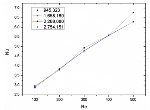
In any numerical study, the precision of the sought-after solution strongly depends on the quantity of the mesh. Therefore, mesh sensitivity tests are essential to guarantee a solution independently of the chosen calculation grid. In the present study, for hexahedral meshes of 945,323, 1,658,160, 2,268,080 and 2,754,151 cells are tested with respect to the mean values of the Nusselt numbers (Figure 2). These grids have distances of 0.00929H, 0.00391H, 0.000821H and 0.000821H respectively between the first nodes and the solid walls. The study shows that the grids of 1,658,160, 2,268,080 and 2,754,151elements have similar results. Therefore, the grid of 1,658,160 cells offers the best compromise between precision and calculation time.
Figure 2. Mesh sensitivity test
3.2 Code validation
For validation, the results of the present study are compared with those found by Nakajima et al. [14] and Moussadak et al. [15], for the variation of the mean Nusselt number as a function of the Reynolds number, for a distance between obstacles of L/H=4.5 and assuming that the flat plate is adiabatic. The results found showed a good agreement between them (Figure 3).
Figure 3. Mean Nusselt comparison chart between the present study and those of Nakajima et al. [14] and Mousazadeh et al. [15] for different Reynolds number with a distance between the two cubes: L=4.5H
3.3 Variation of mean Nusselt number
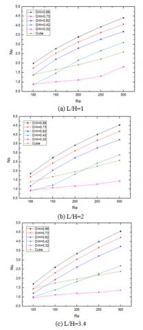
For all cases of distances between obstacles (L/H=1, 2 and 3.4), comparison of different results of the mean Nusselt number (Nu) as a function of the Reynolds number was carried out for the different configurations and obstacles with or without holes (D/H=0.32, 0.42, 0.62, 0.73, 0.88) (Figure 5). It was found from these figures that the Nusselt number increases with the increase in the diameter of the holes and also with increasing Reynolds number.
By comparing the case of the obstacles without holes with the other cases and for the case L/H=1, the values of Nu for the cube as a function of Re are the same by comparing them with the values for the obstacle with diameter D/H=0.32, while for the distance L/H=2, the values are greater than the latter. Finally, for the case L/H=3.4, the values are almost identical to the case of an obstacle with diameter D/H 0.62 (Figure 5). In order to display more details about these results, the mean Nusselt number curves have been shown for obstacles 1 and 2 (Figures 6 and 7). Regarding obstacle1, the results are practically the same whatever the distance between the two obstacles (Figure 6), namely that the values of Nusselts are greater in the case of obstacle with hole of diameter D/H=0.88 and the cube has smaller values regardless of the Reynolds number. Here, the values of the mean Nusselts numbers decrease with decreasing in the diameters of the holes and it can be explained as follows in Figures 8(c), (d) up to 13(c), (d), it is observed that the perforated obstacles create the flow inside the perforation. Therefore, the heat transfer enhances compared to the solid obstacle. In the axial velocity contours figures, the velocity is greater for large diameter perforations which increases the convective transfer coefficient.
At the obstacle 2, it is found that the heat transfer is less intense than in the obstacle 1 (Figure 7) and this can also be seen on the temperature contours (Figures 8(a) to 13(a)) where it is greater at the second obstacle. This is because the dynamic field is less intense due to the position of the first obstacle (obstacle 1 protects obstacle 2 from axial flow). This position also creates a recirculation zone downstream of the obstacle 1 (Figures 8(d) to 13(d)) which decreases the velocity in the surroundings and maintains the temperature at the level of the wall.
Figure 4. Streamlines on the flat plate For Re=250
Figure 5. Mean Nusselt number on solid walls for different distances
Figure 6. Number of Nu on obtacle1 for different distances and perforation diameters
Figure 7. Number of Nu on obtacle2 for different distances and perforation diameters
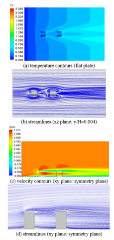
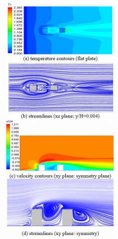
Figure 8. Streamlines, temperature and velocity contours around obstacles for the case D/H=0.92, L=2H, Re=300
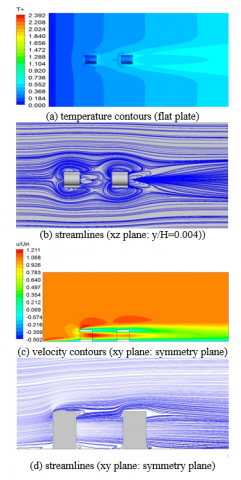
Figure 9. Streamlines, temperature and velocity contours around obstacles for the case D/H=0.73, L=2H, Re=300
Figure 10. Streamlines, temperature and velocity contours around obstacles for the case D/H=0.62, L=2H, Re=300
In addition, Figure 7 shows that the curves of the average Nusselt number at the obstacle 2 are almost the same when comparing them to the curves of the obstacle 1, namely that Nu increases with the increase in the perforation diameter except for the cube where the values are greater than the D/H=0.32 diameter case regardless of the number of Reynolds and in the case of diameter D/H=0.42 for Re values below 200. This finding can be explained as follows in Figures 8(d) up to 13(d), from the diameter D/H=0.42 and for Re=300, there is a continuous flow which crosses the two obstacles through the perforations. This jet cuts the recirculation zone in half, one above the jet and the other below. This flow through the perforations promotes heat transfer and therefore the Nusselt number increases. For the diameter D/H=0.32, it was found that the jet does not reach the obstacle 2 (Figure 12(c), (d)) because the low flow rate that comes out of the perforation of the obstacle 1 (small diameter) will allow the stagnation of the fluid in the perforation of obstacle 2. It implies, consequently, a large increase in the temperature at the level of the wall of the hole (Figure 12(a)).
At the flat plate, Figures from 8(a) to 13(a) illustrate that the dimensionless temperature is greater at the wake level at the sides and downstream of the obstacles, especially the obstacle 2 which implies a reduction in heat transfer at these places due to the presence of counter-rotating vortices and recirculation areas where the dynamic field is weak. In these figures, it can also be noted that the temperature decreases upstream of obstacle 1 precisely in the horseshoe vortex. This reduction is greater for the solid obstacle (greater vortex volume) and less important with the increase in the volume of the holes (less important vortex volume). Figure 11(a), (case (D/H=0.42)) depicts that the thermal field is more important than that of the other cases due to the appearance of two additional counter-rotating vortices (Figure 11(b)) that will widen the recirculation zone (Figure 11(d)) and moving the reattachment point away from obstacle 2.
Regarding the streamlines (Figure 4), there is the appearance of several vortices due to the presence of obstacles in the flow. These vortices consist of a horseshoe vortex (A), vortices in the proximity of the side surfaces (B) and hairpin vortices in the wake region downstream cubes (C). Furthermore, there is the presence of a line of symmetry for the downstream wake region of each cube, separation (D) and reattachment points (E). The figures show an overlap of the vortex regions of each cube with respect to the other, which decreases when the distance between the two cubes increases. Thus, for the space L/H=1 (Figure 4(a)), the horseshoe vortex region of the first cube (obstacle1) is also wrapped around the second. However, for the space L/H=3.5 (Figure 4(b)), the independent horseshoe vortex appears only partially around the second cube (obstacle2). The figures of this study and those of Moussadak et al. [15] are almost identical.
Figure 11. Streamlines, temperature and velocity contours around obstacles for the case D/H=0.42, L=2H, Re=300
Figure 12. Streamlines, temperature and velocity contours around obstacles for the case D/H=0.32, L=2H, Re=300
Figure 13. Streamlines, temperature and velocity contours around obstacles for the for the cube case, L= 2H, Re=300
3.4 Drag coefficients
For fluid flow around bluff bodies, the study of the resistance is essential. Therefore, the drag coefficient was calculated for both obstacles.
Figures 14 and 15 give the drag coefficients at both obstacles for the different cases studied and also for different distances. For obstacle 1, the drag coefficient increases with the decrease in the hole diameter. Thus, the solid obstacle has the greatest one. This can be explained by studying the streamlines on the xz and xy planes (Figures 8(b), (d) up to 13(b), (d)). On the xz plane (y/H=0.004), the span of the horseshoe vortex region wrapped around the obstacle 1 is greater in the case without a hole and decreases with the increase of the perforation diameters which generates a decrease in the drag coefficient of the cases of obstacles with holes. With regard to obstacle 2, there is an opposite effect. The area of the horseshoe vortex region wrapped around the obstacle1 is smaller for the no-hole case. This area grows with growing diameter of the holes. Hence, the drag coefficient increases for large obstacles diameters. On the xy symmetry plane and for the obstacle1, the recirculation zone downstream of the obstacle is greater for the cases without hole and D/H=0.34. From the case D/H=0.42, it is observed two zones of separation and reattachment of the fluid or two vortex zones. One of them is located above the jet and the other below. The thickness of these zones reduces with the rise in the perforation diameter. Therefore, it will reduce the drag coefficient. For obstacle 2, the opposite is observed. The drag coefficient rises with rising diameter of the holes (Figure 15) and this because the fluid impact the force against the obstacle 2. This force increases with increasing the flow rate of the jet coming out of the hole of obstacle 1. For the case D/H=0.32 (Figure 12), the jet does not manage to reach obstacle 2. Consequently, the drag coefficient is the smallest compared to the other cases of obstacles with holes.
Figure 14. Drag coefficient on obstacle1 for different hole diameters
Figure 15. Drag coefficient on obstacle2 for different hole diameters
In this study, the forced convection of a stationary laminar flow over two heated wall-mounted perforated cubes is presented. These two obstacles are placed in a tandem arrangement on a flat plate. The influence of five cases of perforation of cubes is studied and compared to the case of obstacles without holes for a constant flow for the whole solid part. Several vortices have been appeared due to the presence of obstacles in the flow of a horseshoe vortex; vortices in the proximity of the side surfaces, hairpin vortices in the wake region downstream cubes, with the vortex regions of each cube overlapping with respect to the other, and recirculation zones behind the two obstacles. With the increase in the diameter of perforations and the Reynolds number and decreasing space between the obstacles, there occurs an appearance of two zones of separation and reattachment of the fluid or two recirculation zones behind the obstacles. One of them is located above the jet and the other below. These zones decrease with increasing perforation volumes. There is an improvement in heat transfer in the system with rising diameter of the cubes holes compared to solid obstacles except for small diameters.
The study revealed also a decrease in the drag coefficient for the first obstacle with a growth in the volume of the perforation. On the other hand, there is an opposite effect for the second.
[1] Martinuzzi, R.J., Tropea, C. (1993). The flow around a surface-mounted prismatic obstacle placed in a fully developed channel flow. Journal of Fluids Engineering, 115(1): 85-92. https://doi.org/10.1115/1.2910118
[2] Hussein, H.J.A., Martinuzzi, R.J. (1996). Energy balance for turbulent flow around a surface mounted cube placed in a channel. Physics of Fluids, 8(3): 764-780. https://doi.org/10.1063/1.868860
[3] Rodi, W. (1997). Comparison of LES and RANS calculations of the flow around bluff bodies. Journal of Wind Engineering and Industrial Aerodynamics, 69: 55-75. https://doi.org/10.1016/S0167-6105(97)00147-5
[4] Krajnovic, S., Davidson, L. (2002). Large-eddy simulation of the flow around a bluff body. AIAA Journal, 40(5): 927-936. https://doi.org/10.2514/2.1729
[5] Becker, S., Lienhart, H., Durst, F. (2002). Flow around three-dimensional obstacles in boundary layers. Journal of Wind Engineering and Industrial Aerodynamics, 90(4-5): 265-279. https://doi.org/10.1016/S0167-6105(01)00209-4
[6] Nakamura, H., Igarashi, T., Tsutsui, T. (2003). Local heat transfer around a wall-mounted cube at 45 to flow in a turbulent boundary layer. International Journal of Heat and Fluid Flow, 24(6): 807-815. https://doi.org/10.1016/j.jweia.2007.06.009
[7] AbuOmar, M.M., Martinuzzi, R.J. (2008). Vortical structures around a surface-mounted pyramid in a thin boundary layer. Journal of Wind Engineering and Industrial Aerodynamics, 96(6-7): 769-778. https://doi.org/10.1016/j.jweia.2007.06.009
[8] Lim, H.C., Ohba, M. (2014). Interference effects of three consecutive wall-mounted cubes placed in deep turbulent boundary layer. Journal of Fluid Mechanics, 756: 165-190. https://doi.org/10.1017/jfm.2014.454
[9] McClean, J.F., Sumner, D. (2014). An experimental investigation of aspect ratio and incidence angle effects for the flow around surface-mounted finite-height square prisms. Journal of Fluids Engineering, 136(8): 081206. https://doi.org/10.1115/1.4027138
[10] Leite, H.F., Avelar, A.C., Abreu, L.D., Schuch, D., Cavalieri, A. (2018). Proper orthogonal decomposition and spectral analysis of a wall-mounted square cylinder wake. Journal of Aerospace Technology and Management, 10. https://doi.org/10.5028/jatm.v10.867
[11] Gildersleeve, S., Amitay, M. (2020). Vortex dynamics of a low aspect ratio cantilevered cylinder immersed in a boundary layer. Journal of Fluid Mechanics, 901(A18). https://doi.org/10.1017/jfm.2020.555
[12] Meinders, E.R., Hanjalić, K. (2002). Experimental study of the convective heat transfer from in-line and staggered configurations of two wall-mounted cubes. International Journal of Heat and Mass Transfer, 45(3): 465-482. https://doi.org/10.1016/S0017-9310(01)00180-6
[13] Eslami, M., Tavakol, M.M., Goshtasbirad, E. (2010). Laminar fluid flow around two wall-mounted cubes of arbitrary configuration. Proceedings of the Institution of Mechanical Engineers, Part C: Journal of Mechanical Engineering Science, 224(11): 2396-2407. https://doi.org/10.1243/09544062JMES2026
[14] Nakajima, M., Yanaoka, H., Yoshikawa, H., Ota, T. (2005). Numerical simulation of three-dimensional separated flow and heat transfer around staggered surface-mounted rectangular blocks in a channel. Numerical Heat Transfer, Part A: Applications, 47(7): 691-708. https://doi.org/10.1080/10407780590911558
[15] Mousazadeh, S.M., Shahmardan, M.M., Tavangar, T., Hosseinzadeh, K., Ganji, D.D. (2018). Numerical investigation on convective heat transfer over two heated wall-mounted cubes in tandem and staggered arrangement. Theoretical and Applied Mechanics Letters, 8(3): 171-183. https://doi.org/10.1016/j.taml.2018.03.005
[16] Karwa, R., Maheshwari, B.K., Karwa, N. (2005). Experimental study of heat transfer enhancement in an asymmetrically heated rectangular duct with perforated baffles. International Communications in Heat and Mass Transfer, 32(1-2): 275-284. https://doi.org/10.1016/j.icheatmasstransfer.2004.10.002
[17] Karwa, R., Maheshwari, B.K. (2009). Heat transfer and friction in an asymmetrically heated rectangular duct with half and fully perforated baffles at different pitches. International Communications in Heat and Mass Transfer, 36(3): 264-268. https://doi.org/10.1016/j.icheatmasstransfer.2008.11.005
[18] Chamoli, S., Lu, R., Xie, J., Yu, P. (2018). Numerical study on flow structure and heat transfer in a circular tube integrated with novel anchor shaped inserts. Applied Thermal Engineering, 135: 304-324. https://doi.org/10.1016/j.applthermaleng.2018.02.052.
[19] El Habet, M.A., Ahmed, S.A., Saleh, M.A. (2022). The effect of using staggered and partially tilted perforated baffles on heat transfer and flow characteristics in a rectangular channel. International Journal of Thermal Sciences, 174: 107422. https://doi.org/10.1016/j.ijthermalsci.2021.107422
[20] Liu, C., Teng, J., Chu, J.C., Chiu, Y., Huang, S., Jin, S., Dang, T., Greif, R., Pan, H.H. (2011). Experimental investigations on liquid flow and heat transfer in rectangular microchannel with longitudinal vortex generators. International Journal of Heat and Mass Transfer, 54(13-14): 3069-3080. https://doi.org/10.1016/j.ijheatmasstransfer.2011.02.030
[21] Faujdar, S., Agrawal, M. (2021). Computational fluid dynamics based numerical study to determine the performance of triangular solar air heater duct having perforated baffles in V-down pattern mounted underneath absorber plate. Solar Energy, 228: 235-252. https://doi.org/10.1016/j.solener.2021.09.006
[22] Ismail, M.F., Reza, M.O., Zobaer, M.A., Ali, M. (2013). Numerical investigation of turbulent heat convection from solid and longitudinally perforated rectangular fins. Procedia Engineering, 56: 497-502. https://doi.org/10.1016/j.proeng.2013.03.152
[23] Bhuiyan, A.A., Banna, M.H., Barna, S.F., Amin, M.R., Islam, A.S. (2016). Numerical modelling of thermal characteristics in a microstructure filled porous cavity with mixed convection. International Journal of Heat and Mass Transfer, 93: 464-476. https://doi.org/10.1016/j.ijheatmasstransfer.2015.10.004
[24] Chamoli, S., Lu, R., Yu, P. (2017). Thermal characteristic of a turbulent flow through a circular tube fitted with perforated vortex generator inserts. Applied Thermal Engineering, 121: 1117-1134. https://doi.org/10.1016/j.applthermaleng.2017.03.145
[25] Khanlari, A., Tuncer, A.D., Sözen, A., Aytaç, İ., Çiftçi, E., Variyenli, H.İ. (2022). Energy and exergy analysis of a vertical solar air heater with nano-enhanced absorber coating and perforated baffles. Renewable Energy, 187: 586-602. https://doi.org/10.1016/j.renene.2022.01.074
[26] Zhang, Z., Song, P., Fan, Y. (2020). Experimental investigation on the geometric structure with perforated baffle for thermal stratification of the water tank. Solar Energy, 203: 197-209. https://doi.org/10.1016/j.solener.2020.04.040.
[27] Ismail, M.F., Hasan, M.N., Saha, S.C. (2014). Numerical study of turbulent fluid flow and heat transfer in lateral perforated extended surfaces. Energy, 64: 632-639. https://doi.org/10.1016/j.energy.2013.10.079
[28] Lu, G., Zhou, G. (2016). Numerical simulation on performances of plane and curved winglet type vortex generator pairs with punched holes. International Journal of Heat and Mass Transfer, 102: 679-690. https://doi.org/10.1016/j.ijheatmasstransfer.2016.06.063
[29] Salem, M.R., Althafeeri, M.K., Elshazly, K.M., Higazy, M.G., Abdrabbo, M.F. (2017). Experimental investigation on the thermal performance of a double pipe heat exchanger with segmental perforated baffles. International Journal of Thermal Sciences, 122: 39-52. https://doi.org/10.1016/j.ijthermalsci.2017.08.008
[30] Kok, B., Varol, Y., Ayhan, H., Oztop, H.F. (2018). Experimental study and large Eddy simulation of a coaxial jet with perforated obstacles to control thermal mixing characteristics. Experimental Heat Transfer, 31(2): 161-182. https://doi.org/10.1080/08916152.2017.1405100
[31] Esfe, M.H., Arani, A.A.A., Niroumand, A.H., Yan, W.M., Karimipour, A. (2015). Mixed convection heat transfer from surface-mounted block heat sources in a horizontal channel with nanofluids. International Journal of Heat and Mass Transfer, 89: 783-791. https://doi.org/10.1016/j.ijheatmasstransfer.2015.05.100
[32] Hssain, M.A., Mir, R., El Hammami, Y. (2020). Numerical Simulation of the cooling of heated electronic blocks in horizontal channel by mixed convection of nanofluids. Journal of Nanomaterials, 2020: 1-11. https://doi.org/10.1155/2020/4187074
[33] Sekrani, G., Poncet, S., Proulx, P. (2019). Conjugated heat transfer and entropy generation of Al2O3–water nanofluid flows over a heated wall-mounted obstacle. Journal of Thermal Analysis and Calorimetry, 135(2): 963-979. https://doi.org/10.1007/s10973-018-7349-x
[34] Job, V.M., Gunakala, S.R. (2018). Unsteady hydromagnetic mixed convection nanofluid flows through an L-shaped channel with a porous inner layer and heat-generating components. International Journal of Heat and Mass Transfer, 120: 970-986. https://doi.org/10.1016/j.ijheatmasstransfer.2017.12.112
[35] Ahmed, M.A., Yusoff, M.Z., Ng, K.C., Shuaib, N.H. (2015). Numerical investigations on the turbulent forced convection of nanofluids flow in a triangular-corrugated channel. Case Studies in Thermal Engineering, 6: 212-225. https://doi.org/10.1016/j.csite.2015.10.002
[36] Ahmed, M.A., Yusoff, M.Z., Shuaib, N.H. (2013). Effects of geometrical parameters on the flow and heat transfer characteristics in trapezoidal-corrugated channel using nanofluid. International Communications in Heat and Mass Transfer, 42: 69-74. https://doi.org/10.1016/j.icheatmasstransfer.2012.12.012
[37] Benzenine, H., Saim, R., Abboudi, S., Imine, O., Oztop, H.F., Abu-Hamdeh, N. (2018). Numerical study of a three-dimensional forced laminar flow in a channel equipped with a perforated baffle. Numerical Heat Transfer, Part A: Applications, 73(12): 881-894. https://doi.org/10.1080/10407782.2018.1486645
[38] Rostane, B., Khaled, A., Abboudi, S. (2019). Influence of insertion of holes in the middle of obstacles on the flow around a surface-mounted cube. Journal of Computational & Applied Research in Mechanical Engineering (JCARME), 9(1): 77-87. https://doi.org/10.22061/jcarme.2019.3984.1472
[39] Rhie, C.M., Chow, W.L. (1983). Numerical study of the turbulent flow past an airfoil with trailing edge separation. AIAA Journal, 21(11): 1525-1532. https://doi.org/10.2514/3.8284