Taliv Hussain
© 2022 IIETA. This article is published by IIETA and is licensed under the CC BY 4.0 license (http://creativecommons.org/licenses/by/4.0/).
OPEN ACCESS
A desiccant air conditioning unit provides a compelling alternative to a conventional air conditioning system to eliminate moisture. In order to resolve the issue of more energy consumption for the regeneration of desiccant wheel, structures containing desiccant wheel can utilize full waste heat or thermal energy to restore desiccant material. Here, the performance of conventional and desiccant air conditioning systems have been evaluated. During experimentation, these two systems were operated and compared at process air inlet humidity ratios ranging (0.01580-0.01740 kg/kg) and process air inlet velocities ranging (1.5-4.5 m/s). Besides, the desiccant air conditioning system was regenerated by using complete waste heat from the condenser (50-58.8℃) for regeneration of the desiccant wheel at a minimum (2.5 m/s) and a maximum (4.5 m/s) regeneration air inlet velocity. Thus, optimization of performance parameters, i.e. VCOP, ECOP, DCOP, wheel effectiveness in the adsorption sector and regeneration sector, adsorption rate and regeneration rate have been examined for achieving maximum efficiency of conventional and desiccant air conditioning systems under the above operating conditions.
conventional air conditioning system, desiccant air conditioning system, humidity ratios, optimization and performance parameters
There is a high requirement for electrical energy creation and circulation; thus, accessible energy must be employed appropriately. Around 45% of electrical power in every household is utilized to operate heating, ventilation, air conditioning and refrigeration systems. These systems liberate a significant quantity of heat to the surroundings as waste. Therefore, proper reclamation of this waste heat could also expand the COP of such systems and their minor adverse effect on the surroundings [1]. Also, in the current world scenario where the average temperature grows progressively, people need to produce comfort conditions. Vapour compression refrigeration system (VCRS) removes water vapour from incoming air by cooling air beneath the dew point temperature through coolants, thus eliminating moisture via condensation. In other words, water vapour gets condensed and removed from the air below dew point temperature. Thus, conventional vapour compression refrigeration units simultaneously cool and dehumidify incoming air [2]. Integrating a desiccant structure with a vapour compression refrigeration unit can distinctly remove the latent and sensible load. It also upsurges COP and declines the energy consumption of a vapour compression refrigeration unit. Integrating a desiccant scheme with a vapour compression refrigeration system will also lower desiccant regeneration temperature from (70-80)℃ to (50-60)℃. Thus, heat rejected by condenser can be utilized for regeneration of desiccant wheel. Desiccant based air conditioning systems have shown numerous advantages over conventional air conditioning systems for dehumidification and cooling. Thus, their utilization is also scattering for tertiary and household structures, mainly when desiccant regeneration can be attained via accessible unused heat [3-5].
Earlier, some of the researchers worked in the field of hybrid desiccant air conditioning systems. Ando et al. [6] proposed and experimentally investigated a four-rotor desiccant cooling method equipped with two-stage dehumidification. In this procedure, a restoration temperature of about 70℃ could generate adequate dehumidifying effectiveness at more air humidity. They attained heat from low-grade energy like solar heat and unused heat to replace electricity. Jalalzadeh-Azar et al. [7] constructed and examined cooling unit using a heat exchanger, reciprocating IC engine, desiccant dehumidifier and indirect/direct dehumidifier. Restoration of desiccant was executed via utilizing heat recovered from an IC engine. Jia et al. [8] conducted experiments on a desiccant based air conditioning unit, incorporating a solid desiccant wheel and air conditioning unit. It was noticed that when relative humidity and the process air temperature was sustained at 55% and 30℃, respectively, a hybrid desiccant vapour compression refrigeration system economizes 37.5% electricity power as that of a conventional system. Fatouh et al. [9] experimentally examined performance data of solid desiccant VCRS. This unit comprised the packed bed desiccant incorporated thru an R407C conventional air conditioning unit. It was noticed that with increment in mass flow rate of renewed air from 7.4 to 10.2 kg/min, provides decrement in renewal period via 87.5% and augmentation in desorption rate through 16% after 10 minutes of recovering. Furthermore, with an increment in renewal temperature from 45 to 55℃, reactivation time decreases by 25%. Described outcomes publicized that a desiccant based air conditioning unit lowers compressor electric power and number of electric units around 10.2%. Mittal and Khan [10] estimated the performance and energy were preserving the capability of desiccant air conditioning unit in India, which was consist of a silica gel bed, a split type air conditioner of 1.0 ton, air ducts, a blower and fitted in a room with a volume of 86.4 m3. During the test settings in the experimentation, suggested a 7 cm bed thickness with an extreme moisture removal capacity of 403 g/h. Optimal proportions of air ratios were: 10% of the outer air, 10% of return air and 80% of indoor air mixed with dry air leaving desiccant. The correspondent electricity saving was around 19%. Mandegari and Pahlavanzadeh [11] examined a desiccant wheel incorporating a vapour compression refrigeration system at different supplied-air humidities and temperatures. They had compared the performance of a desiccant air conditioning system to that of a conventional vapour compression refrigeration system on an experimental basis. They found that this hybridization technique was much operative at high latent loads. Based on an economic study, they notified that this unit was high operative in nations where the cost of energy was high. Lokapure and Joshi [12] aimed and constructed a heat exchanger in which the COP of the air conditioning system was improved by 13% by recovering the waste heat. Here, in this work, the primary stress was given on energy conservation by utilizing the waste heat from the air conditioning system and thus increasing COP. Angrisani et al. [13] investigated a hybrid desiccant cooling unit with a desiccant wheel relating to a small scale cogenerator. They scrutinized the performance by changing five operating conditions: rotational speed, restoration temperature, outside air temperature, volume airflow rates and specific humidity. They also examined different performance parameters based on primary, thermal and electric energy. They compared a hybrid desiccant cooling structure with a micro cogenerator with other electrical and thermal air conditioning systems. Jani et al. [14] discussed the principle of a solid desiccant cooling unit and its scientific uses and expansions. They highlighted numerous arrangements of desiccant cooling cycles, crossover/regular desiccant cooling cycles, various numerical models of a desiccant dehumidifier, execution assessment of the desiccant cooling framework mechanical improvements. They also discussed the performance of a solid desiccant cooling unit powered through industrial waste/solar energy heat to renew the desiccant. Belguith et al. [15] examined a desiccant based air conditioning unit. Here, they discussed three arrangements of this refrigeration expertise for a test area of cooling capability of 1.8 kW underneath hot and dry weather conditions. It was noticed that arrangement which comprises of a desiccant wheel attached by a conventional vapour compression system, had the most satisfactory COP equivalents 2.48.
To the best of the author’s knowledge, none of the earlier researchers predicted the performance of a solid desiccant air conditioning system with complete waste heat reclamation from an air-cooled condenser of vapour compression refrigeration system for restoring the rotary solid desiccant wheel. Most of the earlier investigators examined solid desiccant-vapour compression hybrid air-conditioning systems using electrical heaters, solar energy, natural gas and partial waste heat to regenerate the desiccant wheel. Also, none of them focused on the optimum conditions of various performance parameters for both the systems based on process and recovery air flow rates and air inlet humidity ratios for process segment. Thus, the present work aims to compare and analyze the performance of conventional and hybrid desiccant air conditioning systems using waste heat from the condenser (50-58.8℃) for regeneration of desiccant wheel at different process air inlet humidity ratios ranging (0.01580-0.01740 kg/kg), at different process air inlet velocities ranging (1.5-4.5 m/s) and at a minimum (2.5 m/s) and a maximum (4.5 m/s) regeneration air inlet velocity. Thus, in this research paper optimization of performance parameters, i.e. ECOP, VCOP, wheel effectiveness in adsorption sector, adsorption rate, DCOP, wheel effectiveness in regeneration sector and regeneration rate, is identified for achieving maximum efficiency of conventional and hybrid desiccant air conditioning systems under the above operating conditions.
2.1 Conventional air conditioning system
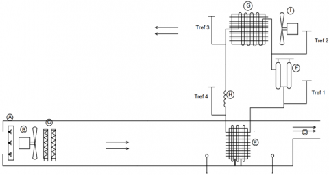
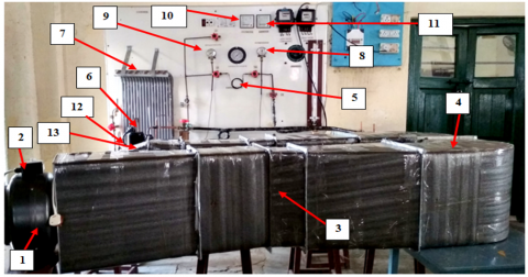
A conventional air conditioning system using an air-cooled condenser is experimentally examined for providing comfort conditions. The main components of a conventional air conditioning unit are compressor, air-cooled condenser, capillary tube and evaporator. Here, in air-cooled condenser, heat transfer takes place from a working fluid (R-410a) to surrounding air. The performance of ACS is investigated at different process air inlet humidity ratios ranging (0.01580-0.01740 kg/kg), at different process air inlet velocities ranging (1.5-4.5 m/s). The experimental setup is installed at Refrigeration and Air Conditioning Lab, Mechanical Engineering Department, ZHCET, Aligarh Muslim University, India. Line diagram and photograph of a practical structure for a conventional air conditioning unit are shown in Figures 1 and 2, respectively.
2.2 Air conditioning system operation
The experimental setup comprises a pretreatment segment, a blower and a vapour compression refrigeration system. The air pretreatment portion contains an electric heater and a humidifier. The incoming air can be heated with electric heaters to the desired temperature and then humidified through a humidifier. After that, hot and humid air is blown through the duct, which passes over the evaporator of the vapour compression refrigeration system. R-410a is used as a refrigerant. When air comes in contact with the cooling coils, it gets cooled below its dew point temperature at a constant pressure. Due to this, some of the water vapour condenses after crossing the dew point line. Conventional vapour compression air conditioning unit tolerates excess sensible heat loads to diminish water vapour content. Sometimes, this procedure is followed by reheating air to a comfortable temperature before introducing it into a conditioned space. Also, here in a conventional vapour compression air conditioning unit, the evaporator has to handle both sensible and latent load.
2.3 Desiccant air conditioning system with complete waste heat reclamation
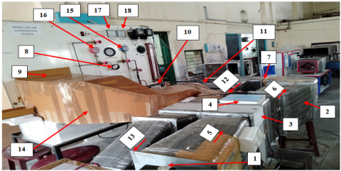
The same experimental setup is integrated with a rotary desiccant wheel which comprises a desiccant air conditioning unit. Therefore, the desiccant cooling system includes the dehumidifier, restoration heat source and cooling unit. Here, a desiccant air conditioning scheme using waste heat rejected out of air cooled condenser for the revival of desiccant wheel. DACS is experimentally investigated at different process air inlet humidity ratios ranging (0.01580-0.01740 kg/kg), at different process air inlet velocities ranging (1.5-4.5 m/s) and at a minimum (2.5 m/s) and a maximum (4.5 m/s) regeneration air inlet velocity. The solid rotary desiccant wheel has been used in an experimental setup. Silica gel has been utilized as a solid desiccant material. Line diagram and photograph of an experimental design for desiccant air conditioning unit utilizing unused heat of condenser for renewal of desiccant wheel are shown in Figures 3 and 4 respectively.
|
A-Humidifier |
H-Capillary Tube |
|
B-Blower |
I-Fan |
|
C-Electrical Heater |
Tref 1- Evaporator Exit Temp |
|
D-Conditioned Space |
Tref 2- Compressor Exit Temp |
|
E-Evaporator |
Tref 3- Condenser Exit Temp |
|
F-Compressor |
Tref 4-Evaporator Inlet Temp |
|
G-Air Cooled Condenser |
|
Figure 1. Line diagram for conventional air conditioning system
|
1- Air In |
7- Air Cooled Condenser |
13- Air Out |
|
2- Blower |
8- Suction Pressure Gauge |
|
|
3- Air Duct |
9- Discharge Pressure Gauge |
|
|
4- Evaporator |
10- Voltmeter |
|
|
5- Capillary tube |
11-Ammeter |
|
|
6- Compressor |
12- Conditioned space |
|
Figure 2. Photograph of experimental set-up for conventional air conditioning system
|
A-Humidifier |
H-Capillary Tube |
5- Comfort Zone |
|
B-Blower |
I-Fan |
Tref 1- Evaporator Exit Temp |
|
C-Electrical Heater |
J- Desiccant Wheel |
Tref 2- Compressor Exit Temp |
|
D-Conditioned Space |
1- Process Air Inlet |
Tref 3- Condenser Exit Temp |
|
E-Evaporator |
2- Process Air Outlet |
Tref 4-Evaporator Inlet Temp |
|
F-Compressor |
4- Regeneration Air Inlet |
|
|
G-Air Cooled Condenser |
3- Regeneration Air Outlet |
|
Figure 3. Line diagram for desiccant air conditioning system with complete waste heat reclamation
|
1- Blower |
8- Capillary tube |
15- Suction Pressure Gauge |
|
2- Air Duct |
9- Condenser |
16- Discharge Pressure Gauge |
|
3- Desiccant Wheel |
10- Compressor |
17- Voltmeter |
|
4- Data logger |
11- Conditioned space |
18-Ammeter |
|
5- Process Air In |
12- Regeneration Air In |
|
|
6- Process Air Out |
13-Regeneration Air Out |
|
|
7- Evaporator |
14- Waste Heat Reclamation |
|
Figure 4. Photograph of an experimental setup for desiccant air conditioning system with complete waste heat reclamation
2.4 Desiccant air conditioning system operation
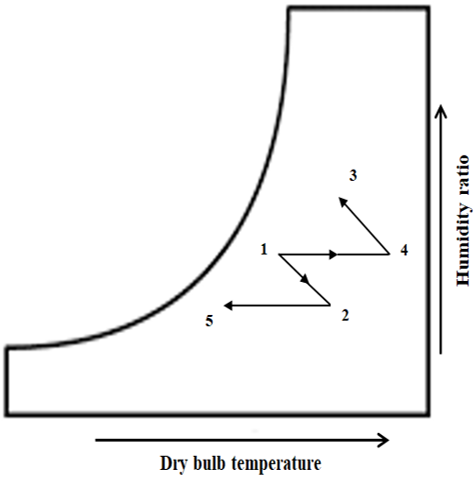
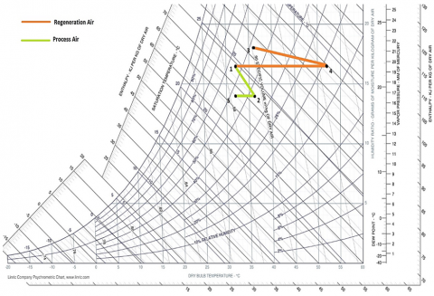
The experimental setup comprises a pretreatment segment, a rotary desiccant wheel and a vapour compression refrigeration system. Process air can be heated with electric heaters to needed temperature and further humidified through a humidifier. When processed air streams over the desiccant exterior in the adsorption segment, its vapour pressure is higher than the desiccant exterior because of more humid air conditions, which generates a significant difference. This water vapour is adsorbed outward of the desiccant and is condensed above it. Then the air passes over the cooling coil of the vapour compression refrigeration unit and sensibly drops down to the ideal temperature. In the regeneration sector, when complete waste heat from the condenser (regeneration air) streams over the desiccant exterior in the regeneration segment, it heats desiccant external. It increases its vapour pressure, increasing the difference between desiccant surface and restoration air. Thus, restoration air evaporates moisture from a desiccant layer. Desiccant air conditioning works by firstly drying air via contact with desiccant, then sensible cooling of air through a split cooling coil, hence providing a distinct control of humidity and temperature. Here, the desiccant wheel will handle the full latent load. Therefore, the cooling coil of the desiccant air conditioning system has to take only a sensible load, ultimately enhancing the hybrid system's performance. Thus, the chief advantage of a solid desiccant air conditioning system is that it separately controls the sensible and latent load. Figure 5 shows psychrometric processes during desiccant air conditioning system with complete waste heat reclamation. Process (1-2) shows the adsorption process which occur at adsorption segment of desiccant wheel where the moisture from incoming processed air is adsorbed on the surface of desiccant. Then process (4-3) shows the regeneration process which occur at regeneration segment of desiccant wheel where the surface of desiccant releases the moisture to incoming regenerated air. Then process (2-5) shows the sensible cooling which occur at cooling coil of VCRS where the refrigerant absorbs heat from air coming out of process sector of desiccant and thus provides the sensible cooling of air. Then process (1-4) shows the sensible heating of air using complete waste heat liberated out of condenser where the refrigerant in VCRS changes its phase and rejected its heat to surrounding air and provides the sensible heating of air.
2.5 Details of a solid desiccant wheel
Table 1 shows the details of a rotary solid desiccant wheel.
2.6 Assessing device and instruments
Dry bulb temperature and relative humidity of air are measured through a data logger. An anemometer measures air velocity. Table 2 shows the assessing devices and instruments.
2.7 Uncertainty analysis
The error investigation completed in the present work depends on root sum square strategy detailed by Kline [16], the performance parameters described in this work as VCOP, ECOP, wheel effectiveness in adsorption sector, adsorption rate, DCOP, wheel effectiveness in the regeneration sector and regeneration rate are found via calculation from noted variables such as relative humidity, temperature and velocity of air is described thru a recognized value of uncertainty. The comparative uncertainty values obtained for the considered factors are 9.5% for VCOP, 9.2% for ECOP, 6.1% for dehumidification effectiveness, 6.5% for moisture removal capacity, 7.1% for DCOP, 14.1% for regeneration effectiveness and 14.3% for regeneration rate.
Figure 5. Psychrometric processes during desiccant air conditioning system with complete waste heat reclamation
Table 1. Details of a rotary solid desiccant wheel
|
Parameter |
Value |
|
Length of a wheel (m) |
0.1 |
|
Diameter of a wheel (m) |
0.37 |
|
Desiccant material |
Silica Gel |
|
Silica gel specific heat, (J/kgK) |
921 |
|
Silica gel thermal conductivity, (W/mK) |
0.175 |
|
Silica gel density, (kg/m3) |
1129 |
|
The radius of Pore, (m) |
11 × 10−10 |
|
Desiccant Volume ratio |
0.48 |
|
Width of channel wall, (m) |
0.00034 |
|
Pitch of the flow passage, (m) |
0.0032 |
|
Height of the flow passage, (m) |
0.0018 |
Table 2. Assessing device and Instruments
|
Equipment |
Voltage |
Sampling Rate |
Range |
Accuracy |
|
Tweex Data Logger |
Single Phase 220V Standard supply |
5 seconds to 255 minutes |
-10 to +85℃ 0 to 100 %RH |
±0.5℃ ±2.5% |
|
Digital Anemometer |
3.0 V DC |
- |
0 to 30 m/s |
±5% |
3.1 Key processes Involved
These are the main processes in the desiccant air conditioning system using waste heat from the condenser for regeneration. One set of readings is plotted on the psychrometric chart to demonstrate these fundamental processes, as shown in Figure 6.
Adsorption process (1-2): Humid air flows through the adsorption section, as shown in Figure 6. Dry bulb temperature (DBT), relative humidity (RH) and humidity ratio (ω) of air are measured at the inlet of the desiccant wheel, i.e. (32℃ DBT, 55% RH & 0.01649 kg/kg). From the humid air, the adsorption section adsorbs the dampness. At the outlet of the adsorption sector, relative humidity and dry bulb temperature of the air is measured. On the desiccant surface, this moisture is adsorbed and condensed over it. The temperature of process air rises due to heat released from the adsorption process. Before the adsorption section, the pretreatment section of air is installed to control the relative humidity and dry bulb temperature of incoming air.
Waste heat reclamation (1-4): The heat rejected out of the condenser is connected through the regeneration duct. Waste heat extracted from the condenser is allowed to flow through the regeneration sector by a condenser fan. At the inlet of the regeneration sector, relative humidity (17.5%), dry-bulb temperature (53℃) and humidity ratio (0.01576 kg/kg) of the air is measured. Air velocity at the inlet of the regeneration is also varied in this work to get the optimum value.
Sensible cooling (2-5): Sensible cooling is done by evaporator coil of vapour compression refrigeration system. Air at relatively lower humidity (low latent load) and somewhat higher temperature (more sensible load) pass over the evaporator coil. Now the air has less latent load, which effectively increases the coefficient of performance (COP) of the desiccant air conditioning system and results in low energy consumption.
Regeneration process (4-3): In the regeneration sector, waste heat from the condenser is utilized to recover desiccant material. Hot air loses its temperature by evaporating the water vapour from a desiccant layer. At the outlet of the regeneration sector, measurement of dry bulb temperature (36℃), relative humidity (49%) and humidity ratio (0.01842 kg/kg) have taken with the help of a data logger.
Data logger measures the relative humidity and dry bulb temperature of the air at different points. The humidity ratio of air has been calculated from dry bulb temperature and relative humidity using a Psychrometric calculator
Figure 6. Psychrometric processes during desiccant air conditioning system with complete waste heat reclamation
3.2 Operating conditions of air conditioning system
Table 3 shows the operating conditions of ACS.
Table 3. Operating conditions of ACS
|
Parameter |
Value |
|
Compressor |
1073 W |
|
Condenser fan |
100 W |
|
Power of process air fan |
156 W |
3.3 Operating conditions of desiccant air conditioning system with complete waste heat reclamation
Table 4 shows the operating conditions of DACS with complete waste heat reclamation.
Table 4. Operating conditions of DACS with complete waste heat reclamation
|
Parameter |
Value |
|
Compressor |
1073 W |
|
Condenser fan |
100 W |
|
Power of process air fan |
156 W |
|
Desiccant Motor |
115 W |
The various performance parameters which are studied are shown in Eqns. (1-7) for conventional and desiccant air conditioning systems utilizing the waste heat from condenser for renewal at different process air inlet humidity ratios ranging (0.01580-0.01740 kg/kg), at different process air inlet velocities ranging (1.5-4.5 m/s) and at a minimum (2.5 m/s) and a maximum (4.5 m/s) regeneration air inlet velocity:
1. VCOP [17]:
Refrigerating Effect/Compressor Work= (href1 –href4)/ (href2 –href1) (1)
2. ECOP for systems [18]:
Total Cooling Effect/ Total Electric Power Consumption (2)
3. Wheel effectiveness in adsorption sector: symbolizes the ratio between actual and ideal dehumidification ability of desiccant wheel [19].
$\eta_{\mathrm{deh}}=\frac{\omega_{1}-\omega_{2}}{\omega_{1}}$ (3)
4. Adsorption rate: signifies mass flow rate of dampness detached via desiccant wheel [19].
$\mathrm{AR}=\rho_{1} \times \dot{V}_{\mathrm{P}} \times\left(\omega_{1}-\omega_{2}\right)$ (4)
5. Dehumidification Coefficient of Performance (DCOP): signifies ratio among thermal power linked to air dehumidification and thermal energy delivered for regeneration process [19].
$\mathrm{DCOP}=\frac{\rho_{1} \times \dot{V}_{P} \times \Delta h_{v_{s}} \times\left(\omega_{1}-\omega_{2}\right)}{\rho_{1} \times \dot{V}_{r e g} \times C_{p} \times\left(T_{4}-T_{1}\right)}=\frac{\dot{V}_{P} \times \Delta h_{v s} \times\left(\omega_{1}-\omega_{2}\right)}{\dot{V}_{r e g} \times\left(h_{4}-h_{1}\right)}$ (5)
The latent heat of vaporization of water $\Delta h_{v s}$ has been assessed employing following empirical cubic function [19].
$\begin{aligned} \Delta h_{v s}=-0.614342 \times 10^{-4} \times T_{1}^{3}+0.0158927 \times 10^{-2} \times T_{1}^{2}-0.236418 \times 10 \times T_{1}+0.250079 \times 10^{4} \end{aligned}$
6. Wheel effectiveness in regeneration sector: implies latent load held by a desiccant wheel about thermal regeneration power needed for adsorption process of desiccant wheel [20].
$\eta_{\text {reg }}=\frac{\omega_{3}-\omega_{4}}{\omega_{4}}$ (6)
7. Regeneration Rate (RR): signifies the mass flow rate of dampness detached by the wheel from the process side at the regeneration side [20, 21].
$\mathrm{RR}=\rho_{1} \times \dot{\mathrm{V}}_{\mathrm{reg}} \times\left(\omega_{3}-\omega_{4}\right)$ (7)
4.1 Variation of VCOP and ECOP for both systems at different process air inlet humidity ratios
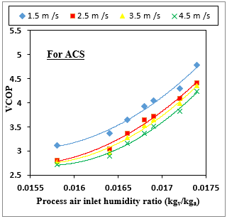
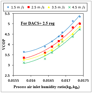
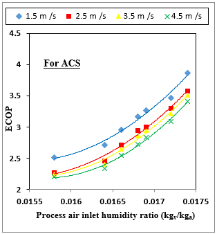
Figures 7-14 show that for both the systems, the value of VCOP and ECOP decreases with a decrease in the different process air inlet humidity ratios ranging (0.01580-0.01740 kg/kg), at different process air inlet velocities ranging (1.5-4.5 m/s) and at a minimum (2.5 m/s) and a maximum (4.5 m/s) regeneration air inlet velocity. As the ambient humidity ratio decreases, there is a rise in ambient temperature and due to which the rate of heat transfer from the condenser decreases. With an increase in ambient temperature, the air-cooled condenser is affected and gets less cooled, increasing the load of the vapour compression refrigeration system. Due to this effect, less heat is absorbed by refrigerant from the air at the evaporator, which ultimately decreases VCOP and ECOP [1, 18].
Figure 7. VCOP variation with process air inlet humidity ratio at different process inlet air velocities for ACS
Figure 8. VCOP variation with process air inlet humidity ratio at different process inlet air velocities for DACS at 2.5 m/s regeneration air inlet velocity
Figure 9. VCOP variation with process air inlet humidity ratio at different process inlet air velocities for DACS at 4.5 m/s regeneration air inlet velocity
Also, Figures 7-14 show that for both systems at all different process air inlet humidity ratios, the value of VCOP and ECOP decrease with rising in different process air inlet velocities ranging (1.5-4.5 m/s) and at a minimum (2.5 m/s) and a maximum (4.5 m/s) regeneration air inlet velocity. More incredible air velocity at the process inlet minimizes the contact time between the surface of the cooling coil and incoming air. Thus, less heat is absorbed by the refrigerant from the incoming air due to lower contact time, which ultimately decreases VCOP and ECOP [18].
Figures 7-10 show that for all different process air inlet velocities ranging (1.5-4.5 m/s), the value of VCOP at different process air inlet humidity ratios ranging (0.01580-0.01740 kg/kg) is higher for desiccant air conditioning unit as compared to conventional air conditioning unit. The regeneration temperature for the desiccant air conditioning with waste heat reclamation is (50-58.8℃). Thus due to high renewal temperature in the revival sector, desiccant material silica gel gets earlier recovered as it releases its moisture content to the incoming regenerated air. Thus, it moves to the adsorption sector, taking moisture from incoming process air. Thus, the desiccant wheel eliminates the latent load. Then, processed air is moved over a cooling coil, which handles only sensible cooling work needed to meet required air conditions for the conditioned area. In comparison, the cooling coil in a conventional air conditioning system has to take both latent and sensible load [18, 22].
Figure 10. VCOP variation with process air inlet humidity ratio at fix 1.5 m/s process air inlet velocity for both the systems
Figure 11. ECOP variation with process air inlet humidity ratio at different process inlet air velocities for ACS
Figure 12. ECOP variation with process air inlet humidity ratio at different process inlet air velocities for DACS at 2.5 m/s regeneration air inlet velocity
Figure 13. ECOP variation with process air inlet humidity ratio at different process inlet air velocities for DACS at 4.5 m/s regeneration air inlet velocity
Figures 11-14 show that the value of ECOP for desiccant air conditioning with complete waste heat reclamation is higher than the traditional air conditioning unit. As in the case of DACS with waste heat reclamation, the refrigerating effect is very high as that of the air conditioning unit. But total electric power consumption in DACS with waste heat reclamation is 1.444 kW and in air conditioning system is 1.329 kW. But for DACS with waste heat reclamation, refrigerating effect dominates the total electric power consumption, and thus its ECOP is more than a conventional air conditioning system [18, 23].
Figures 10 and 14 show that at a fixed (1.5 m/s) process air inlet velocity, the value of VCOP and ECOP increase for DACS with complete waste heat reclamation when air velocity at regeneration inlet declines from a maximum (4.5 m/s) to a minimum (2.5 m/s). It is because lower regeneration air inlet velocity maximizes contact time between desiccant surface and regenerated air. Thus, the higher the desiccant material is restored at a lower regeneration air entry velocity in the regeneration sector. Hence, ultimately this desiccant material in the adsorption sector adsorbs more of the water vapour [18, 24].
Figure 14. ECOP variation with process air inlet humidity ratio at fix 1.5 m/s process air inlet velocity for both the systems
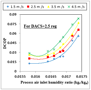
4.2 Variation of wheel effectiveness in adsorption sector, adsorption rate and DCOP for DACS at different process air inlet velocities and humidity ratios
Figures 15-20 illustrate the variation of wheel effectiveness in the adsorption sector, adsorption rate and DCOP for desiccant air conditioning system with complete waste heat reclamation at different process air inlet humidity ratios ranging (0.01580-0.01740 kg/kg), at different process air inlet velocities ranging (1.5-4.5 m/s) and at a minimum (2.5 m/s) and a maximum (4.5 m/s) regeneration air inlet velocity. They display that for all different process air inlet velocities, the value of wheel effectiveness in the adsorption sector, adsorption rate and DCOP for DACS with waste heat reclamation declines with a decrease in process air entry humidity ratios. As process air entry humidity ratio is more, then in the existence of upper water vapour content in process air, there is a significant difference of vapour partial pressure among process air and desiccant wheel, which leads to greater diffusion of water vapour drops from process air to desiccant substantial outward. Hence, an upsurge in humidity ratio of process air entry reasons for an upturn in moisture cycled and raises wheel effectiveness in the adsorption sector. Furthermore, as the incoming air humidity ratio decreases, the partial pressure of water vapour decreases. Lesser inlet humidity ratio drops difference in partial pressure between matrix and air flowing over the desiccant wheel. So, equilibrium properties of desiccant are much favourable for a higher humidity ratio. Since the adsorption process within the dehumidifier is exothermic, it favours a higher humidity ratio of incoming process air for greater wheel effectiveness in the adsorption sector, adsorption rate and DCOP [22, 25].
Figure 15. Wheel Effectiveness in AS variation with process air inlet humidity ratio at different process inlet air velocities for DACS at 2.5 m/s regeneration air inlet velocity
Figure 16. Wheel Effectiveness in AS variation with process air inlet humidity ratio at different process inlet air velocities for DACS at 4.5 m/s regeneration air inlet velocity
Figures 15 and 16 show that the value of wheel effectiveness in the adsorption sector decreases with the increase in the process air inlet velocities for maximum (4.5 m/s) and minimum (2.5 m/s) regeneration air inlet velocity. The higher process air inlet velocity diminishes contact time between desiccant superficial and incoming process air. Thus the lesser amount of water vapour is taken away by the desiccant material due to lower contact time which ultimately decreases the dehumidification effectiveness of the system at higher process air inlet velocity [21].
Figure 17. Adsorption rate (kg/hr) variation with process air inlet humidity ratio at different process inlet air velocities for DACS at 2.5 m/s regeneration air inlet velocity
Figure 18. Adsorption rate (kg/hr) variation with process air inlet humidity ratio at different process inlet air velocities for DACS at 4.5 m/s regeneration air inlet velocity
Figures 17-20 show that the value of adsorption rate and DCOP rises with the process air inlet velocities for maximum (4.5 m/s) and minimum (2.5 m/s) regeneration air inlet velocity. As with an increase in the process air inlet velocity, there is an upturn in process air mass flow rate, which delivers the desiccant wheel with much moist air of which water vapour should be detached and thus ultimately increases adsorption rate and DCOP [25].
Figure 19. DCOP variation with process air inlet humidity ratio at different process inlet air velocities for DACS at 2.5 m/s regeneration air inlet velocity
Figure 20. DCOP variation with process air inlet humidity ratio at different process inlet air velocities for DACS at 4.5 m/s regeneration air inlet velocity
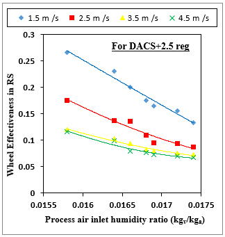
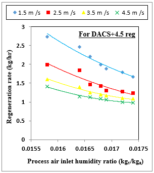
4.3 Variation of wheel effectiveness in regeneration sector and regeneration rate for DACS at different process air inlet velocities and humidity ratios
Figures 21-24 show that for all different process air inlet velocities, the value of wheel effectiveness in regeneration sector and regeneration rate for DACS with complete waste heat reclamation upsurges with a decrease in process air inlet humidity ratio. As the humidity ratio decreases, it also affects restoration temperature, which rises, increasing moisture removal from the desiccant wheel during the regeneration phase. Thus the regeneration rate also increases with a decrease in humidity ratio [20].
Figure 21. Wheel Effectiveness in RS variation with process air inlet humidity ratio at different process inlet air velocities for DACS at 2.5 m/s regeneration air inlet velocity
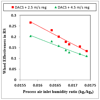
Figure 22. Wheel Effectiveness in RS variation with process air inlet humidity ratio at different process inlet air velocities for DACS at 4.5 m/s regeneration air inlet velocity
Figures 21-24 show that the value of wheel effectiveness in the regeneration sector and regeneration rate decreases with increment in the process air inlet velocities. Higher process air inlet velocity diminishes contact time between desiccant outward and incoming process air. Thus, the desiccant material takes a lesser amount of water vapour due to lower contact time, decreasing the dehumidification effectiveness and ultimately decreasing the system's regeneration effectiveness at higher process air inlet velocity [21].
Figure 23. Regeneration rate (kg/hr) variation with process air inlet humidity ratio at different process inlet air velocities for DACS at 2.5 m/s regeneration air inlet velocity
Figure 24. Regeneration rate (kg/hr) variation with process air inlet humidity ratio at different process inlet air velocities for DACS at 4.5 m/s regeneration air inlet velocity
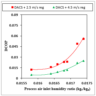
4.4 Variation of wheel effectiveness in adsorption sector, adsorption rate and DCOP for DACS at different humidity ratios and fix (1.5 m/s) velocity of process air inlet
Figures 25-27 show that at a fixed (1.5 m/s) process air inlet velocity, the value of wheel effectiveness in adsorption sector, adsorption rate, DCOP increases for DACS with complete waste heat reclamation when regeneration air inlet velocity decline from maximum (4.5 m/s) to a minimum (2.5 m/s). It is because lower regeneration air inlet velocity maximizes contact time between desiccant superficial and regenerated air. Thus, the higher the desiccant material is restored at a lower regeneration air inlet velocity. Hence, ultimately, this desiccant substantial in adsorption segment adsorbs more of the water vapour [19, 25].
Figure 25. Wheel Effectiveness in AS variation with process air inlet humidity ratio at fix 1.5 m/s process inlet air velocity for DACS at 2.5 m/s and 4.5 m/s regeneration air inlet velocity
Figure 26. Adsorption rate (kg/hr) variation with process air inlet humidity ratio at fix 1.5 m/s process inlet air velocity for DACS at 2.5 m/s and 4.5 m/s regeneration air inlet velocity
4.5 Variation of wheel effectiveness in regeneration sector and regeneration rate for DACS at different humidity ratios and fix (1.5 m/s) velocity of process air inlet
Figures 28 shows that at a fixed (1.5 m/s) process air inlet velocity, the value of wheel effectiveness in the regeneration sector increases when regeneration air entry velocity falls from a maximum (4.5 m/s) to a minimum (2.5 m/s). It is because lower regeneration air inlet velocity maximizes contact time between desiccant surface and regenerated air. Thus, the desiccant material is restored in the regeneration sector at a lower regeneration air entry velocity [20, 21].
Figures 29 displays that at a fixed (1.5 m/s) process air entry velocity, the value of regeneration rate decreases when regeneration air inlet velocity declines from maximum (4.5 m/s) to a minimum (2.5 m/s). It is so, at higher regeneration air inlet velocity, there is an increase in regeneration air mass flow rate, which also provides a desiccant wheel in the regeneration sector with more hot regenerated air, as it removes moisture from the desiccant surface and thus ultimately increases regeneration rate [20, 21, 25].
Figure 27. DCOP variation with process air inlet humidity ratio at fix 1.5 m/s process inlet air velocity for DACS at 2.5 m/s and 4.5 m/s regeneration air inlet velocity
Figure 28. Wheel Effectiveness in RS variation with process air inlet humidity ratio at fix 1.5 m/s process inlet air velocity for DACS at 2.5 m/s and 4.5 m/s regeneration air inlet velocity
Figure 29. Regeneration rate (kg/hr) variation with process air inlet humidity ratio at fix 1.5 m/s process inlet air velocity for DACS at 2.5 m/s and 4.5 m/s regeneration air inlet velocity
The main motive of the present research paper was to compare and analyze the performance of conventional air conditioning system and desiccant air conditioning system using complete waste heat from the condenser (50-58.8℃) for regeneration of desiccant wheel at different process air inlet humidity ratios ranging (0.01580-0.01740 kg/kg), at different process air inlet velocities ranging (1.5-4.5 m/s) and at a minimum (2.5 m/s) and a maximum (4.5 m/s) regeneration air inlet velocity. A key thrust in the research paper has been given to the solid desiccant air conditioning unit because of its benefits of having lesser restoration temperatures, more manoeuvrability, and its ability to be driven by waste heat from the condenser. It was concluded that optimum conditions of performance parameters are identified for the effective working of conventional and hybrid desiccant air conditioning systems under the above operating states, which are as follows:
VCOP and ECOP for both systems (air conditioning system and desiccant air conditioning system with complete waste heat reclamation) decrease with a decrement in different process air inlet humidity ratios, at different process air inlet velocities, at a minimum (2.5 m/s) and a maximum (4.5 m/s) regeneration air inlet velocity.
For the optimum value of VCOP and ECOP, air inlet velocity should be low in both the process and regeneration sectors.
For the optimum value of VCOP and ECOP, the regeneration temperature should be high.
The maximum value of VCOP and ECOP is 5.35 and 3.98 respectively at 0.01740 kg/kg air humidity ratio at process inlet, 1.5 m/s process and 2.5 m/s regeneration air inlet velocity for desiccant air conditioning unit with waste heat reclamation.
Wheel effectiveness in the adsorption sector, adsorption rate and DCOP lower with a decrease in process air inlet humidity ratios.
Wheel effectiveness in the regeneration sector and regeneration rate increase with a decrease in process air inlet humidity ratios.
The regeneration temperature should be high to increase wheel effectiveness in the adsorption sector, adsorption rate, DCOP, wheel effectiveness in the regeneration sector and regeneration rate.
As air velocity at the process inlet increases from 1.5 m/s to 4.5 m/s, wheel effectiveness in the adsorption sector decreases. Whereas, when air velocity at the process entry increases from 1.5 m/s to 4.5 m/s, adsorption rate and DCOP increase.
As air velocity at the regeneration inlet decreases from maximum (4.5 m/s) to minimum (2.5 m/s), the value of wheel effectiveness in the regeneration sector increases. Whereas, when regeneration air inlet velocity decreases from maximum (4.5 m/s) to minimum (2.5 m/s), the value of regeneration rate decreases.
The maximum value of wheel effectiveness in the adsorption sector is 0.03563 for desiccant air conditioning system with waste heat reclamation at 0.01740 kg/kg process air inlet humidity ratio, 1.5 m/s air velocity at process inlet and minimum (2.5 m/s) air velocity at regeneration inlet.
The maximum value of adsorption rate (kg/hr) and DCOP is 0.32550 and 0.08339 respectively for desiccant air conditioning system with waste heat reclamation at 0.01740 kg/kg process air inlet humidity ratio, 4.5 m/s air velocity at process inlet and minimum (2.5 m/s) air velocity at regeneration inlet.
The maximum value of wheel effectiveness in the regeneration sector is 0.26591 for desiccant air conditioning system with complete waste heat reclamation at 0.01580 kg/kg process air inlet humidity ratio, 1.5 m/s process air inlet velocity and minimum (2.5 m/s) regeneration air inlet velocity.
The maximum value of the regeneration rate (kg/hr) is 2.73000 for desiccant air conditioning system with complete waste heat reclamation at 0.01580 kg/kg process air inlet humidity ratio, 1.5 m/s process air inlet velocity and maximum (4.5 m/s) air velocity at regeneration inlet.
For the optimum value of wheel effectiveness in the adsorption sector and wheel effectiveness in the regeneration sector, air inlet velocity should be low in both the adsorption and regeneration sectors.
For optimum adsorption rate and DCOP, air inlet velocity should be high in the adsorption segment and less in the restoration segment.
For the optimum value of regeneration rate, air inlet velocity should be low in the adsorption segment and high in the restoration segment.
Future research activities could be useful with reference to this topic:
• It can be studied which affecting factor has more influence on desiccant wheel performance.
• The effect of regeneration temperatures can also be studied.
Present experimental work was supported by the Technical Education Quality Improvement Program (TEQIP-III), Ministry of Human Resource and Development, Govt. of India. I thankfully acknowledge Voltas India Private Limited for sponsoring 1-ton Window air conditioner (R-410a) to the Refrigeration and Air Conditioning Laboratory of the Mechanical Department, ZHCET, AMU, Aligarh.
|
VCRS |
vapour compression refrigeration system |
|
COP |
coefficient of performance |
|
VCOP |
COP of vapour compression refrigeration system |
|
ECOP |
electric coefficient of performance |
|
DACS |
desiccant air conditioning system |
|
ACS |
air conditioning system |
|
DW |
desiccant wheel |
|
AS |
adsorption sector |
|
RS |
regeneration sector |
|
Tref 1 |
at inlet of compressor temperature of refrigerant (℃) |
|
Tref 2 |
at exit of compressor temperature of refrigerant (℃) |
|
Tref 3 |
at exit of condenser temperature of refrigerant (℃) |
|
Tref 4 |
at inlet of evaporator temperature of refrigerant (℃) |
|
href1 |
at inlet of compressor enthalpy of refrigerant (kJ/kg) |
|
href2 |
at exit of compressor enthalpy of refrigerant (kJ/kg) |
|
href3 |
at exit of condenser enthalpy of refrigerant (kJ/kg) |
|
href4 |
at inlet of evaporator enthalpy of refrigerant (kJ/kg) |
|
DCOP |
dehumidification coefficient of performance |
|
AR |
adsorption rate (kg/hr) |
|
RR |
regeneration rate (kg/hr) |
|
T1 |
at process sector inlet temperature of the air (℃) |
|
T2 |
at process sector outlet temperature of the air (℃) |
|
T4 |
at regeneration sector inlet temperature of the air (℃) |
|
T3 |
at regeneration sector outlet temperature of the air (℃) |
|
ω1 |
at process sector inlet humidity ratio of air (kg/kg) |
|
ω2 |
at process sector outlet humidity ratio of air (kg/kg) |
|
ω4 |
at regeneration sector inlet humidity ratio of air (kg/kg) |
|
ω3 |
at regeneration sector outlet humidity ratio of air (kg/kg) |
|
$\dot{V}$ |
volumetric flow rate ($\mathrm{m}^{3}$/hr) |
|
$c_{p}$ |
air specific heat (kJ/kg K) |
|
Greek symbols |
|
|
$\Delta \mathrm{h}_{\mathrm{vs}}$ |
latent heat of vaporization of water (kJ/kg) |
|
ρ |
density of air (kg/$\mathrm{m}^{3}$) |
|
ω |
humidity ratio or specific humidity (kg/kg) |
|
Subscripts |
|
|
dis |
discharge |
|
P |
process |
|
reg |
regeneration |
|
suc |
suction |
[1] Ansari, A.A., Goyal, V., Yahya, S.M., Hussain, T. (2018). Experimental investigation for performance enhancement of a vapor compression refrigeration system by employing several types of water-cooled condenser. Science and Technology for the Built Environment, 24(7): 793-802. https://doi.org/10.1080/23744731.2018.1423802
[2] Sivak, M. (2009). Potential energy demand for cooling in the 50 largest metropolitan areas of the world: Implications for developing countries. Energy Policy, 37(4): 1382-1384. https://doi.org/10.1016/j.enpol.2008.11.031
[3] Parmar, H., Hindoliya, D.A. (2011). Desiccant cooling system for thermal comfort: A review. International Journal of Engineering Science and Technology, 3(5).
[4] Khoukhi, M. (2013). A study of desiccant-based cooling and dehumidifying system in hot-humid climate. International Journal of Materials, Mechanics and Manufacturing, 1(2): 191-194. https://doi.org/10.7763/IJMMM.2013.V1.41
[5] Zheng, X., Ge, T.S., Wang, R.Z. (2014). Recent progress on desiccant materials for solid desiccant cooling systems. Energy, 74: 280-294. https://doi.org/10.1016/j.energy.2014.07.027
[6] Ando, K., Kodama, A., Hirose, T., Goto, M., Okano, H. (2005). Experimental study on a process design for adsorption desiccant cooling driven with a low-temperature heat. Adsorption, 11(1): 631-636. https://doi.org/10.1007/s10450-005-5997-1
[7] Jalalzadeh-Azar, A.A., Slayzak, S., Judkoff, R., Schaffhauser, T., DeBlasio, R. (2005). Performance assessment of a desiccant cooling system in a chp application with an IC engine. International Journal of Distributed Energy Resources, 1(2): 163-184.
[8] Jia, C.X., Dai, Y.J., Wu, J.Y., Wang, R.Z. (2006). Analysis on a hybrid desiccant air-conditioning system. Applied Thermal Engineering, 26(17-18): 2393-2400. https://doi.org/10.1016/j.applthermaleng.2006.02.016
[9] Fatouh, M., Ibrahim, T.A., Mostafa, A. (2009). Experimental investigation on a solid desiccant system integrated with a R407C compression air conditioner. Energy Conversion and Management, 50(10): 2670-2679. https://doi.org/10.1016/j.enconman.2009.06.020
[10] Mittal, V., Khan, B.K. (2010). Experimental investigation on desiccant air-conditioning system in India. Frontiers of Energy and Power Engineering in China, 4(2): 161-165. https://doi.org/10.1007/s11708-009-0070-5
[11] Mandegari, M.A., Pahlavanzadeh, H. (2010). Performance assessment of hybrid desiccant cooling system at various climates. Energy Efficiency, 3(3): 177-187. https://doi.org/10.1007/s12053-009-9059-5
[12] Lokapure, R.B., Joshi, J.D. (2012). Waste heat recovery through air conditioning system. International Journal of Engineering Research and Development, 5(3): 87-92.
[13] Angrisani, G., Roselli, C., Sasso, M. (2015). Experimental assessment of the energy performance of a hybrid desiccant cooling system and comparison with other air-conditioning technologies. Applied Energy, 138: 533-545. https://doi.org/10.1016/j.apenergy.2014.10.065
[14] Jani, D.B., Mishra, M., Sahoo, P.K. (2016). Solid desiccant air conditioning–A state of the art review. Renewable and Sustainable Energy Reviews, 60: 1451-1469. https://doi.org/10.1016/j.rser.2016.03.031
[15] Belguith S, Slama RB, Chaouachi B, et al. (2020, October). Performance analysis of hybrid solid desiccant-vapor compression air conditioning system: Application and comparative study. In 2020 11th International Renewable Energy Congress (IREC), Hammamet, Tunisia, pp. 1-6. https://doi.org/10.1109/IREC48820.2020.9310373
[16] Kline, S.J. (1953). Describing uncertainty in single sample experiments. Mech. Engineering, 75: 3-8.
[17] Jani, D.B., Mishra, M., Sahoo, P.K. (2015). Performance studies of hybrid solid desiccant–vapor compression air-conditioning system for hot and humid climates. Energy and Buildings, 102: 284-292. https://doi.org/10.1016/j.enbuild.2015.05.055
[18] Dai, Y.J., Wang, R.Z., Zhang, H.F., Yu, J.D. (2001). Use of liquid desiccant cooling to improve the performance of vapor compression air conditioning. Applied Thermal Engineering, 21(12): 1185-1202. https://doi.org/10.1016/S1359-4311(01)00002-3
[19] Angrisani, G., Minichiello, F., Roselli, C., Sasso, M. (2012). Experimental analysis on the dehumidification and thermal performance of a desiccant wheel. Applied Energy, 92: 563-572. https://doi.org/10.1016/j.apenergy.2011.11.071
[20] Angrisani, G., Minichiello, F., Roselli, C., Sasso, M. (2011). Experimental investigation to optimise a desiccant HVAC system coupled to a small size cogenerator. Applied Thermal Engineering, 31(4): 506-512. https://doi.org/10.1016/j.applthermaleng.2010.10.006
[21] Yadav, A. (2012). Experimental and numerical investigation of solar powered solid desiccant dehumidifier. Doctoral dissertation, National Institute of Technology.
[22] Jani, D.B., Mishra, M., Sahoo, P.K. (2016). Performance analysis of hybrid solid desiccant–vapor compression air conditioning system in hot and humid weather of India. Building Services Engineering Research and Technology, 37(5): 523-538. https://doi.org/10.1177/0143624416633605
[23] Yong, L., Sumathy, K., Dai, Y.J., Zhong, J.H., Wang, R.Z. (2006) Experimental study on a hybrid desiccant dehumidification and air conditioning system. Journal of Solar Energy Engineering, 128(1): 77-82. https://doi.org/10.1115/1.2148977
[24] Sumathy, K., Yong, L., Dai, Y.J., Wang, R.Z. (2009). Study on a Novel Hybrid Desiccant Dehumidification and Air Conditioning System. In: Howlett R.J., Jain L.C., Lee S.H. (eds) Sustainability in Energy and Buildings. Springer, Berlin, Heidelberg. https://doi.org/10.1007/978-3-642-03454-1_43
[25] Goodarzia, G., Thirukonda, N., Heidari, S., Akbarzadeh, A., Date, A. (2017). Performance evaluation of solid desiccant wheel regenerated by waste heat or renewable energy. Energy Procedia, 110: 434-439. https://doi.org/10.1016/j.egypro.2017.03.165