Akram H. Abed* | Ayad K. Khlief | Mohammed Hassan Jabal
© 2021 IIETA. This article is published by IIETA and is licensed under the CC BY 4.0 license (http://creativecommons.org/licenses/by/4.0/).
OPEN ACCESS
The steady, internal, and ultrasonic-generated water mist cooling in a uniformly heated vertical cylinder with evaporating subcooled water film has been investigated experimentally. The goal is to elucidate the effects of different operating parameters, viz. water mist concentration, carrier gas velocity, loaded heat flux, and flow orientation on the heat transfer rate and pressure drop characteristics. The experiments were performed in a turbulent flow regime over a range of Reynolds number (from 6000 to 18000) using air as the carrier fluid. Compared with the cylinder without water mist, the results showed that using water mist as a coolant increases the Nusselt numbers along the cylinder, high Nusselt numbers are obtained by suspending the high-water mist and it was about 224% for heat flux q=1.56 kW/m2. The results also showed that the local Nusselt number rapidly decreases as the heat flux increases, this decreasing in the Nusselt number was the most at high heat flux q=4.81 kW/m2, in which the water film early breakdown and the breakdown point gets closer to the entrance region. In addition, a new empirical correlation of the heat transfer rate was proposed to estimate the real benefits in using water mist of the enhanced cylinder.
mist flow, heat transfer enhancement, ultrasonic mist generator, mist deposition, water film, weber number
As ambient temperature increases, especially in hot-arid or subtropical climate regions, conventional single-phase air cooling systems are more difficult to meet the operating conditions and cooling requirements due to the low-cooling performance that limits further enhancement of systems. To overcome this problem, efforts have been made by many researchers to find more efficient coolants that ultimately enhance the cooling performance. Using air/water mist two-phase flow as a coolant is one of the efficient methods of cooling enhancement [1-4], which provides a greatly enhance in heat and mass transfer between heated wall and main flow due to the following features: (a) dissipates a huge amount of energy in the form of latent heat during water mist evaporation process, (b) decreases the bulk temperature of coolant after mixing process, (c) increases specific heat, (d) increases temperature gradient near the heated wall, (e) increases main flow turbulence caused by air/water mist interactions and water mist dynamics, and (f) disturbs the thermal boundary layer near the heated wall [5-11].With the reasons mentioned above, the air/water mist two-phase flow can provide a highly efficient cooling performance and achieve heat transfer rates even higher than those occurring in single-phase air cooling. Although the air cooling method has been used, studied and discussed extensively in several industrial applications, it's only in the last few years ago that more and more investigations have focused on analyzing the air/water mist two-phase flow owing to its complicated nature and difficulty of creating a uniform air/water mist flow. In this axis, Kitagawa et al. [12] experimentally investigated and numerically analyzed the heat transfer characteristics of air/water mist flow in a vertical heated and unheated pipe using atomizing nozzle-mist generator. The water mist was directly injected into the air main flow at the lower end of pipe with average water droplet diameter of 50-70 μm. Their results showed that the heat transfer rate by air/water mist was enhanced approximately seven times over that for single-phase airflow. They also evaluated the droplet deposition velocity to be as 0.3 to 0.43 m/s under experimental conditions. Lee et al. [13] examined experimentally the effect of different operating parameters on the heat transfer characteristics including air and water mist flow velocity, water mist concentration, droplet size, and heat flux in a vertical square duct with a heated surface. The experimental results indicated that, for large droplets case (dp>80 μm), heated wall partially or totally covered by a thick water film and the temperature consequently rises to a high value. For the case of (dp>115 μm), the temperature of heated wall increased to a very high value and the nucleate boiling was appeared to take place at the heated surface. According to Lee et al. [13], the life time of droplet evaporation increase with increases in droplet diameter and therefore, to obtain heat transfer enhancement utilizing evaporative latent heat, the water droplets should have a suitable diameter that enables it to reach heating surface. On the other side, the heating wall must be covered with a water film as ultra-thin as possible to avoid any increase in thermal resistance. Many researchers have analyzed the effect of air/water mist cooling on the heat transfer enhancement in different cooling structures. Alhajeri et al. [14], numerically investigated the influence of mist fraction on heat transfer characteristics of a rotating U-channel with inclined ribs. It was inferred that, at high mist fraction, the flow temperature difference and Nusselt number increased around 300%, and 110% respectively. Mist suspension to steam or gas improves cooling in a variety of applications, including the cooling of gas turbine blades [15-17]. Zhang et al. [18], conducted a numerical calculation to examine different types of coolants, including air, air/water mist, steam, and steam/water mist in a rotating and non-rotating double pass rectangular channel. The numerical results confirmed that the water droplets can enhance the heat transfer in the first pass for the case of Re = 25000 and 40000, while these droplets were unable to survive the 180º turn that occurs in the second pass. For the case of Re = 60000 and 80000, it was indicated that, the average Nusselt number of steams, mist/air, and mist/steam increased around 29%, 11%, and 41% in comparison with that of air cooling respectively. Another numerical simulation and experimental investigation of the mist/steam flow in a rectangular channel roughed with the column-row-ribs conducted by Jiang et al. [19] using atomizing nozzle-mist generator. Their results not only confirmed the effect of the Re number, mist/steam mass ratio, and gap ratio of column-row-ribs, but also were proved that the increasing in droplet diameter will decrease heat transfer performance and thermal enhancement factor.
Based on the previous investigations, this current work aims to investigate experimentally, the effects of the water mist concentration, carrier gas velocity, loaded heat flux, and flow orientation on the heat transfer enhancement of vertical cylinder by employing an ultrasonic atomizer. This work is devoted to clear understanding the flow and heat transfer physics behavior of a fine water mist generated by an ultrasonic mist generator. The water mass fraction is kept less than 10% and is suspended to the carrier gas at the entrance of the test cylinder to achieve the homogeneous mist flow. This work will pose a novel development of water mist cooling as a highly efficient heat transfer cooling method for high average power lasers (HAPL) used in a thermonuclear fusion power plant.
2.1 Experimental apparatus
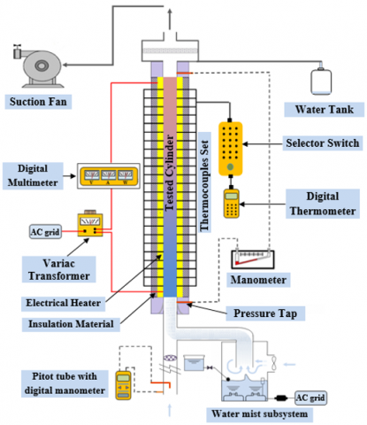
For the current investigation, a fully instrumented experimental apparatus, which is shown schematically in Figure 1, was developed to implement experiments with air and air/water mist flow. The experimental apparatus consists of an air subsystem, water mist subsystem, test cylinder with the heating system, mixing chamber, and data acquisition system. Air subsystem is an open-loop circuit operated in a suction mode using a 1000 W centrifugal fan, in which the inlet air at 25℃ enters the Pitot-static tube flow meter, and then directed to test cylinder section. The carrier gas velocity was measured using a Pitot-static tube that was meticulously designed in accordance with ASME standard [20] and calibrated with a mini anemometer (ut363) type in the measuring range of (0 to 45m/sec) with accuracy (0.5 percent). The pressure difference across the Pitot-static tube was measured using a digital manometer (DT-8890A) type with an accuracy of (±0.3%). To provide a varying fan speed that is needed to obtain the required airflow rate from centrifugal fan, a variac transformer was used. The aluminum test cylinder was 1350 mm long, and the inner and outer diameters were 45 and 50 mm respectively. A well-designed Teflon bell mouth installed at the beginning of the test cylinder was applied to produce a uniform velocity profile (symmetric flow). On the other cylinder side, another Teflon piece was also applied. The Teflon was employed due to its low thermal conductivity, which aids in reducing heat loss from the test cylinder ends. The test cylinder was heated electrically by winding flexible electrical wire along the entire length, and then the outer surface thermally insulated using fiber glass and asbestos layer to minimize the heat losses. The electrical output power from heater was adjusted to obtain the required heat flux by changing the alternating voltage through a transformer. The test cylinder wall temperatures were measured by 38 calibrated thermocouples (K-type) positioned along the entire length of the test cylinder. In addition, the inlet and outlet flow temperatures also measured by four thermocouples positioned at the inlet and outlet section to obtain the bulk air temperature.
Figure 1. Schematic illustration of the experimental apparatus
2.2 High-frequency ultrasonic mist generator
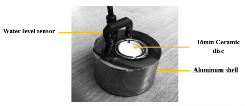
A special-purpose water mist system was designed to generate a fine water droplet (dp<15μm). Three mist generators immersed in a water vessel were used to generate the requirement water mist concentration as shown in Figure 2. The dimensions of the water vessel were (300×200×120mm) for length, width, and height respectively. Water inside vessel was maintained at a steady level by using small mechanical floater and the temperature was kept at 24±1℃. The ultrasonic mist generator was fabricated out of aluminum metal in a cylindrical shape having a diameter of 35mm, and height of 25mm which is shown in Figure 3. Each module consists of piezoelectric transducers coupled to a ceramic disc with a 16 mm diameter operating with high-frequency oscillation of 1.4 MHz. Such modules don’t need heat sources to generate water mist, but utilizes ultrasonic oscillation with low power consumption of 14W. As a result of water irradiated with ultrasonic waves at high-frequency oscillations, the water is separated from the ceramic disc in adiabatic process and creates an acoustic streams and water cavitation. In addition, a cone-shape acoustic fountain is formed above the water surface that's could produce water mist with diameter smaller than those produced by a spray nozzle.
Figure 2. Image of the water mist subsystem (right), and water column formed by ultrasonic mist generator (left)
These droplets can easily diffuse into the main airflow using positive pressure generated by small fan without notable thermal change. To obtain the required water mist concentration, the number of ultrasonic mist generators operating simultaneously can be selected, and also it is possible to regulate the speed of a fan which coupled to the water vessel.
Figure 3. Image of ultrasonic mist generator
2.3 Estimation of water droplet size and distribution
Generation of water mist by ultrasonic generator results in droplets of various sizes depending on the operating frequencies. Therefore, two approaches were adopted to evaluate the water droplet size and describe the droplet distribution of the entire water mist. The first is the capillary wave theory that uses the wavelength of capillary waves produced by the ultrasonic generator depending on the operating frequency. Based on this theory, Lang [21] informed that the water mist diameter is directly proportional to capillary wavelength for a range of frequencies and introduced the following equation.
$d_{p}=0.34 \lambda$ (1)
$\lambda=\left(\frac{8 \pi \sigma}{\rho_{\text {wa }} \varphi^{2}}\right)^{\frac{1}{3}}$ (2)
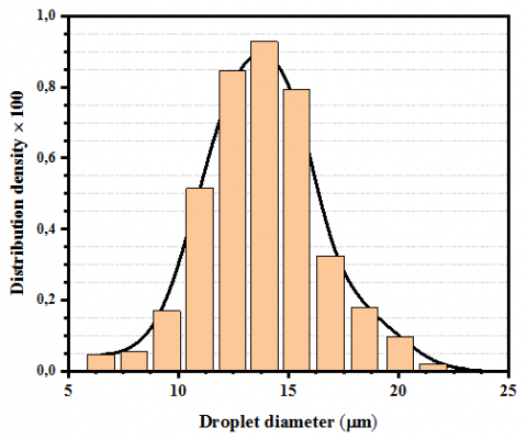
According to the Lang equation mentioned above, the water mist diameter generated by 1.4 MHz is computed to be 12.7 μm. The second approach is the application of an experimental method using the droplets deposition technique on a glass plate coated with an oily film, followed by microscopic photography and processing in order to obtain the size and distribution of water droplets. An optical microscope type (DCM510, 5M pixels) equipped with a digital camera (micromed r-1) type that is connected to a computer was used to allowing observation of a water mist sample. In the middle part of the microscope stage, installed a glass plate coated with an oily film incorporated with two parallel wires having different diameters of 10 and 25 microns as scale for determining the diameter of water droplets. The composition of suspended water mist is shown in Figure 4 in the form of the droplet distribution density as a function of droplets size. Most of the droplets were found less than 10-15 μm in size, which indicates their closeness to the calculated value by Lang equation.
Figure 4. Water mist size distribution produced by the ultrasonic atomization
At steady-state condition, the convective heat transfer coefficients and the corresponding Nusselt numbers between heated cylinder’s wall and passing air/water mist flow were determined according to the proposed and existing heat transfer relationships reported in the literature. In each test, the heat transfer coefficients are determined by the net heat transferred from the electrical heater to passing flow across the cylinder walls and the temperature difference between them as follow:
$Q_{1}=\dot{V_{\text {input }} \cdot I_{\text {input }}-Q_{\text {loss. }}}=Q$ (3)
$Q_{2}=m \cdot C_{p} \cdot\left(T_{b, o}-T_{b, i}\right)=h \cdot A_{t t} \cdot\left(T_{w}-T_{b}\right)=Q$ (4)
$h_{x}=\frac{Q}{A_{t t} \cdot\left(T_{x, w}-T_{b}\right)}$ (5)
where, Tx,w is the local wall temperature, Tb is the bulk temperature calculated from the inlet and outlet flow temperatures as follow:
$T_{b}=\frac{\left(T_{b, o}+T_{b, i}\right)}{2}$ (6)
The local Nusselt number (Nu) can be estimated from the relation.
$N u_{x}=\frac{h_{x} \cdot D_{h}}{k}$ (7)
In relation (7), Dh is the hydraulic diameter of the test cylinder determined as relation (8), and k is the thermal conductivity of the passing flow.
$D_{h}=\frac{4 A_{t t}}{P}$ (8)
The mean heat transfer coefficient is determined from the relation.
$\bar{h}=\frac{\sum_{i=1}^{38}\left(h_{x, 1}+h_{x, 2}+\ldots \ldots+h_{x, 38}\right)}{38}$ (9)
The dispersed Reynolds number is estimated as relation (10) based on the relative velocity between the water mist and the carrier gas [22].
$R e_{d}=\frac{(U+u) \cdot D_{h}}{v_{f}}$ (10)
Friction factor can be estimated from the relation.
$f=\frac{\Delta P}{\left(\frac{L}{D_{h}}\right)\left(\frac{\rho_{f} U^{2}}{2 g}\right)}$ (11)
Generally, when analyzing the interaction between water mist and air, the heat transfer between them is always connected with mass transfer. The energy conservation equation of water droplet in the form of the total heat carried by water mist and latent heat of evaporation with neglecting the radiation effect was considered as follow:
$m_{p} C_{p} \frac{d T}{d \tau}=\pi d_{p}^{2} h_{m}\left(T-T_{p}\right)+\frac{d m_{p}}{d \tau} h_{f g}$ (12)
where, dmp/dτ is the change of mass transfer rate by evaporation estimated by the relation below:
$\frac{d m_{p}}{d \tau}=-h_{m} A_{p}\left(C_{s}-C_{o}\right)$ (13)
where, Co, Cs are respectively the concentration of the vapor at the bulk flow and the droplet surface.
$\frac{d u_{p}}{d \tau}=\frac{18 \mu}{\rho_{p} D_{p}^{2}} \frac{C_{d} R e}{24\left(u-u_{p}\right)}$ (14)
The Weber number is described in ref. [23].
$W e=\frac{m^{2} d_{p}}{A \rho_{w a} \sigma}$ (15)
The Ohnesorge number is described in ref. [24].
$O h=\frac{\mu}{\sqrt{\rho_{w a} \sigma d_{p}}}$ (16)
The mist fractional deposition in the test cylinder is estimated from the relation based on the mass flow rate of water mist at inlet and outlet of the test cylinder.
$F_{D}=\frac{M_{w, \text { in }}-M_{w, \text { out }}}{M_{w, i n}}$ (17)
where, Mw,in and Mw,out is the mass flow rate of the water mist in the carrier air at inlet and outlet of the test cylinder. The water mist deposition coefficient (kD) is then estimated from the mass balance as follow:
$K_{D}=-\frac{U}{4} \frac{D_{h}}{L} \ln \left(1-F_{D}\right)$ (18)
The dimensionless deposition coefficient has the form.
$K_{D}^{*}=\frac{K_{D}}{u^{*}}$ (19)
where, u* is the friction velocity calculated from the measured pressure drop along the test cylinder as follow:
$u^{*}=\left(\frac{\Delta P D_{h}}{4 \rho_{f} L}\right)^{0.5}$ (20)
Based on the Stokes drag force, the dimensionless relaxation time of the water mist is estimated from the relation (21) as follow:
$\tau^{*}=\left(\frac{d_{p} \rho_{a} \rho_{w a} u^{* 2}}{18 \mu_{a}^{2}}\right)$ (21)
The dimensionless mist concentration in the carrier air, at the inlet of the test cylinder is determined as:
$C_{w, \text { in }}=\frac{M_{w a, \text { in }}}{M_{a} / \rho_{a}}$ (22)
The error analysis and uncertainties of the obtained experimental results were specified according to the standard method presented in ref. [25, 26]. Three important parameters for the current study are: (1) Nusselt number, (2) Reynolds number, and (3) friction factor. Uncertainty of Nusselt number can be computed by the following relation.
$\left(\frac{\Delta N u}{N u}\right)^{2}=\frac{1}{N u}\left[\left(\frac{\partial}{\partial h}(N u) \Delta h\right)^{2}+\left(\frac{\partial}{\partial D_{h}}(N u) \Delta D_{h}\right)^{2}\right.$
$\left.+\left(\frac{\partial}{\partial k}(N u) \Delta k\right)^{2}\right]$ (23)
$\left(\frac{\Delta h}{h}\right)^{2}=\frac{1}{h}\left[\left(\frac{\partial}{\partial q}(h) \Delta q\right)^{2}+\left(\frac{\partial}{\partial T_{w}}(h) \Delta T_{w}\right)^{2}\right.$
$\left.+\left(\frac{\partial}{\partial T_{b}}(h) \Delta T_{b}\right)^{2}\right]$ (24)
$\begin{aligned}\left(\frac{\Delta R e}{R e}\right)^{2}=\frac{1}{R e} &\left[\left(\frac{\partial}{\partial u}(R e) \Delta(u)\right)^{2}+\left(\frac{\partial}{\partial \rho}(R e) \Delta \rho\right)^{2}\right.\\ &\left.+\left(\frac{\partial}{\partial D_{h}}(R e) \Delta D_{h}\right)^{2}+\left(\frac{\partial}{\partial \mu}(R e) \Delta \mu\right)^{2}\right] \end{aligned}$ (25)
$\begin{aligned}\left(\frac{\Delta f}{f}\right)^{2}=\frac{1}{f}\left[\left(\frac{\partial}{\partial \Delta P}\right.\right.&(f) \Delta(\Delta P))^{2}+\left(\frac{\partial}{\partial L}(f) \Delta L\right)^{2} \\ &\left.+\left(\frac{\partial}{\partial D_{h}}(f) \Delta D_{h}\right)^{2}+\left(\frac{\partial}{\partial R e}(f) \Delta R e\right)^{2}\right] \end{aligned}$ (26)
The maximum uncertainties were found to be 5.7%, 4% and 7%, for Nusselt number, Reynolds number and friction factor respectively.
5.1 Single-phase heat transfer results
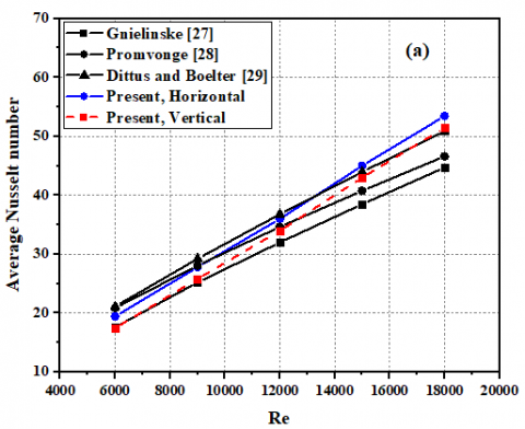
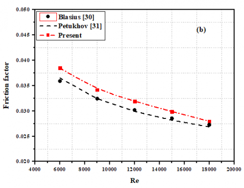
Figure 5. Verification of (a) Nusselt number and (b) friction factor for a cylinder without mist
Before performing systematic experiments on the heat transfer with air/water mist flow, some experimental runs with single-phase flow were conducted to prove the reliability of the experimental apparatus as well as to obtain the reference data for comparison with subsequent results. A comparison was made between the experimental results obtained from the related experiments and previous empirical correlations suggested by Gnielinske [27], Promvonge [28], Dittus–Boelter [29], for Nusselt number, and Blasius [30], Petkhov [31], for friction factor under similar conditions as shown in Figure 5. In this Figure the Nusselt number agree well with the those from the Gnielinske correlation within ±5.3, while friction factor data are within ±5.2% of those from the Blasius correlation.
5.2 Mist flow heat transfer results
5.2.1 Effect of mist concentration
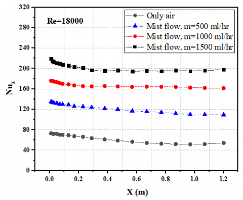
Figure 6. Local Nusselt number through the cylinder for different mist concentration under constant heat flux (q=1.56 kW/m2)
One of the most important factors influencing the mist cooling performance is the water mist concentration. Evidently, as long as there is a sufficient amount of water mist in the flow to form an ultra-thin water film on the cylinder walls, an evaporation process would occur, which ultimately enhance the cooling performance. However, there is a limit to the water amount that can be carried by the carrier air under a condition of certain main airflow rate. Furthermore, suspending a large amount of water into carrier air causes flood and overcool the cylinder wall. Figure 6 shows the variations of local Nusselt number with the cylinder axial distance (x) according to different mist concentration and Reynolds numbers. It can be clearly observed that the Nusselt number increases with increasing the mist concentration under the same Reynolds number. At the entrance region of the cylinder, high Nusselt number is obtained due to the high-water mist deposition, which forms stable ultra-thin water film. Consequently, increase in the convective component of the water film heat transfer rate with increasing mist concentration. Beyond the maximum value, the Nusselt number gradually decreases until minimum value at the point of onset of water film breakdown. As the mist concentration decreases, the high Nusselt number region significantly decreases due to the reduction in mist deposition, which produce a thinner, unstable water film.
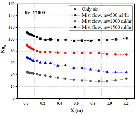
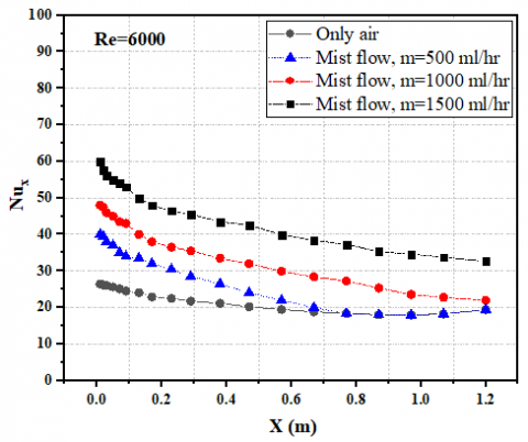
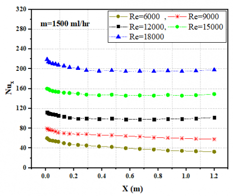
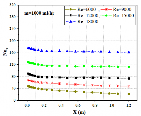
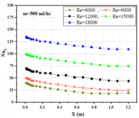
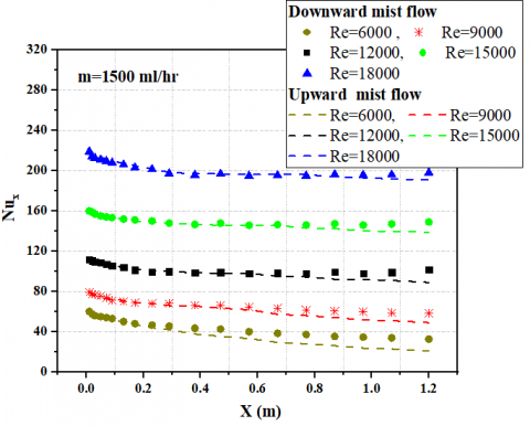
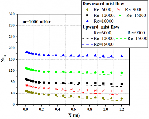
Figure 7. Local Nusselt number through the cylinder for different Reynolds numbers under constant heat flux (q=1.56 kW/m2)
It should be noted that, in addition to mist deposition in the entrance region, the smaller number of water mist moves in the downward region may also enhance the evaporation process and effectively increasing the relative humidity of the surrounding air and thus further increasing the Nusselt number. For the downward mist flow with Re = 18,000, the average Nusselt number of air/water mist flow is enhanced by 225%, 184% and 96% in comparison with the air cooling respectively.
5.2.2 Effect of Reynolds number
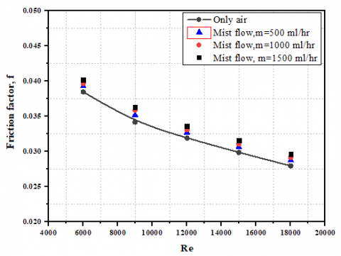
Similar to water mist concentration, the inlet carrier air velocity, i.e., Reynolds number is also affecting the performance of mist cooling through its effect on water mist transport from the mixing chamber to the test cylinder. Figure 7 shows the variations of local Nusselt number for downward mist flow over a range of Reynolds numbers (from 6000 to 18000), and water mist concentration of 500, 1000, and 1500 ml/hour. With higher carrier air velocity (Reynold number up to 12000), the drag forces imposed by the carrier air can rapidly increase slip and allowing the water mist to independently penetrate further down the test cylinder. As a result, the water mist will deposit along the entire test cylinder, thereby enhancing the heat transfer rate in the entrance as well as downstream regions. Conversely, low carrier air velocity allows the water mist to rapidly deposit on the entrance region, thereby starving the downstream region of the cylinder. As can be clearly observed in Figure 7, where the experiment using high water mist concentration, the local Nusselt number with Reynold number Re=6000 has a higher value at the entrance region compared to that for the downstream region. The local Nusselt number decreases nearly one-third of the way along the test cylinder, at approximately (x=0.38 m), indicating the early water mist deposit. While high carrier air velocity case, Re=18000, shows a better local Nusselt number at the entrance region as well as along the test cylinder due to the reduction in water film thickness in the entrance region, and also better water mist distribution along the test cylinder. Figure 8 shows the effect of using water mist on the pressure drop in the terms of friction factor for all cases of water mist concentration. The friction factor shows a decreasing tendency with increasing Reynolds number. It is obvious that the use of the water mist leads to a slight increase in friction factor above the air cooling, this increasing in the friction factor was the most at high water mist concentration and it was around 6%.
Figure 8. Effect of mist concentration on the friction factor (f) for different Reynolds number
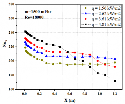
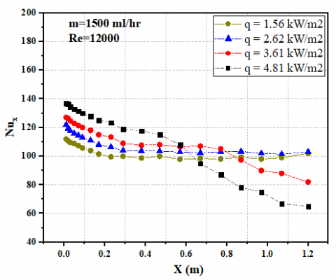
Figure 9. Effect of loaded heat flux on the local Nusselt number through the cylinder
5.2.3 Effect of loaded heat flux
Compared to single-phase forced convection where the heat transfer rate is unaffected by heat flux, the heat transfer rate of mist flow with their evaporation is highly affected by heat flux. Figure 9 shows the effect of wall heat flux on the local Nusselt number for downward mist flow over a range of Reynolds number. It can be clearly observed that the local Nusselt number increases with increasing heat flux as long as the water film remains intact. This may be due to the fact that high heat flux increases the water film temperature, as a result, the evaporation process at the water film-carrier air interface is improved, leading to increase local Nusselt number, i.e., lower thermal resistance. As the heat flux increases (q up to 2.26 kW/m2), the local Nusselt number rapidly decreases nearly two-thirds of the way along the test cylinder, at approximately (x=0.88 m), indicating the early water film breakdown. At high heat flux (q=4.81 kW/m2), the film becomes unstable and breakdown point gets closer to the entrance region at approximately (x=0.6 m). Hence, it can be concluded that the thinner water film (i.e., lower water mist concentration) is less resistant to the onset of breakdown than a thicker film, by assuming they both have the same heat flux. This provides an obvious proof that the heat transfer mechanism is evaporation-driven.
5.2.4 Flow orientation
Some experiments have been performed to clarify the effect of flow orientation (downward versus upward flow) on water mist cooling behavior. In Figure 10, the variations of local Nusselt number with the cylinder axial distance (x) according to flow orientation over a range of heat flux for different mist concentration are shown respectively. In downward mist flow, as long as water mist reaches the wall, the gravitational forces assist to disperse water mist circumferentially while maintaining a uniform distribution of water mist along the cylinder. These benefits are not apparent in case of upward mist flow. Gravitational force causes a quickly deposition of water mist in entrance region than in the downward flow under constant mist concentration. High water mist deposition allows the film to reach higher temperatures without breakdown. But the film thickness increase is not considerable enough to hinder the evaporation process as shown by the high local Nusselt numbers at the entrance region. Interesting results are shown in these figures, where the local Nusselt number for upward flow early decreases nearly one-third of the way along the test cylinder. Accordingly, the length of the cylinder for upward flow considered to be an important parameter affecting the mist cooling effectiveness. Even at high heat fluxes, film breakdown cannot occur over the entire length of short cylinder, so downward mist flow is advisable for high heat flux applications with short cylinders.
Figure 10. Effect of mist flow orientation on the local Nusselt number through the cylinder
5.3 Measurements of water mist deposition
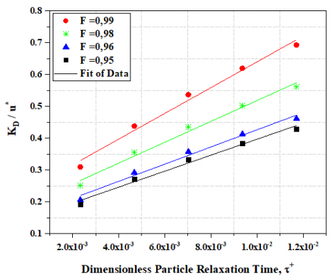
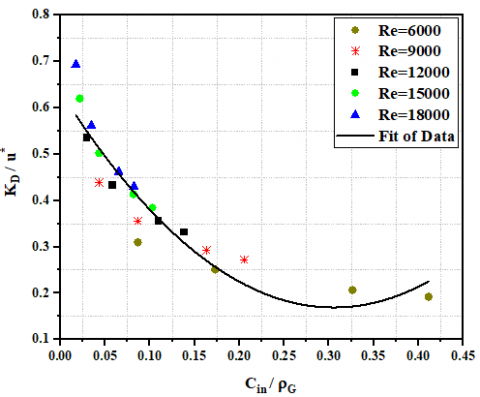
The water mist deposition including two sequential processes: mist transport from the mixing chamber to the test cylinder and mist adhesion at the wall. A mathematical model which is depend on mist sticking efficiency into the cylinder wall, was adopted to predict the mist deposition on the cylinder wall. Figure 11 shows the variations of dimensionless mist deposition coefficient KD for upward flow with the dimensionless relaxation time τ+ over a range of mist fractional deposition. The general pattern was found that the deposition coefficient and mist relaxation time were linearly proportional. This could be connected to the increment in the amount of water mist suspended in the flow with increasing mist fractional deposition, which resulted in delayed mist evaporation. Reynold number is also affecting the mist deposition coefficient. Despite the higher mist concentration, a lower deposition coefficient may result due to the decrease in the carrier gas velocity which allows the water mist to quickly deposit on the entrance region, thereby starving the downstream region of the test cylinder as clearly observed in Figure 12 Hence, it can be concluded that high water mist concentration is preferred since they produce high Nusselt numbers and, more importantly, delay mist evaporation until a much longer axial distance is reached.
Figure 11. Dimensionless mist deposition coefficient for different fractional deposition and fixed Reynolds number Re=18000
Figure 12. Dimensionless mist deposition coefficient for different Reynolds number
5.4 Empirical correlations
The experimental results of the average Nusselt number and friction factor of the test cylinder with air and air/water mist flow are adopted to develop the empirical correlations for further practical use. With the help of least square regression analysis, the empirical correlations for cylinder without water mist was developed as a function of Reynolds number and Prandtl number as shown in Eqns. (27-28).
$N u=0.038 \cdot R e^{0.752} \cdot P r^{0.4}$ (27)
$f=0.478 \cdot R e^{-0.287}$ (28)
For a cylinder with water mist, an empirical correlation for the wet region was developed taking into account Reynolds number, Weber number, and the parameter of the water phase transition (i.e., latent heat of evaporation) as shown in Eq. (29). To assess the accuracy of the correlations, the predicted data from the obtained correlations are compared with experimental results. The deviations of the predicted data from the experimental results are within ±8%.
$N u=3.751 \cdot R e^{0.65} \cdot W e^{0.11} \frac{h_{f g}}{C_{w} \Delta T}^{0.19}$ (29)
In this work, attempts have been made to analyze the heat transfer and pressure drop characteristics during the evaporation of subcooled water film of a uniformly heated vertical cylinder using ultrasonic-generated mist flow. Based on the results of the experimental investigations, the following conclusions can be drawn.
|
T |
Temperature, ℃. |
|
A |
Area, m2 |
|
q |
heat flux, W/m2 |
|
Dh h |
hydraulic diameter, m heat transfer coefficient, W/m2.K |
|
hm |
mass transfer coefficient, m/s |
|
hfg |
latent heat of evaporation, kJ/kg |
|
Nu |
Nusselt number |
|
Re |
Reynolds number |
|
We |
Weber number |
|
Oh |
Ohnesorge number |
|
Pr |
Prandtl number |
|
u* |
friction velocity, m/s |
|
u |
mist velocity, m/s |
|
U |
Gas velocity, m/s |
|
FD |
fractional deposition |
|
KD |
deposition coefficient, m/s |
|
KD* |
dimensionless deposition coefficient |
|
dp |
diameter of droplet, µm |
|
Cp |
specific heat. J/kg K |
|
V |
voltage, volt |
|
I |
current, ampere |
|
Greek symbols |
|
|
φ |
ultrasonic frequency, Hz |
|
ρ |
density, kg/m3 |
|
τ* |
dimensionless relaxation time |
|
µ |
dynamic viscosity, kg/s m |
|
σ |
surface tension, N/m. |
|
Subscripts |
|
|
b |
bulk temperature, ℃. |
|
b,o |
out bulk temperature, ℃. |
|
b,i |
in bulk temperature, ℃. |
|
w |
wall |
|
wa |
Water |
|
wa,in |
Water in |
|
x |
local |
|
p |
droplet |
|
tt |
cylinder |
|
a |
air |
[1] Gandhi, N., Suresh, S. (2020). Effect of mist concentration on the cooling effectiveness of a diffused hole mist cooling system. Journal of Thermal Analysis and Calorimetry, 141(6): 2231-2238. https://doi.org/10.1007/s10973-020-09680-1
[2] Amer, O., Boukhanouf, R., Ibrahim, H.G. (2015). A review of evaporative cooling technologies. International Journal of Environmental Science and Development, 6(2): 111. http://dx.doi.org/10.1016/j.rser.2012.01.052
[3] Huang, K.T., Liu, Y.H. (2019). Enhancement of mist flow cooling by using V-shaped broken ribs. Energies, 12(19): 3785. https://doi.org/10.3390/en12193785
[4] Nirmalan, N.V., Weaver, J.A., Hylton, L.D. (1998). An experimental study of turbine vane heat transfer with water–air cooling. Journal of Turbomachinery, 120(1): 50-62. https://doi.org/10.1115/1.2841387
[5] Sun, G., Hewitt, G.F. (2001). Evaporation and condensation of steam-water in a vertical tube. Nuclear Engineering and Design, 207(2): 137-145. https://doi.org/10.1016/s0029-5493(01)00348-x
[6] Abed, A.H., Shcheklein, S.E., Pakhaluev, V.M. (2019). Experimental investigation of hydrodynamics and heat transfer of sphere cooling using air/water mist two phase flow. In IOP Conference Series: Materials Science and Engineering, 552(1): 012001. https://doi.org/10.1088/1757-899x/552/1/012001
[7] Tan, X., Zhang, J., Liu, B., Zhu, X. (2013). Experimental investigation on heat transfer enhancement of mist/air impingement jet. Science China Technological Sciences, 56(10): 2456-2464. https://doi.org/10.1007/s11431-013-5321-3
[8] Pakhomov, M.A., Terekhov, V.I. (2010). Enhancement of an impingement heat transfer between turbulent mist jet and flat surface. International Journal of Heat and Mass Transfer, 53(15-16): 3156-3165. https://doi.org/10.1016/j.ijheatmasstransfer.2010.03.011
[9] Wang, T., Dhanasekaran, T.S. (2010). Calibration of a computational model to predict mist/steam impinging jets cooling with an application to gas turbine blades. Journal of Heat Transfer, 132(12). https://doi.org/10.1115/1.4002394
[10] Li, X., Gaddis, J.L., Wang, T. (2001). Mist/steam heat transfer in confined slot jet impingement. Journal of Turbomachinery, 123(1): 161-167. https://doi.org/10.1115/1.1331536
[11] Lin, L.C., Ponnappan, R. (2003). Heat transfer characteristics of spray cooling in a closed loop. International Journal of Heat and Mass Transfer, 46(20): 3737-3746. https://doi.org/10.1016/S0017-9310(03)00217-5
[12] Kitagawa, T., Torii, K., Nishino, K. (1998). Heat transfer of air‐water dispersed flow in a vertical pipe. Heat Transfer‐Japanese Research: Co‐sponsored by the Society of Chemical Engineers of Japan and the Heat Transfer Division of ASME, 27(4): 255-270. https://doi.org/10.1002/(sici)1520-6556(1998)27:4<255::aid-htj1>3.0.co;2-u
[13] Lee, S.L., Yang, Z.H., Hsyua, Y. (1994). Cooling of a heated surface by mist flow. Journal of Heat Transfer, 116(1): 167-172. https://doi.org/10.1115/1.2910851
[14] Alhajeri, H.M., Alenezi, A.H., Almutairi, A., Alhajeri, M.H., Gamil, A.A. (2019). Effects of mist fractions on heat transfer characteristics in a rotating roughened cooling passage. Case Studies in Thermal Engineering, 14: 100506. https://doi.org/10.1016/j.csite.2019.100506
[15] Guo, T., Wang, T., Gaddis, J.L. (2000). Mist/steam cooling in a heated horizontal tube—Part 1: Experimental system. Journal of Turbomachinery, 122(2): 360-365. https://doi.org/10.1115/1.555460
[16] Guo, T., Wang, T., Gaddis, J.L. (2000). Mist/steam cooling in a heated horizontal tube—Part 2: Results and modeling. Journal of Turbomachinery, 122(2): 366-374. https://doi.org/10.1115/99-gt-145
[17] Guo, T., Wang, T., Gaddis, J.L. (2000). Mist/steam cooling in a 180-degree tube bend. Journal of Heat Transfer, 122(4): 749-756. https://doi.org/10.1115/1.1287794
[18] Zhang, F., Wang, X., Li, J. (2015). Effects of coolants on the flow and heat transfer characteristics in a non-rotating and rotating two-pass rectangular channel. International Journal of Heat and Mass Transfer, 91: 390-400. https://doi.org/10.1016/j.ijheatmasstransfer.2015.08.004
[19] Jiang, G., Gao, J., Shi, X., Li, F., Xu, L. (2020). Reprint of: Flow and heat transfer characteristics of the mist/steam two-phase flow cooling the rectangular channel with column-row-ribs. International Journal of Heat and Mass Transfer, 161: 120236. https://doi.org/10.1016/j.ijheatmasstransfer.2020.120236
[20] Standard, A.S.M.E. (1984). Measurement of fluid flow in pipes using orifice, nozzle and venturi. In ASME MFC-3M (pp. 1-56). United Engineering Center 345 East 47th Street, New York. https://doi.org/10.3403/30306497
[21] Lang, R.J. (1962). Ultrasonic atomization of liquids. The Journal of the Acoustical Society of America, 34(1): 6-8.
[22] Crowe, C.T., Schwarzkopf, J.D., Sommerfeld, M., Tsuji, Y. (2011). Multiphase Flows with Droplets and Particles (2nd ed.). CRC Press. https://doi.org/10.1201/b11103
[23] Abed, A.H., Shcheklein, S.E., Pakhaluev, V.M. (2020). Heat transfer of a spherical element with air-water aerosol in a cylindrical channel. Thermophysics and Aeromechanics, 27: 105-115. https://doi.org/10.1134/s0869864320010102
[24] Moghtadernejad, S., Jadidi, M., Ahmmed, K.T., Lee, C., Dolatabadi, A., Kietzig, A.M. (2019). Experimental study of droplet shedding on laser-patterned substrates. Physics of Fluids, 31(12): 122107. https://doi.org/10.1063/1.5126048
[25] Kline, S.J. (1953). Describing uncertainty in single sample experiments. Mechanical Engineering, 75: 3-8.
[26] Abernethy, R.B., Benedict, R.P., Dowdell, R.B. (1985). ASME measurement uncertainty. Journal of Fluids Engineering, 107(2): 161. https://doi.org/10.1115/1.3242450
[27] Sripattanapipat, S., Tamna, S., Jayranaiwachira, N., Promvonge, P. (2016). Numerical heat transfer investigation in a heat exchanger tube with hexagonal conical-ring inserts. Energy Procedia, 100: 522-525. https://doi.org/10.1016/j.egypro.2016.10.213
[28] Promvonge, P., Eiamsa-Ard, S. (2007). Heat transfer behaviors in a tube with combined conical-ring and twisted-tape insert. International Communications in Heat and Mass Transfer, 34(7): 849-859. https://doi.org/10.1016/j.icheatmasstransfer.2007.03.019
[29] Promvonge, P., Eiamsa-ard, S. (2007). Heat transfer and turbulent flow friction in a circular tube fitted with conical-nozzle turbulators. International Communications in Heat and Mass Transfer, 34(1): 72-82. https://doi.org/10.1016/j.icheatmasstransfer.2006.08.003
[30] Abed, A.H., Hussein, N.F., Abdulmunem, R. (2018). Effect of V-shape twisted jaw turbulators on thermal performance of tube heat exchanger: An experimental study. Engineering and Technology Journal, 36(11 Part A): 1158-1164. http://dx.doi.org/10.30684/etj.36.11A.4
[31] Khoshvaght-Aliabadi, M., Feizabadi A. (2020). Performance intensification of tubular heat exchangers using compound twisted-tape and twisted-tube. Chemical Engineering and Processing-Process Intensification, 148: 107799. http://dx.doi.org/10.1016/j.cep.2019.107799