Apichat Srichat | Ponthep Vengsungnle | Adisak Bootwong | Sahassawat Poojeera | Paisarn Naphon*
© 2021 IIETA. This article is published by IIETA and is licensed under the CC BY 4.0 license (http://creativecommons.org/licenses/by/4.0/).
OPEN ACCESS
Much waste heat is generated in the rock salt boiling process and is usually discharged directly from a stack and the exhaust air. Recovering heat from the exhaust air by the heat exchanger is a promising technology that improves energy utilization efficiency and reduces exhaust emissions. A rock salt incubator based on a heat recovery process was proposed in the present study to recover the thermal energy from the exhaust gas of a small and medium enterprise. The present study investigates the thermal efficiency test with heat recovery in the rock salt boiling process experimentally and numerically. The wet salt crystal of each container was performed with three inlets hot flue gas temperature to determine the thermal performance of the salt incubator. The thermal performance obtained from the experimental are 33.02%, 36.63%, and 38.06% for inlet exhaust temperature of 150℃, 250℃, and 350℃, respectively. Good agreement from the comparison between the predicted and measured results (error 5.24%) demonstrates that a numerical model is appropriate for investigating the thermal system's energy efficiency analysis and evaluating different configurations and solutions to fulfill the industry requirements. Future studies should be designed to explore how more thermal performance reduces environmental and global warming problems.
salt incubator, waste heat recovery, salt boiling process, thermal efficiency, firewood stove
Fossil fuel has a significant effect on unfavorable environmental problems. Heat recovery from the exhaust gas is a promising technology in improving energy utilization efficiency and reducing pollutants. The thermal performance enhancement of the spray dryer equipped using air-to-air heat recovery system in an industrial scale spray dryer [1], soy protein power plant [2]. In addition, the increasing recirculation ratio, moisture recirculation into the drying chamber had been considered [3, 4]. Furthermore, Liao and Horng [5] designed the heat recovery system for reformers to facilitate dry methane reforming. The heat pipe has been applied in the heat recovery process to enhance the thermal efficiency of the domestic venting tumble [6], the ceramics industry [7, 8]. There are some papers presented on a novel technique with the waste heat recovery in lignite-fire power plant [9], solar/lignite power generation system [10], wet flue gas desulfurization process [11], and a combustion air humidification unit [12]. Next, Xiao et al. [13] experimentally studied a porous ceramic layer for heat recovery. Zuberi et al. [14] provided the multi-product batch process with a heat recovery process. Li et al. [15] revealed the energy loss of the multi-stage counter-flow paddy drying process. Next, Onyeocha et al. [16] developed the refrigerator-waste heat exchanger for fabric drying and absorption air conditioning units [17]. Evaluation of the waste heat recovery technologies [18], comparison of two Kalina cycles for the cement industry [19] and steam generation system [20] have been investigated. Chen et al. [21] studied the heat transfer performances of dry cooling systems by improving hot airflow characteristics. Wang et al. [22] designed the water heating and dish drying systems using the waste heat from commercial kitchen exhaust. Wang et al. [23] experimented with the granulation characteristics and waste heat recovery of molten slag. Shahzad et al. [24] proposed a new hybrid absorption system for heating and dehumidifying industries by using the waste heat from the flue gases. Othman et al. [25] designed the heat exchanger for heat recovery in an actual LNG supply chain for potential fuel saving. Golzar and Silveira [26] investigated the potential of wastewater heat recovery for the building level in Stockholm. Ghalavand et al. [27] evaluated a multi-stage humidification compression performance based on mathematical modeling with heat recovery. Baroutaji et al. [28] overviewed the recent progress cooling strategies and waste heat recovery opportunities for fuel cells, promoting ecosystem [29], and open-cycle absorption of the heat recovery system [30].
According to the literature review process, many works have been performed on the heat recovery process in many industries using several experimental and numerical techniques. For the rock salt boiling process, the firewood clay stoves have been used in this process, in which the thermal efficiency of the traditional stove is very low and is usually discharged directly from a stack and the exhaust air. Recovering heat from the exhaust air by the heat exchanger is a promising technology that improves energy utilization efficiency and reduces exhaust emissions. Therefore, this study aims to design and test the salt incubator with heat recovery in the rock salt boiling process in experimental and numerical studies which is the value added of the salt salts and reduces environmental and global warming problems. Inlet exhaust gas temperature effects on the flow and temperature distribution in the salt incubator are considered and verified with the measured data.
2.1 Salt boiling process
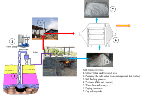
As shown in Figure 1, the traditional stove is a basic arrangement of clay earth blocks with 2400*6000*800 mm, which a tunnel runs horizontally. The U-shaped stove with an opening in the front to feed the firewood fuel and another end for exhaust gas flow out. The traditional stove site is usually constructed under open shades, reducing emitted particle effects and gases on the community. As shown in Figure 1, the saline boiler is fabricated from stainless steel with 2400*6000*300 mm. The saline used in the present study is collected from the groundwater. The firewood is used simultaneously, the mass fraction of moisture content, which the firewood with an average of the moisture content of 27% to obtain the consistency power quality and moisture level. All firewood with an average low heating value of 15 MJ/kg is made into almost nearly the same size to maintain essentially similar airspace while burning in the salt stove. The firewood feeding is continuously performed until the beginning of the saline boiling, and then the salt crystals and salt flowers are formed. Details of some basic parameters involved in the present experiment are shown in Figure 1.
Figure 1. Experimental apparatus
2.2 Salt incubator used in the study
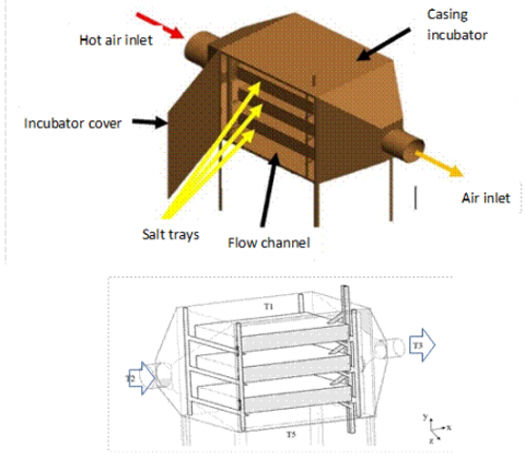
In the heat recovery process, the salt incubator has been designed and fabricated from an iron sheet (5 mm thickness) with a dimension of 71×91×83 cm. There are three compartments for salt trays fabricated from an aluminum sheet with a 51×71×12 cm dimension, as shown in Figure 2. The exhaust air is extracted from the salt boiling process and is forced into the salt incubator at the inlet port with a dimension of 25 cm and flows through three compartments of the salt tray for transferring into the wet salt inside the salt tray (indirect heat transfer) and then flows out the salt incubator at the outlet port with a dimension of 20 cm.
Five T-type thermocouples are placed inside the salt incubator at different positions to measure the hot gas temperature inside the incubator (Accuracy of 0.1% of full scale). They are pre-calibrated with the standard temperature calibrator (Dry box type). A DT85 data taker with a 30-channels is used to record the relevant parameter values. The differential pressure transducer (YOKOKAWA) is applied for the measured pressure drop across the test section. An Aeroflex tube with a thickness of 10 mm is an insulator and wrapped around the salt incubator. As the system reaches the steady-state condition, the data acquisition system collects the data mentioned above and then transmits it to the computer.
Figure 2. The developed salt incubator configuration
2.3 Experimental method
As shown in Figure 1, the salt boiling production process is performed with the conventional stove configurations, maintaining the initial relevant parameters in the same values. Before the experiment started, the initial relevant parameters were measured (4.32 m3 with an initial salty level of 20%). The saline is filled in the saline boiler, and the firewood is charged at the fire set area and ignited, and then the hot gas flows distribution into the stove tunnel under the salt boiler. The operators must scoop out the saline impurities during the boiling process to obtain the salt crystals and flowers without impurities. In general, the saline has been boiled for 12.5 hours for each saline boiling batch until the salt crystals and salt flowers are formed. The saline inside the boiler must be stirred with the paddle every 10 minutes during the boiling process. The salt flowers are first started and floated on the saline surface, while the salt crystals are later formed and sink at the bottom boiler. Therefore, the salt flowers are first ladled by the boiler paddle for drying with the open sun, and then the salt crystals ladle later. However, this method consumed a long time for the drying process. Therefore, the salt incubator with flue gas heat recovery process has been designed, constructed, and tested. The evaporated water of the saline is measured by observing the saline level during boiling. The temperatures at various positions, as mentioned above, are recorded with Datalogger, which is recorded at regular intervals of 30 minutes until the salt crystal and salt flowers form.
When using biomass stoves, most of the salt stove procedures are performed by an operator whose more experience with the saline boiling process for gradual feeding of the firewood and condition monitoring of the flame. In the drying salt in the incubator process, the wet crystal with three kg is filled into three compartments and inserted into the shelf in the incubator with inlet exhaust flue gas temperatures of 150℃, 250℃, and 350℃. The experiment found that the outlet exhaust gas temperature is still high enough to extract the heat from the hot gas and bake the wet salt. The details of some basic parameters involved in the present experiment are shown in Table 1.
Table 1. Details of some basic parameters involved in the present experiment
|
Details |
Ranges |
|
The traditional firewood stove dimension (mm*mm*mm) |
2400×6000×800 |
|
Initially salty level (%) |
20 |
|
The moisture content of the firewood, (%) |
27 |
|
Inlet exhaust temperature (℃) |
150, 250, 350 |
|
The heating value of the firewood, (MJ/kg) |
15 |
|
The salt incubator dimension (mm*mm*mm) |
710×910×830 |
|
The salt tray dimension, (mm*mm*mm) |
510×710×120 |
2.4 Data reduction
The energy balance of the salt incubator can be calculated from the amount of heating utility relative to the heating input from the waste heat as follows:
${{Q}_{in}}=\,\,{{Q}_{useful}}+{{Q}_{out}}+{{Q}_{loss}}$ (1)
The heat of the flue gas entering the salt incubator (Based on ambient temperature) can determine from the following:
${{Q}_{in}}=\,\,\overset{o}{\mathop{{{m}_{flue}}}}\,{{C}_{p,flue}}({{T}_{in}}-{{T}_{ambient}})$ (2)
The heat loss of the flue gas after entering the salt incubator (Based on ambient temperature) can calculate from the following:
${{Q}_{out}}=\,\,\overset{o}{\mathop{{{m}_{flue}}}}\,{{C}_{p,flue}}({{T}_{out}}-{{T}_{ambient}})$ (3)
The heat loss by convection term through the incubator wall determine from:
${{Q}_{loss}}=\,\,h{{A}_{wall}}\left( {{T}_{wall}}-{{T}_{ambient}} \right)$ (4)
The heat utility calculates from:
${{Q}_{useful}}=\,\,\left\{ {{\left[ m{{C}_{p}}\left( {{T}_{ini}}-{{T}_{final}} \right) \right]}_{salt\,crystal}}+{{\left[ \begin{align} & {{m}_{ini}}{{C}_{p}}\left( {{T}_{evaporate}}-{{T}_{ini}} \right)+\left( {{m}_{ini}}-{{m}_{final}} \right)L \\ & +\left( {{m}_{ini}}-{{m}_{final}} \right){{C}_{p}}\left( {{T}_{final}}-{{T}_{evaporate}} \right) \\\end{align} \right]}_{water}} \right\}\Delta t$ (5)
The thermal efficiency of the salt incubator calculates from:
$Thermal\,\,efficiency=\,\,\eta =\frac{{{Q}_{useful}}}{{{Q}_{in}}}\times 100$ (6)
Table 2 shows the accuracy and uncertainty of instruments. In the present work, the thermal efficiency of the salt incubator depends on the relevant parameters, as shown in Eq. (6). The uncertainties of experimental data are determined with the maximum uncertainties of relevant parameters of ±7.5% for the thermal efficiency (More details see in Coleman and Steel method [31]). The accuracy and uncertainty of instruments are shown in Table 2. In the present study, the thermal efficiency of the stove depends on the relevant parameters, as shown in Eq. (6). The uncertainty of the thermal efficiency can be determined.
Uncertainty of η=$=\,\,\sqrt{{{\left\{ \,+{{\left[ \begin{align} & {{\left( \frac{\partial \eta }{\partial {{m}_{flue}}}\Delta {{m}_{flue}} \right)}^{2}}+{{\left( \frac{\partial \eta }{\partial {{T}_{in}}}\Delta {{T}_{in}} \right)}^{2}}+{{\left( \frac{\partial \eta }{\partial {{T}_{ambient}}}\Delta {{T}_{ambient}} \right)}^{2}} \\ & +{{\left( \frac{\partial \eta }{\partial {{T}_{out}}}\Delta {{T}_{out}} \right)}^{2}}+{{\left( \frac{\partial \eta }{\partial {{A}_{wall}}}\Delta {{A}_{wall}} \right)}^{2}}+{{\left( \frac{\partial \eta }{\partial {{T}_{wall}}}\Delta {{T}_{wall}} \right)}^{2}} \\\end{align} \right]}_{{}}} \right\}}_{{}}}}$ (7)
Table 2. Uncertainty and accuracy of instruments used in the present study
|
Instrument |
Accuracy (%) |
Uncertainly |
|
Anemometer, m/s |
0.1 |
±0.2 |
|
Hygrometer |
0.5 |
±0.5 |
|
Thermocouple type-T |
0.1 |
±0.1 |
|
Data logger (℃) |
0.1 |
±0.2 |
|
Digital weighing scale, kg |
0.1 |
±0.2. |
3.1 Main governing equation
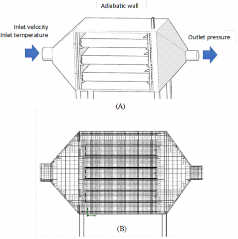
As shown in Figure 2, a numerical model of the case study is performed with dimensions. A 3D turbulent flow model predicts the temperature and flow characteristics of hot air inside the system. Based on the measured data, the initial and boundary conditions of the analysis are done, as shown in Figure 3(A), with the following assumptions:
- Single-phase steady and turbulent flow;
- Adiabatic on the incubator walls;
- Constant properties of exhaust gas.
A 3D model is designed and constructed based on a real salt incubator with three compartments. The k-e standard turbulence model is used to simulate with the main governing equations [32, 33] as
Continuity equation:
$\frac{\partial \rho }{\partial t}+div\left( \rho U \right)=0$ (8)
Momentum equation:
x-momentum:
$\rho \frac{Du}{Dt}=-\frac{\partial p}{\partial x}+div\left( \mu \,grad\,u \right)+{{S}_{{{M}_{x}}}}$ (9)
y-momentum:
$\rho \frac{Dv}{Dt}=-\frac{\partial p}{\partial y}+div\left( \mu \,grad\,v \right)+{{S}_{{{M}_{y}}}}$ (10)
z-momentum:
$\rho \frac{Dw}{Dt}=-\frac{\partial p}{\partial z}+div\left( \mu \,grad\,w \right)+{{S}_{{{M}_{z}}}}$ (11)
Energy equation:
$\rho \frac{DT}{Dt}=-p\,div\,U\,+div\left( \Gamma \,grad\,T \right)+\Phi +{{S}_{i}}$ (12)
Turbulent kinetic energy (k) equation:
$\frac{\partial \left( \rho k \right)}{\partial t}+div\left( \rho kU \right)=\,\,\,div\left[ \left( \frac{{{\mu }_{t}}}{{{\sigma }_{k}}}grad\,k \right) \right]+2{{\mu }_{t}}{{E}_{ij}}\cdot {{E}_{ij}}-\rho \varepsilon $ (13)
Turbulent kinetic energy dissipation (e) equation:
$\frac{\partial \left( \rho \varepsilon \right)}{\partial t}+div\left( \rho \varepsilon U \right)=\,\,\,div\left( \frac{{{\mu }_{t}}}{{{\sigma }_{\varepsilon }}}grad\,\varepsilon \right)+{{C}_{1\varepsilon }}\frac{\varepsilon }{k}2{{\mu }_{t}}{{E}_{ij}}\cdot {{E}_{ij}}-{{C}_{2\varepsilon }}\rho \frac{{{\varepsilon }^{2}}}{k}$ (14)
The constants for the turbulence model are obtained from Launder and Spalding [33]:
${{C}_{\mu }}=0.09$, ${{C}_{\varepsilon 1}}\,\,=\,\,1.47$, ${{C}_{\varepsilon 2}}\,\,=\,\,1.92$ , ${{\sigma }_{k}}\,\,=\,\,1.0$, ${{\sigma }_{\varepsilon }}\,\,=\,\,1.3$ (15)
Boundary conditions:
$u\,\,=\,\,0,\,\,v\,\,=\,\,0,\,\,w\,\,=\,\,0,\,\,{{q}_{wall}}\,\,=\,\,0$ (16)
Initial conditions:
$u\,\,=\,\,{{u}_{in}},\,\,v\,\,=\,\,0,\,\,w\,\,=\,\,0,\,\,T\,\,=\,\,{{T}_{in}},\,\,k\,\,=\,\,{{k}_{in}},\,\,\varepsilon \,\,=\,\,{{\varepsilon }_{in}}$ (17)
${{k}_{in}}\,\,=\,\,\frac{3}{2}{{\left( {{u}_{in}}I \right)}^{2}},\,\,\,\,{{\varepsilon }_{in}}\,\,=\,\,C_{\mu }^{3/4}\frac{{{k}^{3/2}}}{{{L}_{e}}}$ (18)
$I\,\,=\,\,\frac{{{u}^{'}}}{u}\times 100%\,$ (19)
3.2 Numerical procedure
The commercial software ANSYS Fluent package is the solver of the problem coupling with a 3D turbulent flow model based on the control volume method, the SIMPLEC algorithm of Van Doormal and Raithby [34]. Based on the computational domains and the grid configuration of the system shown in Figure 3(A) and Figure 3(B), the wall of the salt incubator is assumed as an adiabatic wall condition, and the fluid flow is assumed to be incompressible steady flow fluid and excluded gravity effect. The constant inlet temperature of 150℃, 250℃, and 350℃ is used as an initial condition at the inlet port. A simple algorithm applies a second-order upwind scheme and a non-uniform grid system to discretize the main governing equations. The computer system used in the present study is a dual CPUs socket 2011 V.3, of 16 cores-32 threads, and the memory is 32 GB of frequency 2133 MHz.
Figure 3. (A) Computational domain and (B) grid configuration of the system
3.3 Grid independent tests
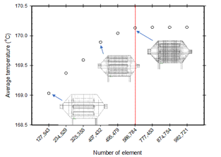
The computational grids of 127,543, 407,432, and 586,784 are done to assess the accuracy of the computation solution. As shown in Figure 4, an average air temperature of 586,784 is finer than 407,432 within 1%. There is no need to calculate at the computational grid of 586,784 and in reduce the calculation time of the numerical computation process. Therefore, the grid number of 407,432 ensures a satisfactory solution. The numerical computation process is terminated if the residual summed over all the computational nodes satisfies the criterion of 10-6.
Figure 4. The grid independence check
4.1 Predicted results verification
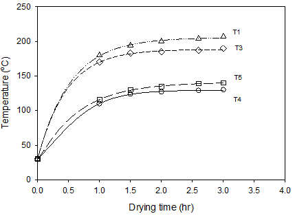
The variation of temperature distribution for different positions of the salt incubator is shown in Figure 5. In the model, the incoming exhaust gas velocity passing through all inlet ports is constant at 0.2 m/s and inlet temperatures of 150℃, 250℃, and 350℃. The predicted results obtained from the simulation are verified with the present measured data. As shown in Table 3, it can be found that reasonable agreement is obtained from the comparison and give maximum error of 5.24%, hot gas temperature.
4.2 Temperature distribution
The exhaust gas is screened the high contaminant with screen mesh before entering the salt incubator. The exhaust gas is forced into the salt incubator by an axial fan with an inlet temperature of 150℃, 250℃, and 350℃. There are three compartments for the salt crystals installed inside the salt incubator. The heat transfer from the exhaust gas to the salt crystals inside the compartments is an indirect heat transfer process inside the salt incubator—the variations of the hot gas temperatures at different positions with drying time as shown in Figure 5. In the experiment, the drying time has performed for 3 hours. For the first hour, the hot gas temperatures sharply increase and slightly increase until the 3rd hour. The maximum and minimum hot gas temperatures inside the stove occur at the upper and lower zones of the salt incubator, respectively. It is found that the main flow of the exhaust gas flows to the upper zone of the incubator and then flows out at the outlet port while the circulation at the lower zone of the incubator, as shown in Figure 6. The maximum temperature occurs at the upper zone near the inlet port and decreases slightly with the port's higher distance.
Figure 5. Variation of average air temperature inside the incubator
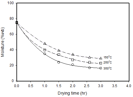
Figure 7 shows the variation of %moisture content (wet basis) with drying time for different inlet exhaust gas temperatures. The figure clearly shows that the %moisture content rapidly decreases with increasing drying time. However, this effect tends to diminish as drying time increases > 2 hours. In general, the %moisture content of the salt crystals is less than 40% wet basis. In addition, higher inlet exhaust temperature gives lower %moisture content, as shown in Figure 9.
Figure 8 shows the variation in hot gas velocity in salt incubation for different inlet exhaust gas temperatures in the top view cross-section area for the steady state condition. It can be seen that the exhaust gas flows into the incubator at the inlet port and spreads out across the incubator with uniform velocity, and then flows out at the outlet port. The maximum velocity occurs at the inlet and outlet zones, as shown in Figure 8.
Figure 6. The velocity vector and temperature distribution inside the salt incubator for inlet temperature of 150, 250, and 350℃
Figure 7. The salt drying curve
Table 3. The comparison of hot air temperatures obtained from the predicted results and the measured data
|
Inlet temperature (℃) |
Average temperature (℃) |
||||||
|
T5 |
% Error |
T1 |
% Error |
T3 |
% Error |
||
|
150 |
Sim. |
53 |
3.70 |
84 |
1.18 |
90 |
2.20 |
|
Exp. |
55 |
85 |
92 |
||||
|
250 |
Sim. |
98 |
5.24 |
152 |
1.99 |
138 |
1.44 |
|
Exp. |
93 |
149 |
140 |
||||
|
350 |
Sim. |
129 |
3.95 |
198 |
1.53 |
189 |
1.06 |
|
Exp. |
124 |
195 |
187 |
||||
Figure 8. Air velocity vector inside the incubator of inlet temperature for the steady state condition
Figure 9. The obtained dry salts for drying time of 1, 2, and 3 hr in the incubator of 350℃
4.3 Thermal efficiency analysis
Table 4 shows the comparison thermal efficiency for different inlet exhaust gas temperatures. It can be seen that the total consumed heats are 20,478.09 W, 37,992.28 W, and 56,145.89 W for inlet temperature 150℃, 250℃, 350℃, respectively. In contrast, the utilization heat is 6,762.22 W, 13,918.41 W, and 21,368.06 W. In addition, the heat losses by flue gas flow out and heat convection from the wall incubation are also increased with increasing inlet exhaust gas temperature. However, the increasing rate of the utilization of heat tends to increase for higher inlet temperatures. Therefore, the salt incubator gives the thermal efficiency of 33.02%, 36.63%, and 38.06% for inlet temperature 150℃, 250℃, 350℃, respectively.
4.4 Economic analysis
To consider the cost-effectiveness of incorporating this process into the salt drying process, therefore, it is considered worthwhile of the economics by comparing with the conventional drying process. For the economic analysis, the land and building are not included. This salt boiling business's investment cost includes the salt incubator. In contrast, the production cost or variable cost always depends on the production capacity per year, which the production costs have the cost of saline, firewood, the drying process cost. An income includes salt crystals and salt flower costs which depend on the %moisture content. The salt incubator costs 55,000 Bath to construct. At the same time, the production costs are 255,600 Baths for both conventional salt drying and salt incubator drying. The total income from the salt incubator drying is 659,642.40 Bath/year, whereas the traditional salt drying is 353,079 Baths/year. A payback period is calculated by assuming that the manufacturer runs 15 times/month. However, it depends on the salt crystals for each year and the %moisture content in the salt crystals. The payback period of the salt incubator drying is calculated from Eq. (20). From Table 5, the payback periods are 31.44 and 10.68 months for the salt conventional salt drying and the salt incubation drying, respectively.
Payback period$=\frac{\text { Investment cost }}{\text { Profit per cycle }}=\frac{\text { Investment cost }}{\text { Income per cycle-Product cost }}$ (20)
Table 4. The thermal efficiency of the salt incubator
|
Temp (℃) |
Heat source (Qin) |
Heat utility (Quseful) |
Heat loss in flue gas (Qfluegas) |
Heat loss at wall (Qloss) |
Thermal efficiency (%) |
|
150 |
20,478.09 |
6,762.22 |
12,684.29 |
1,031.58 |
33.02% |
|
250 |
37,992.28 |
13,918.41 |
22,197.51 |
1,806.36 |
36.63% |
|
350 |
56,145.89 |
21,368.06 |
31,512.54 |
3,265.29 |
38.06% |
Table 5. Cost and payback period
|
Details |
Conventional drying process |
Incubator drying process |
Unit |
|
Investment |
0 |
55,000 |
Bath |
|
Total production cost per year |
255,600 |
255,600 |
Bath |
|
Total income per year |
353,079 |
659,624.40 |
Bath |
|
Profit per cycle (Income per cycle-Production cost) |
97,479.00 |
349,042.40 |
Bath |
|
Payback period |
31.44 |
10.68 |
Month |
For the traditional salt drying, the salt crystals drying is performed in the sun. However, this method consumed a long time for the drying process. In addition, outlet exhaust gas temperature is still high enough to extract the heat from the hot gas and bake the wet salt. Therefore, the salt incubator with flue gas heat recovery process in the salt boiling process has been designed. At the inlet exhaust temperature, 350℃ gives the lowest %moisture content and gives the thermal efficiency of 38.06%. The obtained salt crystals are also increased, which results in the price and the payback period. Due to this method consuming a short time for the drying process, the obtained salt content for each year also increases. In addition, the lower %moisture content results in a higher price. The payback periods for traditional and incubator salt drying are 31.44 and 10.68 months, respectively. However, the salt incubator is still continuously developed to obtain higher thermal efficiency and can help reduce environmental and global warming problems.
The financial is supported by the Srinakharinwirot University (SWU) for this study. Udon Thani Rajabhat University supports the tools and equipment used in this research.
|
A |
area, [m2] |
|
Cp |
specific heat, [kJ kg-1℃-1] |
|
${{C}_{1}}$ |
constant, [-] |
|
${{C}_{2}}$ |
constant, [-] |
|
${{C}_{\mu }}$ |
constant, [-] |
|
h |
heat transfer coefficient, [kW m-2 ℃-1] |
|
I |
turbulent intensity, [-] |
|
$k$ |
turbulence kinetic energy, [-] |
|
L |
latent heat, [kJ kg-1] |
|
Le |
equivalent length, [m] |
|
m |
mass, [kg] |
|
$\overset{*}{\mathop{m}}\,$ |
mass flow rate, [kg s-1] |
|
p |
pressure, [ kPa] |
|
Q |
heat transfer, [kJ] |
|
T |
temperature, [℃] |
|
t |
time, [s] |
|
u,v,w |
velocity, [m s-1] |
|
Greek symbols |
|
|
$\lambda $ |
thermal conductivity, [kWm-1℃-1] |
|
$\varepsilon $ |
turbulent energy dissipation rate, [m2s-3] |
|
$\rho $ |
density, [kgm-3] |
|
${{\mu }_{l}}$ |
laminar viscosity, [N.s m-2] |
|
${{\mu }_{t}}$ |
turbulent viscosity, [N.s m-2] |
|
${{\sigma }_{k}}$ |
constants, [-] |
|
${{\sigma }_{\varepsilon }}$ |
constants, [-] |
|
Subscripts |
|
|
am |
ambient |
|
ev |
evaporate |
|
fl |
flue |
|
fi |
final |
|
ini |
initial |
|
in |
inlet |
|
lo |
loss |
|
o |
outlet |
|
us |
useful |
|
wa |
wall |
[1] Julklang, W., Golman, B. (2015). Effect of process parameters on the energy performance of spray drying with exhaust air heat recovery for production of high-value particles. Applied Energy, 151: 285-295. https://doi.org/10.1016/j.apenergy.2015.04.069
[2] Ai, S., Wang, B., Li, X., Shi, W. (2016). Analysis of a heat recovery system of the spray-drying process in a soy, protein powder plant. Applied Thermal Engineering, 103: 1022-1030. https://doi.org/10.1016/j.applthermaleng.2016.04.108
[3] Patel, S.K., Bade, M.H. (2019). Energy analysis and heat recovery opportunities in spray dryers applied for effluent management. Energy Conversion and Management, 186: 597-609. https://doi.org/10.1016/j.enconman.2019.02.065
[4] Patel, S.K., Bade, M.H. (2020). Energy targeting and process integration of spray dryer with heat recovery systems. Energy Conversion and Management, 221: 13148. https://doi.org/10.1016/j.enconman.2020.113148
[5] Liao, C.H., Horng, R.F. (2017). Experimental study of syngas production from methane dry reforming with heat recovery strategy. International Journal of Hydrogen Energy, 42: 25213-25224. https://doi/10.1016/j.ijhydene.2017.01.238
[6] Jian, Q., Luo, L. (2018). The improvement on efficiency and drying performance of a domestic venting tumble clothes dryer by using a heat pipe heat recovery heat exchanger. Applied Thermal Engineering, 136: 560-567. https://doi/10.1016/j.applthermaleng.2018.03.029
[7] Jouhara, H., Bertrand, D., Axcell, B., Montorsi, L., Venturelli, M., Almahmoud, S., Milani, M., Ahmad, L., Chauhan, A. (2021). Investigation on a full-scale heat pipe heat exchanger in the ceramics industry for waste heat recovery. Energy, 223: 120037. https://doi.org/10.1016/j.energy.2021.120037
[8] Venturelli, M., Brough, D., Milani, M., Montorsi, L., Jouhara, H. (2021). Comprehensive numerical model for the analysis of potential heat recovery solutions in a ceramic industry. International Journal of Thermofluids, 10: 100080. https://doi.org/10.1016/j.ijft.2021.100080
[9] Yan, M., Ma, C., Shen, Q., Song, Z., Chang, J. (2019). A novel lignite pre-drying system integrated with flue gas waste heat recovery at lignite-fired power plants. Applied Thermal Engineering, 150: 200-209. https://doi.org/10.1016/j.applthermaleng.2018.12.173
[10] Han, Y., Sun, Y., Wu, J. (2020). An efficient solar/lignite hybrid power generation system based on solar driven waste heat recovery and energy cascade utilization in lignite pre-drying. Energy Conversion and Management, 205: 112406. https://doi.org/10.1016/j.enconman.2019.112406
[11] Chen, Z., You, C., Wang, H., Xie, N. (2020). A novel technical route based on wet flue gas desulfurization process for flue gas dehumidification, water and heat recovery. Applied Thermal Engineering, 171: 115102. https://doi.org/10.1016/j.applthermaleng.2020.115102
[12] Zhang, Q., Niu, Y., Yang, X., Sun, D., Xiao, X., Shen, Q., Wang, G. (2020). Experimental study of flue gas condensing heat recovery synergized with low NOx emission system. Applied Energy, 269: 115091. https://doi/ 10.1016/J.APENERGY.2020.115091
[13] Xiao, L., Yang, M., Yuan, W.Z., Huang, S.M. (2021). Macroporous ceramic membrane condenser for water and heat recovery from flue gas. Applied Thermal Engineering, 186: 116512. https://doi.org/10.1016/j.applthermaleng.2020.116512
[14] Zuberi, M.J.S., Olsen, D., Liem, P., Wellig, B., Patel, M.K. (2020). Heat integration of a multi-product batch process by means of direct and indirect heat recovery using thermal energy storage. Applied Thermal Engineering, 167: 114796. https://doi.org/10.1016/j.applthermaleng.2019.114796
[15] Li, T., Li, C., Li, B., Li, C., Fang, Z., Zeng, Z. (2020). Wenyan Ou1, Juanying Huang, Characteristic analysis of heat loss in multistage counter-flow paddy, drying process. Energy Reports, 6: 2153-2166. https://doi.org/10.1016/j.egyr.2020.08.006
[16] Onyeocha, E.I., Nwaigwe, K.N., Ogueke, N.V., Anyanwu, E.E. (2020). Design and construction of an integrated tetrafluoroethane (R134a) refrigerator-waste heat recovery dryer for fabric drying in tropical regions. Heliyon, 6: e04838. https://doi.org/10.1016/j.heliyon.2020.e04838
[17] El-Shafie, M., Bassiouny, M.K., Kambara, S., El-Behery, S.M., Hussien, A.A. (2021). Design of a heat recovery unit using exhaust gases for energy savings in an absorption air conditioning unit. Applied Thermal Engineering, 194: 117031. https://doi.org/10.1016/j.applthermaleng.2021.117031
[18] Fierro, J.J., Atehortua, A.E., Londono, C.N., Giraldo, M., Jouhara, H., Wrobel, L.C. (2020). Evaluation of waste heat recovery technologies for the cement industry. International Journal of Thermofluids, 7-8: 100040. https://doi.org/10.1016/j.ijft.2020.100040
[19] Horta, G.R.C., Júnior, E.P.B., Moreira, L.F., Arrieta, F.R.P., Oliveira, R.N. (2021). Comparison of Kalina cycles for heat recovery application in cement industry. Applied Thermal Engineering, 195: 117167. https://doi.org/10.1016/j.applthermaleng.2021.117167
[20] Ye, S., Xue, B., Meng, X., Wei, X., Nakaso, K., Fukai, J. (2020). Experimental study of heat and mass recovery on steam generation in an adsorption heat pump with composite zeolite-CaCl2. Sustainable Cities and Society, 52: 101808. https://doi.org/10.1016/j.scs.2019.101808
[21] Chen, L., Wang, W., Kong, Y., Yang, L., Du, X. (2020). Hot air extraction to improve aerodynamic and heat transfer performances of natural draft dry cooling system. International Journal of Heat and Mass Transfer, 163: 120476. https://doi.org/10.1016/j.ijheatmasstransfer.2020.120476
[22] Wang, Y., Shen, C., Sun, P., Li, C., Zhang, C. (2020). Utilization of waste heat from commercial kitchen exhaust for water heating and dish drying. Journal of Building Engineering, 32: 101788. https://doi.org/10.1016/j.jobe.2020.101788
[23] Wang, L., Zhang, Y., Ke, H., Long, Y. (2021). Experimental investigation on granulation characteristics and waste heat recovery of molten slag in gas quenching dry granulation technique. Applied Thermal Engineering, 184: 116295. https://doi/10.1016/j.applthermaleng.2020.116295
[24] Shahzad, M.K., Ding, L., Xuan, Y., Gao, N., Chen, G. (2021). Energy efficiency analysis of a multifunctional hybrid open absorption system for dehumidification, heating, and cooling: An industrial waste heat recovery application. Energy Conversion and Management, 243: 114356. https://doi.org/10.1016/j.enconman.2021.114356
[25] Othman, A., Almomani, F., Al-musleh, E.I., Bouabidi, Z., Katebah, M.A., Hussein, M.M. (2021). Heat recovery in an actual LNG supply chain: Retrofitting of designed heat exchange networks (HENs) for potential fuel saving. Chemical Engineering & Processing: Process Intensification, 166: 108477. https://doi.org/10.1016/j.cep.2021.108477
[26] Golzar, F., Silveira, S. (2021). Impact of wastewater heat recovery in buildings on the performance of centralized energy recovery – A case study of Stockholm. Applied Energy, 297: 117141. https://doi.org/10.1016/j.apenergy.2021.117141
[27] Ghalavand, A., Hatamipour, M.S., Ghalavand, Y. (2021). Performance evaluation of a multi-stage humidification compression with heat recovery based on mathematical modeling. Desalination, 515: 115189. https://doi.org/10.1016/j.desal.2021.115189
[28] Baroutaji, A., Arjunan, A., Ramadan, M., Robinson, J., Alaswa, A., Abdelkareem, M.A., Olabi, A.G. (2021). Advancements and prospects of thermal management and waste heat recovery of PEMFC. International Journal of Thermofluids, 9: 100064. https://doi.org/10.1016/j.ijft.2021.100064
[29] Malesani, R., Pivato, A., Bocchi, S., Lavagnolo, M.C., Muraro, S., Schievano, A. (2021). Compost Heat Recovery Systems: An alternative to produce renewable heat and promoting ecosystem services. Environmental Challenges, 4: 100131. https://doi.org/10.1016/j.envc.2021.100131
[30] Zhang, C., Zhao, Y., Shi, X., Huang, X. (2020). Characterization of a new total heat recovery system using CaCl2 as working fluid: Thermal modeling and physical analysis. Energy and Built Environment. https://doi/ 10.1016/j.enbenv.2020.12.003
[31] Versteeg, H.K., Malalasekera, W. (1995). An Introduction to Computational Fluid Dynamics: The Finite Volume Method. Longman, New York.
[32] Launder, B.E., Spalding D.B. (1973). Mathematical Models of Turbulence. Academic Press.
[33] Van Doormal, J.P., Raithby, G.D. (1984). Enhancements of the SIMPLEC method for predicting incompressible fluid flows. Numerical Heat Transfer, 7: 147-163.
[34] Coleman, H.W., Steele, W.G. (1989). Experimental and Uncertainty Analysis for Engineers. John Wiley & Sons, New York.