Zuryati Djafar* | Andi Zahirah Salsabila | Wahyu H. Piarah
© 2021 IIETA. This article is published by IIETA and is licensed under the CC BY 4.0 license (http://creativecommons.org/licenses/by/4.0/).
OPEN ACCESS
Solar energy can be converted into electrical energy using photovoltaic (PV) and thermoelectric generators (TEG). In order to increase the effectiveness of energy absorption, a hot mirror or cold mirror spectrum separator is used. In this study, a simulation was carried out to see the effect of the cold mirror and hot mirror spectrum separator on the performance of the PV-TEG hybrid. Simulations are carried out using the LabVIEW program. The standard for the solar radiation spectrum used is AM1.5D. The incoming radiation is transmitted using a Fresnel lens to make it more focused and then transmitted to a cold mirror or hot mirror, where the spectral irradiance will be halved. Spectral irradiance with a wavelength of 400-690 nm will be directed to PV and a wavelength of 710-1150 nm will be directed to TEG. From the PV-TEG hybrid modeling and simulation using the LabVIEW program, the resulting power and efficiency are 240.635 W/m2 and 27% respectively for cold mirror and 228.835 W/m2 and 25.76% for hot mirror.
cold mirror, hot mirror, light spectrum, output power, photovoltaic, thermoelectric generator
Solar energy is the energy that is abundant, continuous, and environmentally friendly because it does not produce harmful carbon emissions like burning fossil fuels. Solar energy is included in the renewable energy group.
Regarding on the statement above, numerous researches on the development of renewable energy have been conducted, one of which is the development of the use of solar energy. The history of human civilization records that solar energy has greatly influenced all aspects of human life and the environment since the beginning of life in this world [1].
The rate of energy emitted by the sun arriving in the atmosphere is 1386 W/m2, and those arriving on the earth's surface can reach 1000 W/m2 in clear weather conditions. This is due to the influence of the earth's rotation on its axis, the earth's circulation on its trajectory and the gases in space [2].
The main problem in the utilization of solar energy is the day and night factor which always alternates so that the continuity of solar energy acquisition is always cut off at night. However, besides being able to be used directly during the day with the aid of an energy conversion device, it can also be stored in the battery for use at night [1].
As explained previously, solar energy can be converted into electrical energy using energy converters such as solar cells or photovoltaic (PV) cells. The results of the research according to Makki et al. [3] showed that PV can absorb up to 80% of solar radiation, but not all of it can be converted into electrical energy but become heat waste which can increase cell temperature that can cause a decrease in PV efficiency.
Research on PV cooling techniques to maintain temperature stability by utilizing heat waste has been carried out using gas and liquid fluids [4-6] and the use of thermoelectric coolant (TEC) [7].
In addition to the thermoelectric coolant (TEC), there is also a thermoelectric generator (TEG) which is a power generating device the resulted from the temperature difference between the two sides of the TEG. The research advancement by stacking up PV and TEG to increase the output power and increase the efficiency has been conducted by Chang et al. [8].
Research on the combination of photovoltaic and thermoelectric generators known as PV-TEG has been carried out by several researchers [9-15] with various configurations where each PV and TEG receive direct sunlight.
Another further development model of the PV-TEG hybrid is to separate the spectrum of infrared (IR) light, ultraviolet (UV) light, and visible (VL) light from the sun [16-21] which is known as a beam splitter. This development was carried out because it wanted to produce maximum performance of PV and TEG.
Hariyanto et al. [22] have conducted research on simulating PV-TEG hybrid with beam splitter hot mirrors using the standard AM1.5D solar spectrum and a hot mirror, where wavelengths 400-690 nm are transmitted to PV and 690-1150 nm are reflected to them. TEG. The result is a maximum total power of 0.554 W with an efficiency of 67.25%. Another research on simulated PV-TEG hybrid with beam splitter hot and cold mirrors using low intensity have been conducted by Piarah et al [23] using AM1.5G solar spectrum at variations of 0.05, 0.1, 0.25, 0.50 and 0.7 Sun. The light spectrum is concentrated using a Fresnel lens and then transmitted to a spectrum separator (hot and cold mirrors). The simulation results showed that by using cold mirror, the maximum total power is better than hot mirror.
Matlab Software was used in previous simulations by Hariyanto et al. [22] and Piarah et al. [23]. The Matlab software uses a high-level programming language so it requires more knowledge to operate it. Apart from Matlab software, there is also LabVIEW software. LabVIEW software is a programming software produced by National Instruments with a different concept. Like other programming languages, namely C ++, Matlab or Visual Basic, LabVIEW also has the same function and role, the difference is that LabVIEW uses a graphical or block diagram-based programming language while other programming languages use a text base. LabVIEW program is known as VI or Virtual Instruments because its appearance and operation is similar to an instrument [24]. In this article, the authors use LabVIEW software to compare the performance of using beam splitter hot and cold mirrors on PV-TEG hybrid with AM1.5D solar spectrum.
This research was conducted to compare the simulation results using LabVIEW software when using beam splitter hot and cold mirrors on PV-TEG hybrid with AM1.5D solar spectrum. The incoming light is concentrated by the Fresnel lens to be directed to the hot mirror or cold mirror. Then the hot mirror or cold mirror will separate the visible light wave spectrum (VL) on the one hand and infrared (IR) on the other. The light waves that have been separated will be forwarded to the PV and TEG modules respectively. This research begins by identifying the input parameters, then analyzing a mathematical model to determine the output. The input-output simulation is carried out in LabVIEW by first making a block diagram for the calculation of each input parameter. The results of the simulation are in the form of graphs and data that describe the characteristics of PV and TEG in various temperature.
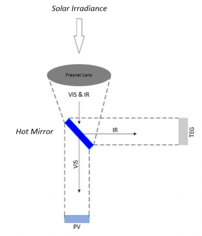
The different configurations of using hot mirror and cold mirror beam splitters in the hybrid PV-TEG scheme can be seen in Figure 1 and Figure 2 below:
Figure 1. Schematic of PV-TEG hybrid using beam splitter hot mirror
Figure 2. Schematic of PV-TEG hybrid using beam splitter cold mirror
When using hot mirror, the reflected light is directed to the TEG and the transmitted rays are directed to the PV. As for the cold mirror, the reflected light is directed to PV and the transmitted light is directed to TEG.
2.1 Photovoltaic model (PV)
The PV cell module used is a single diode PV cell with the type of Amorphous Silicon (a-Si). PV modeling is depicted with a series of equivalents as shown in Figure 3.
Figure 3. PV Single diode equivalent circuit [25]
The image above is then expressed in the following equations [26]:
$I_{p v}=I_{p h}-I_{s}-I_{r s}$ (1)
$I_{p h}=\left[I_{s c}+K_{i}\left(T-T_{o}\right)\right]\left(\frac{G}{G_{o}}\right)$ (2)
$I_{r s}=I_{s c r}\left[\exp \left(\frac{q V_{o c}}{N_{s} k A T}\right)-1\right]$ (3)
$I_{s}=I_{r s}\left(\frac{T}{T_{o}}\right)^{3} \exp \left[\frac{q E_{g}}{A k}\left(\frac{1}{T_{o}}-\frac{1}{T}\right)\right]$ (4)
and the following Eqns. (5) and (6) [27]:
$I_{p v}=I_{p h}-I_{s} \exp \left[\frac{q\left(V_{v p}+I_{p v} R_{S}\right)}{k A T}\right]$ (5)
$I_{p v}=I_{p h}-I_{s} \exp \left[\frac{q V_{v p}}{k A T}\right]-\frac{V_{v p}}{R_{S H}}$ (6)
Also Zainal and Yusuf [26] obtained the following Eq. (7):
$I_{p v}=N_{p} * I_{p h}-N_{p} * I_{s}\left[\exp \left(\frac{q V_{v p}+I_{p v} R_{S}}{N_{s} k A T}\right)-1\right]-\frac{V_{v p}+I_{p v} R_{S}}{R_{S H}}$ (7)
$I_{p v}$ is the PV output current, $I_{p h}$ is the generated photon current, $I_{S}$ is the diode current, $I_{r s}$ is the alternating current (resistance), $I_{S C}$ is the short circuit current, $K_{i}$ is the current conductivity (0.0023 A⁄℃), T is PV temperature, $T_{o}$ is standard temperature, G is irradiation, $G_{o}$ is standard irradiation, $I_{s c r}$ is standard short circuit current, $V_{o c}$ is open-circuit voltage, q is electron charge (1.602 × 10⁻¹⁹ C), $N_{p}$ is number of serial cells in module, $N_{p}$ is the number of parallel cells in the module, k is the Boltzman constant (1.38 × 10⁻²³ J), A is the ideal diode factor (for amorphous silicon = 1), $E_{g}$ is the band gap energy, $R_{S}$ is the series resistance and $R_{S H}$ is parallel resistance.
PV performance is calculated by the equation [28]:
$P_{i n}=G A_{\rho v}$ (8)
$F F=\frac{I_{M P} V_{M P}}{I_{S C}\quad V_{O C}}$ (9)
$P_{o u t}=V_{o c} I_{s c} F F$ (10)
$\eta_{\rho v}=\frac{I_{M P} V_{M P}}{G A_{\rho v}}$ (11)
$P_{\text {in }}$ is the PV input power, $P_{\text {out }}$ is the PV output power, FF is the correction factor, $\eta_{\rho v}$ is the PV efficiency. $I_{M P}$ is the current at the point of maximum power, $V_{M P}$ is the voltage at the point of maximum power, G is the irradiation and $A_{\rho v}$ is the surface area. The specific values of the parameters used are: $\mathrm{G}=1 \mathrm{Sun}=317.4374 \mathrm{~W} / \mathrm{m}^{2}, A_{\rho v}$= 0.0025 m2. The $V_{M P}$ value is obtained from the calculation results in equation (7), the $V_{M P}$ value is varied from 0 to 2.5 Volts, and the value of $V_{o c}$= 2.4 Volts and the value of $I_{S C}$= 0.89769 A is obtained from the PV specifications used.
Eqns. (1) - (11) are inputted into LabVIEW to make block diagram calculations and input/output relationships as in Figure 4. The results are displayed on the front panel as in Figure 5. In this model the TEG functions in dynamic conditions, because in practice the TEG input temperature fluctuates greatly over time. The analysis used to determine current, voltage and power is to create an equivalent scheme similar to PV (see Figure 6) by considering the Seebeck effect.
Figure 4. Block diagram of (1) - (11) equations
Figure 5. Front panel of PV simulation
Figure 6. Schematic of the internal TEG resistance at maximum power [29]
The TEG used is the SP1848-27145 SA type where the analysis at steady-state conditions is carried out to verify the TEG electrical parameters that are in the module specifications. The heat absorbed by the $Q_{H}$ hot side is expressed by the equation [29]:
$Q_{H}=\alpha I T_{H}+K\left(T_{H}-T_{C}\right)-0.5 R I^{2}$ (12)
$K=\frac{k A_{T E G}}{t}$ (13)
$T_{H}$ is the hot side temperature, $T_{C}$ is the cold side temperature, I is the TEG current, $\alpha$ is the Seebeck coefficient, R is the internal resistance, k is thermal conductivity, $A_{T E G}$ is the surface area of TEG and t is the thickness of TEG. The calculation of the current-voltage TEG is stated with the following equations [29]:
$V_{o c}=\alpha \Delta \mathrm{T}$ (14)
$I_{T E G}=\frac{\alpha \Delta \mathrm{T}}{R_{T E G}+R_{\text {Load }}}$ (15)
$V_{T E G}=\frac{\alpha \Delta \mathrm{T}}{R_{T E G}+R_{L o a d}} \cdot R_{L o a d}$ (16)
$P_{T E G}=\frac{(\alpha \Delta \mathrm{T})^{2} \cdot R_{\text {Load }}}{\left(R_{T E G}+R_{\text {Load }}\right)^{2}}$ (17)
$P_{T E G}=\frac{\left(V_{O C}\right)^{2}}{4 R_{T E G}}$ (18)
$\eta_{T E G}=\frac{V_{T E G} I_{T E G}}{Q_{H}}$ (19)
$V_{o c}$ is the open-circuit voltage, $I_{T E G}$ is the TEG output current, $V_{T E G}$ is the TEG voltage, $P_{T E G}$ is the TEG output power, $\alpha$ is the Seebeck coefficient of the semiconductor material, $\eta_{T E G}$ is the efficiency, $R_{T E G}$ is the internal resistance of the TEG, and $R_{\text {Load }}$ is the external resistance. Eqns. (12) - (19) are entered into LabVIEW to make a block diagram for the calculation of input/output as in Figure 7. The results are displayed on the front panel as shown in Figure 8.
3.1 Comparison of PV simulation results
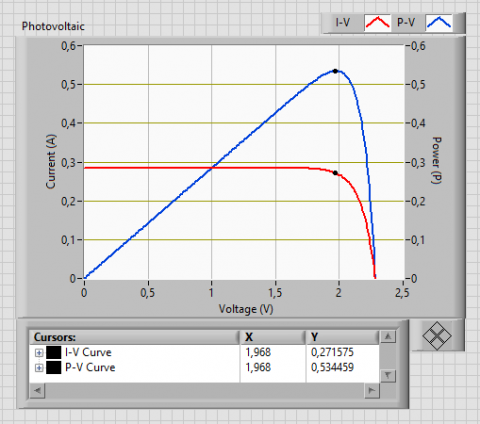
As a comparative parameter, a current curve I with a voltage V and a power curve P with a voltage V are used. The characteristics of the curve obtained are identical to those obtained by Schweber [30] and Piarah et al. [23]. In Piarah et al, using a low intensity of 0.05 Sun produced 0.01976 W of power for cold mirror and 0.01867 W for hot mirror.
(a)
(b)
Figure 9. Simulation results of I-V Curves and P-V Curves on Photovoltaics (a) Cold mirror (b) Hot mirror
Figure 9 shows the simulation results of the I-V curve and the P-V curve using cold and hot mirrors, respectively. The power and efficiency produced by using a beam splitter cold mirror is 0.534 W and 67.339% while using a beam splitter hot mirror the resulting power and efficiency are 0.5049 W and 67.156% respectively.
3.2 Comparison of TEG simulation results
Figure 10 shows a comparison of the TEG simulation results using the respective beam splitter cold and hot mirrors. Showed to have similar power output characteristic with a maximum power of 0.043 W but different efficiency (further explain in 3.3).
(a)
(b)
Figure 10. Simulation results of TEG (a) Cold mirror (b) Hot mirror
3.3 Comparison of PV temperature change models
(a)
(b)
Figure 11. Curve of temperature change I-V (a) Cold mirror (b) Hot mirror
(a)
(b)
Figure 12. Curve of change in temperature of P-V (a) Cold mirror (b) Hot mirror
Figures 11 and 12 show the comparison of the simulation results of the I-V curve and the P-V curve with the temperature change input (25, 26, 27, 28, and 29℃) and the intensity input for the cold mirror beam splitter is 317.4374 W/m2 while the hot mirror is 300.7302 W/m2.
There are differences that is resulted from each beam splitter used where the maximum power for the cold mirror is 0.65441 W and for the hot mirror is 0.618196 W. Further detail for the use of cold mirror can be seen in Table 1, while beam splitter hot mirror in Table 2.
Table 1. Cold mirror
|
Temperature (℃) |
Isc (A) |
Voc (V) |
Imp (A) |
Vmp (V) |
Pmp (W) |
|
25 |
0,2850 |
2,2820 |
0,2716 |
1,9680 |
0,5345 |
|
26 |
0,3056 |
2,2574 |
0,2912 |
1,9440 |
0,5660 |
|
27 |
0,3262 |
2,2326 |
0,3088 |
1,9320 |
0,5965 |
|
28 |
0,3469 |
2,2075 |
0,3281 |
1,908 |
0,6260 |
|
29 |
0,3675 |
2,1822 |
0,3474 |
1,884 |
0,6544 |
Table 2. Hot mirror
|
Temperature (℃) |
Isc (A) |
Voc (V) |
Imp (A) |
Vmp (V) |
Pmp (W) |
|
25 |
0,2700 |
2,2764 |
0,2566 |
1,9680 |
0,5050 |
|
26 |
0,2895 |
2,2518 |
0,2751 |
1,9440 |
0,5347 |
|
27 |
0,3091 |
2,2269 |
0,2935 |
1,9200 |
0,5635 |
|
28 |
0,3286 |
2,2018 |
0,3119 |
1,8960 |
0,5914 |
|
29 |
0,3482 |
2,1766 |
0,3302 |
1,8720 |
0,6182 |
3.4 Comparison of TEG temperature change models
(a)
(b)
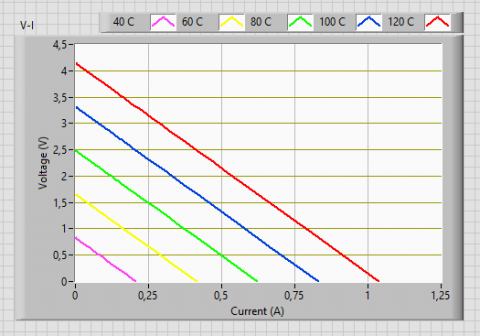
Figure 13. Temperature change curve V-I (a) Cold mirror (b) Hot mirror
(a)
(b)
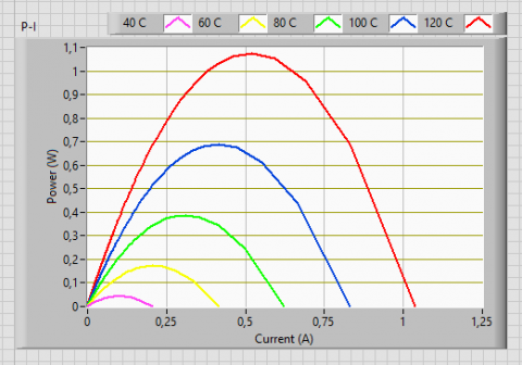
Figure 14. Curve of change in temperature of P-I (a) Cold mirror (b) Hot mirror
Figures 13 and 14 show the comparison of the simulation results of the V-I and P-I curves for TEG with changes in the temperature of the hot side Th, respectively 40, 60, 80, 100, and 120℃, and the cold side input Tc is constant at 20℃ using each beam splitter cold and hot mirrors. The results obtained are the same output power, but there are differences in the value of efficiency obtained due to differences in intensity values leading to TEG. For instance, at a temperature of 40℃, the use of a beam splitter cold mirror produces a power of 0.043 W and an efficiency of 9.8%, while using a beam splitter hot mirror the resulting power and efficiency are 0.043 W and 9.36%.
The result of PV-TEG hybrid simulation using beam splitter cold mirror and hot mirror with AM1.5D spectrum has different results. The use of cold mirror beam splitter showed more effective than hot mirror beam splitter. This is indicated by the value of the sun's intensity reflected using a cold mirror to the PV of 317.4374 W/m2 compared to a hot mirror of 300.7302 W/m2. In addition, the power and efficiency of the PV-TEG hybrid simulation using a cold mirror beam splitter is 240.635 W/m2 and is 27% greater than the hot mirror beam splitter that is 228.835 W/m2 and 25.76%.
[1] Pudjanarsa, A., Nursuhud, D. (2013). Energy Conversion Engine. ISBN: 978-979-29-0483-3. Andi. Yogyakarta. [In Bahasa].
[2] Himran, S. (2019). Solar Energy. ISBN: 978-623-01-1168-6. Andi. Yogyakarta. [In Bahasa].
[3] Makki, A., Omer, S., Sabir, H. (2015). Advancements in hybrid photovoltaic systems for enhanced solar cells performance. Renewable and Sustainable Energy Reviews, 41: 658-684. https://doi.org/10.1016/j.rser.2014.08.069
[4] Chow, T.T., He, W., Ji, J. (2006). Hybrid photovoltaic-thermosyphon water heating system for residential application. Solar Energy, 80(3): 298-306. https://doi.org/10.1016/j.solener.2005.02.003
[5] Li, M., Li, G. L., Ji, X., Yin, F., Xu, L. (2011). The performance analysis of the Trough Concentrating Solar Photovoltaic/Thermal system. Energy Conversion and Management, 52(6): 2378-2383. https://doi.org/10.1016/j.enconman.2010.12.039
[6] Huang, B.J., Lin, T.H., Hung, W.C., Sun, F.S. (2001). Performance evaluation of solar photovoltaic/thermal systems. Solar Energy, 70(5): 443-448. https://doi.org/10.1016/S0038-092X(00)00153-5
[7] Kane, A., Verma, V. (2013). Performance enhancement of building integrated photovoltaic module using thermoelectric cooling. International Journal of Renewable Energy Research, 3(2): 320-324.
[8] Chang, H., Kao, M., Cho, K., Chen, S., Chu, K., Chen, C. (2011). Integration of CuO thin fi lms and dye-sensitized solar cells for thermoelectric generators. Current Applied Physics, 11(4): S19-S22. https://doi.org/10.1016/j.cap.2010.12.039
[9] Hashim, H.T. (2011). Full-spectrum solar energy harvesting using nanotechnology enabled photovoltaic/thermoelectric hybrid system. PhD thesis, Cardiff University.
[10] Wang, N., Han, L., He, H., Park, N.-H., Koumoto K. (2011). A novel highperformance photovoltaic–thermoelectric hybrid device. Energy Environ. Sci., 4(9): 3676-3679. https://doi.org/10.1039/C1EE01646F
[11] Demak R.K., Hatib R. (2016). Comparison of solar energy with halogen lamps on the efficiency of multicrystalline photovoltaic modules. In Bahasa Indonesia: Komparasi Energi Surya dengan lampu Halogen Terhadap Efisiensi Modul Photovoltaic Tipe Multicrystalline, 7(1): 625-633.
[12] Van Sark, W.G.J. H.M. (2011). Feasibility of photovoltaic – Thermoelectric hybrid modules. Appl. Energy, 88(8): 2785-2790. https://doi.org/10.1016/j.apenergy.2011.02.008
[13] Bjørk, R., Nielsen K.K. (2015). The performance of a combined solar photovoltaic (PV) and thermoelectric generator (TEG) system. Solar Energy, 120: 187-194. https://doi.org/10.1016/j.solener.2015.07.035
[14] Wu, Y.Y., Wu, S.Y., Xiao, L. (2015). Performance analysis of photovoltaic–thermoelectric hybrid system with and without glass cover. Energy Convers. Manag., 93: 151-159. https://doi.org/10.1016/j.enconman.2015.01.013
[15] Rezania, A., Rosendahl,L. A. (2017). Feasibility and parametric evaluation of hybrid concentrated photovoltaic-thermoelectric system. Appl. Energy, 187: 380-389. https://doi.org/10.1016/j.apenergy.2016.11.064
[16] Ju, X., Wang, Z., Flamant, G., Li, P., Zhao, W. (2012). Numerical analysis and optimization of a spectrum splitting concentration photovoltaic – thermoelectric hybrid system. Solar Energy, 86(6): 1941-1954. https://doi.org/10.1016/j.solener.2012.02.024
[17] Li, Y., Witharana, S., Cao, H., Lasfargues, M., Huang, Y., Ding, Y. (2014). Wide spectrum solar energy harvesting through an integrated photovoltaic and thermoelectric system. Particuology, 15: 39-44. https://doi.org/10.1016/j.partic.2013.08.003
[18] Elsarrag, E., Pernau, H., Heuer, J., Roshan, N., Alhorr, Y., Bartholomé, K. (2015). Spectrum splitting for efficient utilization of solar radiation: A novel photovoltaic – thermoelectric power generation system. Renewables: Wind, Water, and Solar, 2: 16. https://doi.org/10.1186/s40807-015-0016-y
[19] Mustofa., Djafar, Z., Syafaruddin., Piarah, W.H. (2018). A new hybrid of photovoltaic-thermoelectric generator with hot mirror as spectrum splitter. Journal of Physical Science, 29 (Supp.2): 63-75. https://doi.org/10.21315/jps2018.29.s2.6
[20] Piarah, W.H., Djafar, Z., Syafaruddin., Mustofa. (2019). The characterization of a spectrum splitter of TechSpec AOI 50.0mm square hot and cold mirrors using a halogen light for a photovoltaic-thermoelectric generator hybrid. Energies, 12(3): 353. https://doi.org/10.3390/en12030353
[21] Mustofa, Basri, Basri, H., Mahmudi, I., Jumiyatun., Hariyanto., Djafar, Z., Piarah, W.H. (2020). Low sun spectrum on simulation of a thin film photovoltaic, heat absorber, and thermoelectric generator system. Journal of the Japan Institute of Energy, 99(8): 88-93. https://doi.org/10.3775/jie.99.88
[22] Hariyanto, H., Mustofa, M., Djafar, Z., Piarah, W.H. (2019). Mathematical modeling in combining photovoltaic and thermoelectric generator using a spectrum splitter. EPI International Journal of Engineering, 2(1): 74-79. https://doi.org/10.25042/epi-ije.022019.13
[23] Piarah, W.H., Djafar, Z., Hariyanto., Mustofa. (2019). A new simulation of photovoltaic and thermoelectric generator hybrid with a beam splitter cold and hot mirror for low intensity. International Review of Mechanical Engineering (I.RE.M.E.), 13(9): 559-567. https://doi.org/10.15866/ireme.v13i9.17884
[24] Suputra Widharma, I.G. (2020). Basic Programming and Application of LabVIEW. In Bahasa Indonesia: Dasar Pemrograman dan Penerapan LabVIEW. https://www.researchgate.net/publication/344953903, accessed on Dec. 2020.
[25] Sodiq Ja’far. (2017). Simulation Performance Photovoltaics with SnO2 Material. Physic Department, Science and Technology Faculty, State Islamic University Maulana Malik Ibrahim, Malang., Malang Indonesian.
[26] Zainal, N.A., Apen, A., Yusoff, A.R. (2016). Modelling of photovoltaic module using Matlab Simulink. IOP Conference Series: Materials Science and Engineering, 114(1): 012137. https://doi.org/10.1088/1757-899X/114/1/012137
[27] Honsber, C., Bowden, S. (2020). Equations for Photovoltaic. PVEducation. [Online]. https://www.pveducation.org/pvcdrom/appendices/standard-solarspectra.
[28] Belkassmi, Y., Rafiki, A., Gueraoui, K., Elmaimouni, L., Tata, O., Hassanain, N. (2017). Modeling and simulation of photovoltaic module based on one diode model using Matlab/Simulink. Proc. – 2017 Int. Conf. Eng. MIS, pp. 1-6. https://doi.org/10.1109/ICEMIS.2017.8272965
[29] Mawi, R., Kazuz, Y. (2014). Hybrid Solar Thermo-Electric Systems for Combined Heat and Power. PhD Thesis, Cardiff University.
[30] Schweber, B. (2020). Solar cells and power, Part 2 – power extraction. POWERELECTRONIC TIPS. [Online]. Available: https://www.powerelectronictips.com/solar-cells-power-part-2-power-extraction/.