Ali K. Abdul Razzaq* | Khudheyer S. Mushatet
© 2021 IIETA. This article is published by IIETA and is licensed under the CC BY 4.0 license (http://creativecommons.org/licenses/by/4.0/).
OPEN ACCESS
The thermal and fluid physiognomies of a double twisted tube heat exchanger was examined numerically. Twisted engineering is a wide-use method to improve heat transfer in heat exchangers. A counter-flow mode utilizing hot water in the inner tube and cold air in the outer tube was considered. This study aims to progress the thermal performance of the double tube heat exchanger by using twisted tubes instead of plane tubes. The heat exchanger was (1m) length, outer diameter (0.05m) and inner diameter (0.025m), both with a thickness (0.004m). It was tested for different values of twist ratios (Tr= 5, 10, and 15 respectively) and Reynolds numbers (Re=5000 to 30000). The Navier - Stockes and energy equations besides the turbulence model in demand for modelling this physical problem. ANSYS Fluent code was used for the numerical simulation. The results showed that the twisted tube heat exchanger showed increasing heat transfer compared with a plain tube heat exchanger. It was found that the cold outlet temperature, pressure drop and effectiveness are increased as the twist ratio increases.
twisted tubes, double tube heat exchanger, CFD, twist ratio, counter flow
Nowadays, there is an urgent need for highly intelligent and efficient heat exchangers. Various assumptions and techniques have been used to improve thermal performance and heat transfer in heat exchangers. The passive enhancement method of heat exchangers is commonly used in industries because it does not require more additional equipment or the consumed extra energy [1]. Some of the researchers have conducted studies on the twisted tube heat exchangers Any increased in the heat transfer that leads to the increasing pressure drop justifies the research in that area to evaluate the system's heat transfer and fluidic performance.
Mushatet and Hmood [2] numerically studied the effect of twist ratio on turbulent heat transfer in a twisted triangular tube heat exchangers. The results indicated that there was an increase in heat transfer in the twisted tube when compared with the regular tube. Dzyubenko et al. [3] made a twisted tube test to achieve the highest correlation between temperature and pressure drop at S / de = 6.2-34 and Re = 2000-40,000. Asmantas et al. [4] studied the heat transferred through a twisted oval tube. Their results showed improved heat transfer and flow resistance rates ranging between 20% -40% and 50% -80%, respectively. Tang et al. [5] studied heat transfer and pressure drop of twisted oval tube (TOT) and twisted tri-lobed tube (TTT) with the same twisted pitch p=200 mm. They conducted a numerical study on the effect of cross-section and twisted pitches of (TTT) on heat, and also examined the flow and heat transfer characteristics for different twisted direction. Many studies were conducted on the twisted square tube [6-9], the twisted spiral tube [10-12], and the twisted oval tube [13-16]. Many researchers have conducted extensive research on the twisted tapes, where they studied the effect of the twisted tapes inside the smooth circular tubes on the heat transfer and the pressure drop, Meyer et al. [17] made an experimental study on the characteristics of heat transfer and pressure drop in transitional regime of twisted tapes in smooth circular tubes, the experiments were conducted in circular tubes with an inner diameter of 19 mm and a length of 5.27 m and insertion of a twisted tape with ratios of 3,4,5. The experiments results showed that when the twisted ratio was varied and the heat flux was constant, the heat flux increased the time required to transfer from the laminar to the transitional flow. It was also found that the friction factors increase as the twist ratio decreases. In contrast, when the twist ratio and Reynolds number remain constant, an increase in the heat flux decreased the friction coefficient. While Sivakumar et al. [18] conducted experimental was carried for measuring heat transfer, friction factor and Reynolds number in a concentric tube containing a twist tape. The different twist ratio y = 2.52, 3.00 and 3.20 had been studied. The results showed that the twisted tape is accessible high heat transfer by friction factor increases. Whereas, Ponnada et al. [19], conducted an experimental study with a sophisticated technology using a heat pipe that works as a heat transfer device that works within Reynolds number 3000-16000. The heat transfer enhancement, friction factor and thermal performance of water in ordinary tube are compared with twisted tapes, perforated twisted tapes and alternate axis perforated twisted tapes in round tubes. Mushatet et al. [20] studied experimentally and numerically the effect of new tapered configuration of twisted tape in a heated tubes on a thermal and hydrodynamic characteristic. The experimental and numerical results revealed that the Nusselt number increased significantly by 75% and 100% respectively, and the friction factor increased by 220% and 226%, respectively. While the experimental and numerical thermal performance factor increases by 1.19 and 1.37, respectively. Mushatet and Youssif [21] studied numerically effect flow a nanofluid in a circular tube equipped with a double twisted tape. The results found that the heat transfer improves with the double twisted compared with the single twisted with increased volume concentration. Whereas, a counter clockwise twisting tape offered better thermal performance than clockwise twisting. In addition, the Nusselt number and the friction factor increased with the decrease in twist ratio decreases. Khudheyer and Farah [22] investigated numerically the impact of a double twisted tape in a circular tube in which a nanofluid flows. The Reynolds number ranged from 5000 to 35000, the volume concentration of 0.5% and 4%, and twisted ratio (y/w) of 2, 4, and 6. The results showed that the Nusselt number, the friction factor, and overall performance all increased with the decrease of the twisted ratio. Also, the heat transfer improved when using the double twisted tape and Al2O3/water nanofluid by 181%. While highest overall performance value of 2.25 was observed at a volume concentration of Al2O3/water is 4%, and the twisted ratio of (Tr=2).
Many researchers have made inserts on the tubes by adding twisted tapes to improve the heat transfer efficiency of the exchanger, as it is easy to assemble and disassemble these twisted tapes [23-30]. According to the aforementioned literature study, there is no study documented on twisted double tube heat exchanger. So this study focus on enhancement the performance of circular double tube heat exchanger by twisting the inner tube with different twist rations (Tr=5, 10 and 15) with a Reynolds number range of 5000-30000 under turbulent flow regimes.
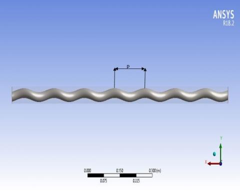
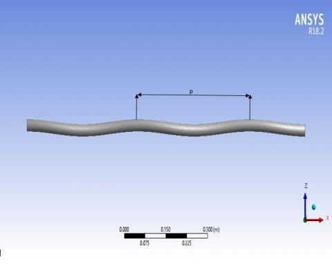
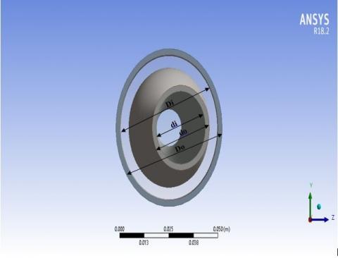
The physical model consists of the double circular twisted tube heat exchanger, as shown in Figure 1. The double circular twisted tube has a length of 1m, the inner diameter (di) of the inner pipe is 25mm, and the inner diameter (Di) of the outer pipe is 50mm, the thickness of both pipes is 2mm and three values of twist pitch (P=145mm, 290mm, and 435mm) were examined at different values of Reynolds number (5000-30000).
(a) double circular twisted tube
(b) circular twisted tube with Tr=5
(c) circular twisted tube with Tr=10
(d) circular twisted tube with Tr=15
(e) Front view of double circular twisted tube
Figure 1. Schematic representation for the physical problem
The governing equations for three-dimensional turbulent flow and heat transfer fields include the continuity, momentum, and energy equations, realized by the Cartesian coordinate system and described by full Navier-Stockes. All of the mentioned equations are listed as follows [2]:
3.1 Assumptions of flow
The steady-state turbulent flow assumptions were taken.
The following assumptions:
1- Steady-state flow.
2- Turbulent flow.
3- Three-dimensional flow.
4- Incompressible flow.
5- Body force is ignored.
$\frac{\partial }{\partial x}\rho u+\frac{\partial }{\partial v}+\frac{\partial }{\partial z}\rho w=0$ (1)
Momentum equations:
$\begin{aligned} \rho\left(\frac{\partial \mathrm{u}^{2}}{\partial \mathrm{x}}+\frac{\partial \mathrm{uv}}{\partial \mathrm{y}}+\frac{\partial \mathrm{uw}}{\partial \mathrm{z}}\right) & \\=&-\frac{\partial \mathrm{p}}{\partial \mathrm{x}}+\frac{\partial}{\partial \mathrm{x}}\left(2 \mu_{e f f} \frac{\partial \mathrm{u}}{\partial \mathrm{x}}\right)+\frac{\partial}{\partial \mathrm{y}}\left(\mu_{e f f} \frac{\partial \mathrm{u}}{\partial \mathrm{y}}\right) \\ &+\frac{\partial}{\partial \mathrm{z}}\left(\mu_{e f f} \frac{\partial \mathrm{u}}{\partial \mathrm{z}}\right)+\frac{\partial}{\partial \mathrm{y}}\left(\mu_{e f f} \frac{\partial \mathrm{v}}{\partial \mathrm{x}}\right) \\ &+\frac{\partial}{\partial \mathrm{z}}\left(\mu_{e f f} \frac{\partial \mathrm{w}}{\partial \mathrm{x}}\right) \end{aligned}$ (2)
Energy equations:
$\rho\left(\frac{\partial \mathrm{uv}}{\partial \mathrm{x}}+\frac{\partial \mathrm{v}^{2}}{\partial \mathrm{y}}+\frac{\partial \mathrm{v} \mathrm{w}}{\partial \mathrm{z}}\right)=-\frac{\partial \mathrm{p}}{\partial \mathrm{y}}+\frac{\partial}{\partial \mathrm{x}}\left(\mu_{e f f} \frac{\partial \mathrm{v}}{\partial \mathrm{x}}\right)+\frac{\partial}{\partial \mathrm{y}}\left(2 \mu_{e f f} \frac{\partial \mathrm{v}}{\partial \mathrm{y}}\right)+\frac{\partial}{\partial \mathrm{z}}\left(\mu_{e f f} \frac{\partial \mathrm{v}}{\partial \mathrm{z}}\right)+\frac{\partial}{\partial \mathrm{x}}\left(\mu_{e f f} \frac{\partial \mathrm{u}}{\partial \mathrm{y}}\right)+\frac{\partial}{\partial \mathrm{z}}\left(\mu_{e f f} \frac{\partial \mathrm{w}}{\partial \mathrm{y}}\right)$ (3)
$\frac{\partial \mathrm{uT}}{\partial \mathrm{x}}+\frac{\partial \mathrm{vT}}{\partial \mathrm{y}}+\frac{\partial \mathrm{wT}}{\partial \mathrm{z}}=\frac{\partial}{\partial \mathrm{x}}\left(\Gamma_{\text {eff }} \frac{\partial \mathrm{T}}{\partial \mathrm{x}}\right)+\frac{\partial}{\partial \mathrm{y}}\left(\Gamma_{\text {eff }} \frac{\partial \mathrm{T}}{\partial \mathrm{y}}\right)+\frac{\partial}{\partial \mathrm{z}}\left(\Gamma_{\text {eff }} \frac{\partial \mathrm{T}}{\partial \mathrm{z}}\right)$ (4)
$\Gamma_{e f f}=\Gamma+\Gamma_{t}$ (5)
$\mu_{e f f}=\mu+\mu_{t}$ (6)
3.2 Turbulence model
The standard k-ɛ model is used to treat the influence of turbulence on the flow. Standard k-ɛ widely used in heat transfer flow due to their feasible accuracy for a broad range of turbulent flows [29]. It was initially suggested by Launder and Spalding. Transport equations in the standard k-ɛ model are written as follows [2]:
Turbulence kinetic energy (k) equation:
$\rho\left(\frac{\partial}{\partial x}(k u)+\frac{\partial}{\partial y}(k v)+\frac{\partial}{\partial z}(k w)\right)=\frac{\partial}{\partial x}\left(\frac{\mu_{z}}{\sigma_{k}} \frac{\partial k}{\partial x}\right)+\frac{\partial}{\partial y}\left(\frac{\mu_{e} \partial k}{\sigma_{k}} \frac{\partial k}{\partial y}\right)+\frac{\partial}{\partial z}\left(\frac{\mu_{e} \partial k}{\sigma_{k}} \frac{\partial k}{\partial z}\right)+G-\rho \varepsilon$ (7)
$\rho\left(\frac{\partial}{\partial \mathrm{x}}(\varepsilon \mathrm{u})+\frac{\partial}{\partial \mathrm{y}}(\varepsilon \mathrm{v})+\frac{\partial}{\partial \mathrm{z}}(\varepsilon \mathrm{w})\right)=\frac{\partial}{\partial \mathrm{x}}\left(\frac{\mu_{\mathrm{t}}}{\sigma_{\varepsilon}} \frac{\partial \varepsilon}{\partial \mathrm{x}}\right)+\frac{\partial}{\partial \mathrm{y}}\left(\frac{\mu_{\mathrm{t}}}{\sigma_{\varepsilon}} \frac{\partial \varepsilon}{\partial \mathrm{y}}\right)+\frac{\partial}{\partial \mathrm{z}}\left(\frac{\mu_{\mathrm{t}}}{\sigma_{\varepsilon}} \frac{\partial \varepsilon}{\partial \mathrm{z}}\right)+C_{1 \varepsilon} \rho \frac{\varepsilon}{\mathrm{k}} \mathrm{G}-\mathrm{C}_{2 \varepsilon} \rho \frac{\varepsilon^{2}}{\mathrm{k}}$ (8)
where, G is referred to the generation term and is given
$\mathrm{G}=\mu_{\mathrm{t}}\left[2\left(\frac{\partial \mathrm{u}}{\partial \mathrm{x}}\right)^{2}+2\left(\frac{\partial \mathrm{v}}{\partial \mathrm{y}}\right)^{2}+2\left(\frac{\partial \mathrm{w}}{\partial \mathrm{z}}\right)^{2}+\left(\frac{\partial \mathrm{v}}{\partial \mathrm{y}} \frac{\partial \mathrm{u}}{\partial \mathrm{x}}\right)^{2}+\left(\frac{\partial \mathrm{v}}{\partial \mathrm{z}} \frac{\partial \mathrm{w}}{\partial \mathrm{x}}\right)^{2}+\left(\frac{\partial \mathrm{v}}{\partial \mathrm{z}} \frac{\partial \mathrm{w}}{\partial \mathrm{y}}\right)^{2}\right]$ (9)
Also,
$\mathrm{k}=\frac{1}{2}\left(\overline{\mathrm{u}^{\prime 2}}+\overline{\mathrm{v}^{\prime 2}}+\overline{\mathrm{w}^{\prime 2}}\right)$ (10)
$\varepsilon=\overline{\mathrm{e}_{1 j}^{\prime} \cdot \mathrm{e}_{1 j}^{\prime}}$ (11)
$\mu_{\mathrm{t}}=\rho c_{\mu} \frac{\mathbf{k}^{2}}{\varepsilon}$ (12)
where, $c \mu=0.09, c 1 \varepsilon=1.44, c 2 \varepsilon=1.92, \sigma k=1, \sigma \varepsilon=1.3$.
3.3 Numerical component
The present model's governing equations are solved numerically. The Navier-Stokes equations in three dimensions are resolved by using the CFD code Fluent 18.2 predicted the flow behavior. Fluid flow parameters may be determined at a large number of places in a twisted tube using CFD modeling. The convergence standard for momentum and energy equations is defined as 1*10-4.
3.4 Boundary conditions
The studied model was subjected to the boundary conditions as bellow:
1. at the inlets: mass-inlet and temperature-inlet is set as a boundary condition of inlets in two cases:
(a) mc is selected as (0.0827,0.1654,0.248,0.33,0.4135,0.4962) kg/s.
(b) mh is selected as (0.0984,0.1969,0.296,0.3938,0.4923,0.5908) kg/s.
(c) Tc is selected as (298) and Th is selected as (343).
2. At walls: no-slip condition, the outer wall of the outer pipe is insulated.
3. At the outlets: Relative gage pressure is assumed to be zero.
3.5 Data reduction
The logarithmic mean temperature difference (LMTD) is described as:
$\mathrm{LMTD}=\frac{\Delta \mathrm{T} 1-\Delta \mathrm{T} 2}{\ln \left(\frac{\Delta \mathrm{T} 1}{\Delta \mathrm{T} 2}\right)}$ (13)
$\Delta T 1=(T h i-T c o)$ (14)
$\Delta T 2=( Tho - Tci )$ (15)
The heat exchanger effectiveness is:
$\epsilon=\frac{\text { qact }}{q_{\max }}$ (16)
$C h=m_{h} c p_{h}$
$C \mathrm{c}=m_{c} c p_{c}$
$qact=m \mathrm{Cc}(T c o-T c i)$ (17)
$q m a x=(T h i-T c i)$ (18)
where, Cmin is the minimum value of Ch and Cc.
$\Delta P i=P h i-P h o$ (19)
$\Delta P o=P c i-P c o$ (20)
$\Delta P \mathrm{~T}=\Delta P_{\mathrm{o}}+\Delta P i$ (21)
The overall performance index is given as
$\eta=\frac{\epsilon}{\Lambda \mathbf{P T}}$ (22)
$R e=\frac{\rho \mathrm{Dh}, \mathrm{V}}{\mu}$ (23)
$D h, \mathrm{i}=d i$ (24)
${D h, \mathrm{o}}=D i-d o$ (25)
The present study investigates the heat transfer and fluid flow characteristics in the double circular twisted tube heat exchanger at different twisted ratios. The effect of changing the twist ratio lengthways the flow course on the heat transfer and flow field is deliberated by presenting the outlet temperature, pressure drop, overall performance of the heat exchanger and effectiveness of the heat exchanger.
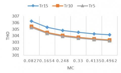
Figure 2. Variation between the outlet temperature of hot fluid and water flow rate
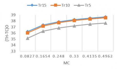
Figure 3. Variation in the difference between the outlet temperature of the hot fluid and the cold fluid and water flow rate
As shown in Figure 2, the hot water temperature increases with the increase in the water flow rate, while it decreases with the decrease in the twisted ratio. The means an increase in the heat exchange rate with cold air, whose outlet temperature increases with a decreasing twisted ratio, as shown in Figure 3. By reason of the flow disfigurement in passing through a twisted pathway, the fluid flow involvements a substantial velocity gradient, and the twisted inner tube with lesser twisted ratio leads to produced the secondary flow on lengthways of the path. The liquid flows toward the wall side of the air, and the recirculation in the flow cross-sections causes the fluid mixing to progress and increase the turbulence adversity. The improvement in blending and turbulence intensity causes the heat transfer to ameliorate. Happenning because existence the swirling flow was not present in the plain tube. Due to the occurrence of swirling flow in the annular inner tube, vortices are generated, which increases fluid mixing. Thus, the heat transfer increases with a load between the hot liquid and the cold liquid.
Figure 4. Variation in the difference between the outlet temperature of the cold fluid and the cold fluid and water flow rate
Figure 5. Contrast between the heat exchanger effectiveness and water flow rate
In addition, the difference between the external temperatures of hot water and cold air increases with the increase in water flow as shown in Figure 4. Increasing the cold air temperature with a decrease in the flow rate due to the fluid flowing at a slower speed, which helps the fluid to remain for a longer period and thus increase heat transfer. The cold air temperature increases more when the torsion rate decreases, which in turn leads to an increase in heat exchange, as explained previously. Therefore, the difference in outlet temperatures decreases with the twisted ratio when it is equal to 5. Therefore, that means the effectiveness of the heat exchanger increases with the increase in the water flow rate, as in Figure 5. The effectiveness of the heat exchanger improves by 16% when the twisted ratio is 5. This is due to the increase in heat exchange between hot water and cold air due to the twisted of the inner tube attended by an increase in the fluid momentum and flow turbulence. Since the effectiveness of the heat exchanger is the result dividing of the normal heat over the maximum heat, as the normal heat depends mainly on the cold air temperature. Therefore, an increase in the cold air temperature leads to an increase in the normal temperature and thus increases the effectiveness of the heat exchanger. From the hydraulic side, the effect of increasing the number of turns of the twisted tube on the pressure drop that accompanies the increase in heat transfer must be taken into account.
Figure 6. Contrast between the pressure drop and water flow rate
Figure 7. Variation between the overall performances and water flow rate
In Figure 6 denoted phenomenon presents a senior vanishing the momentum and producing the pressure drop. Also, as a result of the flow blockage increasing and the flow channel lengthening the pressure drop increases. The flow experienced higher deformation along the path. The intensity of the secondary flow increase, leads to increase the heat transfer and pressure drop when Tr=5 where vortices are formed due to the high twisted. As a result of the increased pressure drop penalty caused by helical flow, considerable flow mixing occurs. This is explained by the increased swirl intensity imparted to the flow near the tube wall, which results in more efficient boundary layer interruption along the flow path. Similarly, increased heat transfer performance results in a greater pressure drop penalty. While the overall performance decreases with the increase in the water flow rate, as in Figure 7. This is due to the high hydrodynamic performances (total pressure drop). Overall performance improves when the flow rate is 0.0827 and twisted ratio is 5 by 13%. On the other hand, overall performance improves by 15% when the twisted ratio is 5.
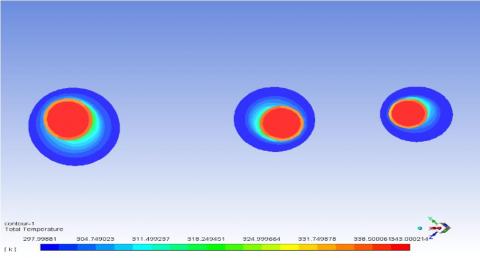
Figure 8 shown temperature field of the cross-section of a double circular twisted tube with a twisted ratio equal to 5. The inner twisted circular tube reasons the fluid to flow rotationally and procedure the secondary flow, enhancing the fluid mixing in the annulus. The temperature in the annulus of the model with a twisted inner tube is more significant. The annular flow due to the twist moves the hot flow into the tube wall at a lower temperature, which enhances heat transfer. Furthermore, the temperature contours are rotationally proportional to the tube center in the twisted inner tube. noticed that the thermal boundary layer in the inner tube wall is clearly broken due to the increase in velocity and the secondary flow when the value of twisted ratio is 5. Also, the behavior of a twisted tube approximates that of a straight tube when the twisted ratio increases so the fluid mixing decreases because of the decrease in secondary flow. The low temperature region increases with an increasing twisted ratio. Therefore, decreasing the twisted ratio, which means increasing the twisted in the inner tube, greatly improves the mixing of liquids in the annulus. To study the flow physics and the effect of the twisted tube extensively the streamlines are shown in Figure 9 for the wall twist pitch. According to Figure 9, the flow is affected by the wall twists. Due to the generated velocity gradient, two independent vortices are generated at typical cross-sections along with the flow after the first turn. These vortices rotate with twisting of the inner tube wall without fusion. According to Figure 9, the maximum velocity was located nearer to the surface of the inner twisted circular tube. whereas, the maximum and minimum velocities in the average flow direction are ± 22.8 m/ s.
Figure 8. Temperature contours for double circular twisted tubes with twisted ratio 5
Figure 9. Streamlines in the double circular twisted tube with elliptical cross-section and twist ratio of 5
In this work, a numerical study was conducted to show the effect of the twisted circular tube in a double-tube heat exchanger for several twisted ratios (5, 10, 15) on pressure drop, the heat exchanger effectiveness, and the overall performance. The main results are summarized as follows:
1-There is a capability of using a twisted circular tube heat exchanger type due to its high thermal performance compared with a plain tube.
2- Improving fluid mixing in the tube annulus due to the twisting of the inner tube.
3- The computational results exhibit that a twist ratio of 5 has the best overall thermal-hydraulic performance.
4- The heat exchanger effectiveness increases as 14.8% when the flow rate is 0.4962 and Tr =5.
5- Overall performance improves by 13%. when the flow rate is 0.082, and Tr = 5.
The author would like to thank to my dear supervisor Prof. dr. Khudheyer S. Mushatet, Professor of heat transfer in the department of mechanical Engineering College of Engineering, University of Thi-Qar.
|
LMTD |
Logarithmic mean temperature difference |
|
$\in$ |
Effectiveness |
|
Cp |
Specific heat (J/kg.K) |
|
$\eta$ |
Overall Performance |
|
m |
mass (kg) |
|
$\Delta P$ |
Pressure drop (pa) |
|
Re |
Reynolds number |
|
$\rho$ |
Density (kg/m3) |
|
Dh |
Hydraulic diameter (m) |
|
Tr |
Twisted ratio |
|
P |
Twisted pitch (mm) |
|
Greek symbols |
|
|
$\mu$ |
dynamic viscosity, kg. m-1.s-1 |
[1] Bergles, A.E. (2011). Recent developments in enhanced heat transfer. Heat and Mass Transfer, 47(8): 1001-1008. https://doi.org/10.1007/s00231-011-0872-y
[2] Mushatet, K.S., Hmood, H.M. (2021). Numerical investigation for heat transfer enhancement in a triangular twisted tube. ARPN Journal of Engineering and Applied Sciences, 16(5): 593-599.
[3] Dzyubenko, B.V., Yakimenko, R.I. (2001). Efficiency of heat transfer surfaces using the method of effective parameters. Heat Transfer Research, 32(7-8): 8. https://doi.org/10.1615/HeatTransRes.v32.i7-8.150
[4] Asmantas, L.A., Nemira, M.A., Trilikauskas, V.V. (1985). Coefficients of heat transfer and hydraulic drag of a twisted oval tube. Heat Transfer. Soviet Research, 17(4): 103-109.
[5] Tang, X., Dai, X., Zhu, D. (2015). Experimental and numerical investigation of convective heat transfer and fluid flow in twisted spiral tube. International Journal of Heat and Mass Transfer, 90: 523-541. https://doi.org/10.1016/j.ijheatmasstransfer.2015.06.068
[6] Bhadouriya, R., Agrawal, A., Prabhu, S.V. (2015). Experimental and numerical study of fluid flow and heat transfer in a twisted square duct. International Journal of Heat and Mass Transfer, 82: 143-158. https://doi.org/10.1016/j.ijheatmasstransfer.2014.11.054
[7] Bhadouriya, R., Agrawal, A., Prabhu, S.V. (2015). Experimental and numerical study of fluid flow and heat transfer in an annulus of inner twisted square duct and outer circular pipe. International Journal of Thermal Sciences, 94: 96-109. https://doi.org/10.1016/j.ijthermalsci.2015.02.019
[8] Khoshvaght-Aliabadi, M., Arani-Lahtari, Z. (2016). Proposing new configurations for twisted square channel (TSC): Nanofluid as working fluid. Applied Thermal Engineering, 108: 709-719. https://doi.org/10.1016/j.applthermaleng.2016.07.173
[9] Promthaisong, P., Chuwattanakul, V., Eiamsa-ard, S. (2020). 3D numerical analysis of thermal-hydraulic behaviors of turbulent flow inside twisted square ducts. Thermophysics and Aeromechanics, 27(3): 345-357. https://doi.org/10.1134/S086986432003004X
[10] Dong, X., Jin, X., Li, P., Bi, Q., Gui, M., Wang, T. (2020). Experimental research on heat transfer and flow resistance properties in spiral twisted tube heat exchanger. Applied Thermal Engineering, 176: 115397.
[11] Eiamsa-Ard, S., Promthaisong, P., Thianpong, C., Pimsarn, M., Chuwattanakul, V. (2016). Influence of three-start spirally twisted tube combined with triple-channel twisted tape insert on heat transfer enhancement. Chemical Engineering and Processing: Process Intensification, 102: 117-129.
[12] Omidi, M., Farhadi, M., Jafari, M. (2018). Numerical study on the effect of using spiral tube with lobed cross section in double-pipe heat exchangers. Journal of Thermal Analysis and Calorimetry, 134(3): 2397-2408. https://doi.org/10.1007/s10973-018-7579-y
[13] Khan, M.S., Zou, R., Yu, A. (2021). Computational simulation of air-side heat transfer and pressure drop performance in staggered mannered twisted oval tube bundle operating in crossflow. International Journal of Thermal Sciences, 161: 106748. https://doi.org/10.1016/j.ijthermalsci.2020.106748
[14] Liu, S., Yin, Y., Tu, A., Zhu, D. (2020). Experimental investigation on shell-side performance of a novel shell and tube oil cooler with twisted oval tubes. International Journal of Thermal Sciences, 152(4): 106290. https://doi.org/10.1016/j.ijthermalsci.2020.106290
[15] Yu, C., Zhang, H., Wang, Y., Zeng, M., Gao, B. (2020). Numerical study on turbulent heat transfer performance of twisted oval tube with different cross sectioned wire coil. Case Studies in Thermal Engineering, 22: 100759. https://doi.org/10.1016/j.csite.2020.100759
[16] Tan, X.H., Zhu, D.S., Zhou, G.Y., Zeng, L.D. (2013). Heat transfer and pressure drop performance of twisted oval tube heat exchanger. Applied thermal engineering, 50(1): 374-383. https://doi.org/10.1016/j.applthermaleng.2012.06.037
[17] Meyer, J.P., Abolarin, S.M. (2018). Heat transfer and pressure drop in the transitional flow regime for a smooth circular tube with twisted tape inserts and a square-edged inlet. International Journal of Heat and Mass Transfer, 117: 11-29. https://doi.org/10.1016/j.ijheatmasstransfer.2017.09.103
[18] Sivakumar, K., Rajan, K. (2015). Experimental analysis of heat transfer enhancement in a circular tube with different twist ratio of twisted tape inserts. International Journal of Heat and Technology, 33(3): 158-162.
[19] Ponnada, S., Subrahmanyam, T., Naidu, S.V. (2019). A comparative study on the thermal performance of water in a circular tube with twisted tapes, perforated twisted tapes and perforated twisted tapes with alternate axis. International Journal of Thermal Sciences, 136: 530-538. https://doi.org/10.1016/j.ijthermalsci.2018.11.008
[20] Mushatet, K.S., Rishak, Q.A., Fagr, M.H. (2020). Experimental and numerical investigation of swirling turbulent flow and heat transfer due to insertion of twisted tapes of new models in a heated tube. Applied Thermal Engineering, 171: 115070. https://doi.org/10.1016/j.applthermaleng.2020.115070
[21] Mushatet, K.S., Youssif, F.K. (2018). Modeling whirling motion and heat transfer intensification in a heated tube with a twin twisted tape. In 2018 International Conference on Advance of Sustainable Engineering and its Application (ICASEA), pp. 215-220. https://doi.org/10.1109/ICASEA.2018.8370984
[22] Mushatet, K.S., Youssif, F.K. (2018). Prediction the thermal and hydrodynamic performance of nano fluids flow in a tube coupled with double twisted tape. Arpn Journal of Engineering and Applied Sciences, 13: 12.
[23] Farnam, M., Khoshvaght-Aliabadi, M., Asadollahzadeh, M.J. (2018). Heat transfer intensification of agitated U-tube heat exchanger using twisted-tube and twisted-tape as passive techniques. Chemical Engineering and Processing-Process Intensification, 133: 137-147. https://doi.org/10.1016/j.cep.2018.10.002
[24] Samruaisin, P., Kunlabud, S., Kunnarak, K., Chuwattanakul, V., Eiamsa-ard, S. (2019). Intensification of convective heat transfer and heat exchanger performance by the combined influence of a twisted tube and twisted tape. Case Studies in Thermal Engineering, 14: 100489. https://doi.org/10.1016/j.csite.2019.100489
[25] Gnanavel, C., Saravanan, R., Chandrasekaran, M. (2020). Heat transfer enhancement through nano-fluids and twisted tape insert with rectangular cut on its rib in a double pipe heat exchanger. Materials Today: Proceedings, 21: 865-869. https://doi.org/10.1016/j.matpr.2019.07.606
[26] Feizabadi, A., Khoshvaght-Aliabadi, M., Rahimi, A.B. (2019). Experimental evaluation of thermal performance and entropy generation inside a twisted U-tube equipped with twisted-tape inserts. International Journal of Thermal Sciences, 145(93): 106051. https://doi.org/10.1016/j.ijthermalsci.2019.106051
[27] Fagr, M.H., Rishak, Q.A., Mushatet, K.S. (2020). Performance evaluation of the characteristics of flow and heat transfer in a tube equipped with twisted tapes of new configurations. International Journal of Thermal Sciences, 153: 106323. https://doi.org/10.1016/j.ijthermalsci.2020.106323
[28] Abbasian Arani, A.A., Sadripour, S., Kermani, S. (2017). Nanoparticle shape effects on thermal hydraulic performance of boehmite alumina nanofluids in a sinusoidal–wavy mini-channel with phase shift and variable wavelength. Int J Mech Sci., 128: 550-563. https://doi.org/10.1016/j.ijmecsci.2017.05.030
[29] Soe, T.M., Khaing, S. (2017). Comparison of turbulence models for computational fluid dynamics simulation of wind flow on cluster of buildings in mandalay. International Journal of Scientific and Research Publications, 7(8): 337-350.
[30] Cable, M. (2009). An evaluation of turbulence models for the numerical study of forced and natural convective flow in Atria. Doctoral dissertation, Queen's University.