Fatima Zohra Bakhti* | Mohamed Si-Ameur
© 2021 IIETA. This article is published by IIETA and is licensed under the CC BY 4.0 license (http://creativecommons.org/licenses/by/4.0/).
OPEN ACCESS
The aim of this study is to examine by means of three-dimensional numerical simulations the thermal-fluid features in elliptical pin fin heat sink. The passive heat transfer enhancement technique is used to comprehend and control the cooling process. This passive methodology is based on pin fins arrangement, hydrodynamic and geometrical parameters. The present numerical results are confronted with experimental measurements in open literature which used one-dimensional model to explore the thermal field. A good agreement was found especially around the optimal fins dimensions. A parametric study has been carried out to deeply analyse the three-dimensional thermal-fluid fields of the heat sink for various key parameters range such the Reynolds number (Re = 50–250) and the aspect ratio (γ=H/d=5.1-9.18). Some new observations and results are obtained thanks to numerical simulations as tool of investigation. It is shown that the fins circumferential temperature is almost uniform. Furthermore, a better cooling is obtained when the Reynolds number increases mainly when the inlet velocity u0> 0.3m/s. The most suitable value of the aspect ratio is attained for γ=8.16, which ensure an optimal cooling process of the pins. A new global Nusselt number correlation was developed for engineering applications.
mixed convection, heat sink, elliptical pin fins, cooling device, CFD
Due to the rapid growth of electronic technology, the volume of devices is considerably reduced while the performance increases favorably and in a superior way. This trend inexorably induces an augmented heat rate per device’s volume. In this situation, the great challenge for manufacturers is to ensure an efficiently cooling process. Indeed, any heat excess without proper removal alters the device life and superfluous heating can even affect its ordinary function. Air heat sink remains the most output for the electronics industry, mainly due to their low price and high consistency. The purpose is to extract the suitable configuration which undergoes a higher thermal efficiency. Their role is to hold the system temperature below the manufacturer’s stated maximum value. To conceive an adequate heat sink in terms of thermal performance, it is important to carry out numerical and experimental investigations to analyse heat transfer features in several situations for different pin-fin arrays arrangement. The research in this context has attracted not only campus laboratories, but also industrial ones.
The open literature survey has highlighted the below scientific works. Sparrow and Larson [1] experimentally studied a pin fin array under a new fluid flow arrangement. The main objective was to get the coefficient of heat transfer along the array. They found that the fins located at the edge of the heat sink presented elevated coefficients of heat transfer than those within the core of the heat sink. Zografos and Sunderland [2] investigated natural convection in a pin fins heat sink with an aligned and staggered arrangement. The inline arrays have been shown to provide better thermal performance than the staggered ones. Chapman et al. [3] performed a detailed experimental analysis of the forced convection in heat sinks with different shapes of pin fin (square, circular and elliptical). The superiority of the elliptical pin thermal performance against the rectangular pin heat sink was obtained. Tahat et al. [4] experimentally examined the forced convection in a heat sink with two arrangements of fins; aligned and staggered. The optimal pitch between the fins was calculated in the longitudinal and transversal directions. Indeed, the variation of the Nusselt number with the Reynolds number and the spacing of the fins has been determined.
Kobus and Oshio [5, 6] investigated a pin-fin heat sink by means of a theoretical and experimental approach. An optimum of fin spacing has been obtained by examining the effects of several fin parameters. Furthermore, the elaborate theoretical model was shown to be in agreement with the experiments. Khan et al. [7] examined the effect of the shape of the fins on the thermal performance of the heat sink. They have used rectangular plate fins as well as circular, elliptical and square shape cross-section pin-fins with the same perimeter. Their results showed that the elliptical fin gives the highest heat transfer coefficient and low drag force. On the other hand, the rectangular fins give the best values for total entropy generation. The square fins offer the low results for the heat coefficient, drag force and total entropy generation. They also noticed that the fin profile is closely related to the aspect ratio and the Reynolds number. Sahiti et al. [8, 9] studied numerically the impact of the pin shape of on the thermal performance and pressure drop. They found that the elliptical profile has been shown to perform best in a sample of six shapes.
Yakut et al. [10] performed experiments to study the effect of dimensions of hexagonal fins and the pitch between fins on pressure drop and thermal resistance. Yang et al. [11] investigated experimentally a heat sink by considering different cross-section of pin fin; elliptic, square and circular. They have shown that the elliptic form with the staggered arrangement gives the lowest values of the pressure drop and thermal resistance. Seyf and Layeghi [12] investigated the forced convective heat transfer in six pin fin heat sink having an elliptic cross-section. Their results indicated that the insertion of metallic foam into the heat sink improves its thermal efficiency with a moderate increase in pressure drop. Deshmukh and Warkhedkar [13] have reported a detailed literature analysis of the thermal efficiency of heat sinks with different shapes of pin fin and covering the three modes of heat transfer; natural, forced and mixed convection. Chen and Jan [14] have presented a 3D numerical approach to study the forced convection in cylindrical pin-fins and plate-fins heat sink using COMSOL software. They found that the cylindrical fins give higher heat dissipation than that of plate fins. Kumar and Bartaria [15] studied numerically the thermal and hydrodynamic characteristics of elliptical pins confined between two plate fins. Their results show that the finned heat sinks with elliptical pins perform better than the plate ones.
Deshmukhand and Warkhedkar [16] experimentally investigated mixed convection around elliptical pin fins. A theoretical model was established to determine the effect of different parameters such as the heat sink void fraction, aspect ratio and longitudinal and transversal fin pitch on the thermal performance of a heat sink. Matsumoto et al. [17] carried out both a numerical and experimental investigation to study natural convection in five kinds of pin fin heat sink. They have analyzed the effect of the fins number and the geometric parameters on the thermal efficiency. Liu et al. [18] have presented a comparative study of hydrodynamic and heat transfer performances of heat sinks with a staggered arrangement of elliptical, circular and diamond fins mounted in a rectangular channel.
The cylindrical pin fins heat sink was studied numerically by Yang et al. [19]. They analyzed the effect of the Reynolds number, volume fraction and fin material on the heat sink thermal efficiency. They found an optimal diameter and number of fins which maximizes the heat transfer. Xia et al. [20] carried out an experimental and numerical investigation to study a laminar flow with heat transfer in a circular pin-fin, square pin-fin and diamond pin-fin micro heat sinks. The results obtained showed that diamond pin-fin heat sink has better heat transfer performance and the vortexes are very much easily involved in the main flow than those in the other two types of heat sinks. Yadav and Pandey [21] performed a numerical study of convective heat transfer using commercial solver COMSOL Multiphysics in a heat sink with various shapes of the fins: cylindrical, elliptical, sprocket, kite, channeled, and triangular. They found that the heat transfer from pin-fin increases with an increase in inlet velocity. Their results indicated that kite and elliptical shape have a greater effect on Nusselt number and heat transfer coefficient.
Kewalramani et al. [22] have performed an experimental investigation to study the laminar flow and heat transfer in a heat sink with elliptic cross-section fins. They proposed correlations of the Nusselt number and the Poiseuille number as a function of the Reynolds number and the Prandtl number. The characteristics of heat transfer and flow field of a water-cooled pin-fin heat sink were numerically studied by Rezaee et al. [23]. They analyzed the influence of pin-length and longitudinal-pitch of heat sink on the heat transfer and pressure drop.
The focus of the present work is to study numerically the mixed convection in a heat sink with elliptical pin-fins. The complete geometry of the heat sink is studied by means of 3D numerical simulations as tool of investigation with high resolutions, in order to be more precise and get closer to a real configuration. A great attention is paid to the qualitative (based on 3D flow visualisations to show the vortex interactions and modification of flow behaviour with fins geometrical dimensions) and quantitative analysis to highlight the thermal and dynamics fields. The goal is to comprehend the flow topology and then improve passively the cooling process with minimal pressure drop by means of the geometrical dimensions and hydrodynamic inlet condition (flow rate, Re...). Furthermore, the purpose is to elaborate a new numerical database versus the experimental work of Deshmukh and Warkhedkar [16], in order to contribute to show new results with more precise details which are inaccessible experimentally. Thus, the effects of the fins aspect ratio and velocity inlet on the thermal resistance, Nussselt number and fin efficiency are explicitly taken into account. In this context, we have followed our strategy which has been adopted in the previous works [24, 25]. The remainder of this scientific article is structured as follows: Section 2 introduces the Mathematical and physical model of the problem with emphasis on boundary conditions, Section 3 devoted to the numerical simulation procedure and Section 4 results and discussion. Finally, a conclusion is presented.
2.1 Physical models
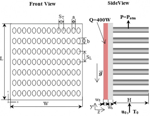
Figures 1& 2 illustrated the heat sink which is investigated in this paper. In order to confront numerical results against experimental measurements available in the open literature especially the work of Deshmukh and Warkhedkar [16], the target configuration is described as follows. The heat sink consists of 14x7 fins having an elliptic cross-section with inline arrangement and for semi-minor axis a=8mm and semi-major axis b=12mm.
Figure 1. Designed geometry of pin-fin heat sink
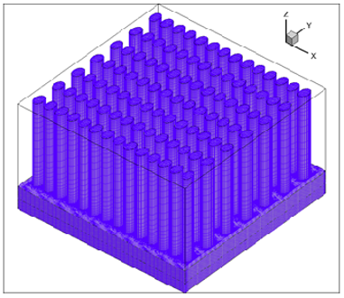
Figure 2. Isometric view of studied heat sink
The pins-fins sections are attached to a solid volume of parallelepiped form with dimensions (W x L x wb=164mm x 164mm x 12mm). SL=22.5mm and ST=11.25mm are respectively the longitudinal and transversal pitches between the fins. The heat sink is made on the basis of Aluminium alloy (K=202.4 W/m.K), it is attached to an electronic component of Sillicium (K=130 W/m.K), which produces a heat flux Q=400W. The coolant fluid flows along the y-axis according to the inlet condition.
2.2 Governing equations and boundary conditions
The below equations, let to elaborate a three-dimensional numerical model to study steady air incompressible flow with mixed convective heat transfer by means of numerical simulations. All the fluid thermophysical properties are considered constant in the range of the temperature variation. However, the density varies according to the Boussinesq approximation.
Following the considerations above, the governing equations of mass, momentum and energy conservation are written in vector form as follows:
$\nabla . \overrightarrow{\mathrm{u}}=0$ (1)
$\overrightarrow{\mathrm{u}} . \nabla \overrightarrow{\mathrm{u}}=-\frac{1}{\rho_{0}} \overrightarrow{\nabla \mathrm{p}}+\nu . \Delta \overrightarrow{\mathrm{u}}+\overrightarrow{\mathrm{g}} . \beta .\left(\mathrm{T}-\mathrm{T}_{0}\right)$ (2)
$\overrightarrow{\mathrm{u}} . \vec{\nabla} \mathrm{T}=\frac{\mathrm{K}_{\mathrm{f}}}{\rho_{0} . \mathrm{C}_{\mathrm{p}}} \Delta \mathrm{T}$ (3)
$\mathrm{K}_{\mathrm{S}} . \Delta \mathrm{T}+\dot{\mathrm{q}}_{\mathrm{s}}=0$ (4)
where, $\overrightarrow{\mathrm{u}}$ is the vector field of flow velocity, the velocity of x, y and z-coordinate are represented as u, v and w, correspondingly; the density of heat transfer fluid is defined as ρ; ν is the kinematic viscosity; p is the pressure value of heat transfer fluid; Cp is defined as the specific heat capacity in the constant pressure; β is the thermal expansion coefficient; Kf and Ks are the heat conductivity of heat transfer fluid and solid.
The heat flow generated per unit volume;
$\dot{q}_{s}=\frac{Q}{V}\left[W / m^{3}\right]$
The boundary conditions are chosen with a fidelity to realistic situations. In this context, the adopted ones are as follows:
$\frac{\partial \mathrm{u}}{\partial \mathrm{x}}=\frac{\partial \mathrm{v}}{\partial \mathrm{x}}=\frac{\partial \mathrm{w}}{\partial \mathrm{x}}=\frac{\partial \mathrm{T}}{\partial \mathrm{x}}=0$, P=Patm
- For both left (x=0) and right(x=W) sides of the computational domain, a symmetry condition is prescribed to ensure:
$\frac{\partial u}{\partial x}=\frac{\partial w}{\partial x}=\frac{\partial T}{\partial x}=0, v=0$
-A heat source $\dot{q}_{s}$ produced by the electronic component:
$\dot{\mathrm{q}}_{\mathrm{s}}=\frac{\mathrm{Q}}{\mathrm{V}}=1487210 \mathrm{~W} / \mathrm{m}^{3}$
with Q=400W, V=164mmx164mmx10mm=268960 mm3.
- A continuity condition at the interface is prescribed between the conduction in the solid and the convection in the fluid so:
Ts=Tf
$\left.\mathrm{K}_{\mathrm{S}} \frac{\partial \mathrm{T}}{\partial \mathrm{n}}\right|_{\text {wall }}=\left.\mathrm{K}_{\mathrm{f}} \frac{\partial \mathrm{T}}{\partial \mathrm{n}}\right|_{\text {wall }}$ (5)
2.3 Data analysis
The total heat transfer rate, inlet and outlet mean temperature and mass flow rate were rigorously tracked, by considering explicitly the hydraulic diameter concept in Fluent Software. Hence, we used the below relationships to compute the Nusselt number, the thermal resistance and the fins efficiency:
-The Reynolds number is calculated by:
$\mathrm{Re}=\frac{\rho \mathrm{u}_{0} \mathrm{~d}}{\mu}$ (6)
$\mathrm{d}=\sqrt{4 \mathrm{ab}}$ is the mean diameter of elliptical pin fin [16].
-The average Nusselt number is defined by:
$\overline{\mathrm{Nu}}_{\mathrm{d}}=\frac{\overline{\mathrm{h}} . \quad \mathrm{d}}{\mathrm{K}_{\mathrm{f}}}$ (7)
where, the average heat transfer coefficient is calculated by:
$\overline{\mathrm{h}}=\frac{\mathrm{q}_{\mathrm{c}}}{\mathrm{A} .\left(\overline{\mathrm{T}}_{\mathrm{w}}-\overline{\mathrm{T}}_{\mathrm{m}}\right)}$ (8)
$\overline{\mathrm{T}}_{\mathrm{w}}=\frac{1}{\mathrm{~A}} \iint \mathrm{T} . \mathrm{d} \mathrm{A}$ (9)
$\overline{\mathrm{T}}_{\mathrm{m}}$ is the mean fluid temperature defined by:
$\overline{\mathrm{T}}_{\mathrm{m}}=\frac{\iint_{\mathrm{V}} \mathrm{TudV}}{\iiint_{\mathrm{V}} \mathrm{udV}}$ (10)
-The thermal resistance Rth is defined as [6, 16];
$\mathrm{R}_{\mathrm{th}}=\frac{\overline{\mathrm{T}}_{\mathrm{b}}-\mathrm{T}_{0}}{\mathrm{q}_{\mathrm{c}}}$ (11)
where, $\overline{\mathrm{T}}_{\mathrm{b}}$ is the mean temperature of the heat sink base;
$\overline{\mathrm{T}}_{\mathrm{b}}=\frac{1}{\mathrm{~A}} \iint \mathrm{T} . \mathrm{d} \mathrm{A}$ (12)
-The pressure drag coefficient:
$\mathrm{C}_{\mathrm{d}}=\frac{\Delta \mathrm{p}}{0.5 . \rho . \mathrm{u}_{0}^{2}}$ (13)
where, the pressure drop Δp across the heat sink is
Dp=Pinlet- Pout
-The fin efficiency is defined by:
$\eta=\frac{\tanh (\mathrm{mH})}{\mathrm{mH}}$ (14)
$\mathrm{m}=\sqrt{\frac{4 \mathrm{~h}}{\mathrm{~K}_{\mathrm{s}} \mathrm{d}}}$ (15)
2.4 Numerical procedure
In this 3D parametric study, the numerical experiments regarding the heat sink thermal performances are carried out for various aspect ratios of the pin fins and inlet hydrodynamic conditions. The design of geometries and meshes are elaborated by using the Gambit software (a pre-processor of the FLUENT commercial code).
The finite volume method was employed to discretise the governing Eqns. (1-4) and the boundary conditions by integration through finite control volumes; Quick scheme was used for the discretization of convection and diffusion terms. The acquired algebraic equations are solved by means of a numerical procedure based on SIMPLE (Semi-Implicit Method for Pressure-Linked Equations) algorithm. The solution was considered converged when the normalized residuals of continuity and momentum equations are less than 10-3 while that of the energy equation was fixed at 10-6. The computing resources are based on 8 processor DELL station.
2.5 Study of grid independence
The accuracy of the numerical simulation depends on the quality of the mesh. In this situation and in order to have a good compromise between the computation time which is highly cost in 3D and the precision of the results, the choice of an adequate mesh is crucial. In this study, a refined hexahedral mesh was used near the walls and in some critical regions where the velocity and temperature gradients are important as it is shown on Figure 3.
Furthermore and to choose the suitable mesh, several tests were carried out to check the influence of the mesh on the precision of the results. For this purpose, four meshes were considered and tested for the campaign of grid independency.
Figure 3. Isometric view of configuration mesh
Table 1 summarises the results of walls and fluid mean temperature values, convective heat flux, thermal resistance, mean convection coefficient and the mean Nusselt number. It shows that the results obtained by these mesh grids are correlated. However, the highly cost time in the case of the last grid and the good performance of the fine mesh, let to definitively opt for it within all the below numerical computations.
Table 1. Grid independence study
|
Nbr nods |
$\overline{\mathrm{T}} \mathrm{w}$ (K) |
$\overline{\mathrm{T}} \mathrm{b}$ (K) |
qc (W) |
Rth (K/W) |
$\overline{\mathrm{T}}$m (K) |
$\overline{\mathrm{h}}$ (W/K.m2) |
$\overline{\mathrm{Nu}}$ |
|
2216056 coarse |
427.764 |
434.953 |
312.812 |
0.453 |
375.780 |
22.029 |
9.103 |
|
3448899 intermediate |
425.264 |
432.318 |
292.287 |
0.476 |
374.256 |
20.977 |
8.668 |
|
5901789 fine |
427.218 |
434.315 |
299.450 |
0.471 |
375.982 |
21.396 |
8.841 |
|
7043527 very fine |
427.068 |
434.172 |
296.295 |
0.475 |
375.872 |
21.187 |
8.755 |
3.1 Validation of numerical simulation
The accuracy of the present numerical results is verified with the available experimental measurements published in the open literature. Numerical simulations are carried out with the same input data. The confrontation is provided on Figures 4-6, it can be seen that a good agreement is achieved. The small discrepancies can be due to the one dimensional approach of the correlation used by Deshmukh and Warkhedkar [16]. Therefore, the numerical model in the present study is satisfactory and the numerical results are consistent.
Figure 4. Average Nusselt number variation versus the aspect ratio
Figure 5. Average Nusselt number variation versus the Reynolds number
Figure 6. Average thermal resistance variation versus the inlet velocity
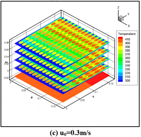
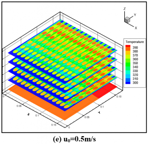
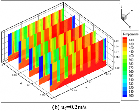
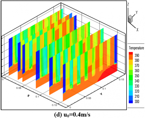
3.2 Temperatures fields of the heat sink
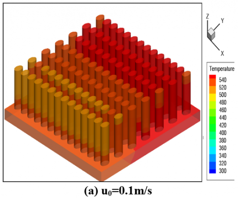
Figure 7 shows the temperature contour in the pin fin heat sink for an aspect ratio $\gamma$=8.16. One can see that for all inlet velocity values (u0=0.1m/s, 0.2m/s, 0.3m/s, 0.4m/s, 0.5m/s), the fins circumferential temperature is almost uniform. The temperature difference between two consecutive lines of pin fin decreases continually in the flow direction, from the heat sink bottom until the seventh fins row. That is due to the progressive increase of the vertical velocity, which lets to maintain the cooling process operating for all the system.
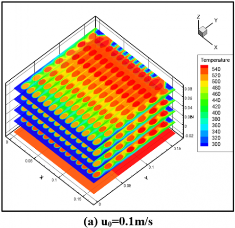
The horizontal and vertical cross sections of the air temperature contours are illustrated respectively on Figures 8 & 9. It is obvious that for each inlet velocity value u0, the lowest air temperatures are located upstream of the fins and the highest values downstream along the air flow direction. The air velocity is low in the recirculation zones downstream of the fins which induce an air temperature augmentation. The velocity decreasing in the flow direction leads to different thermal boundary layer thickness of rows; one can notice that the one in the first row is thinner than that of the seventh.
Figure 7. Contours of static temperature in the solid heat sink for γ=8.16
Figure 8. Fluid(air) contours static temperature in different horizontal planes for γ=8.16
The thermal performance of the heat sink is calculated on the basis of the temperature difference $\Delta$T variation, between the inlet heat sink and exit. Figure 10, indicates the variation of $\Delta$T with u0 and the fin aspect ratio $\gamma$. It is shown that $\Delta$T decreases with increasing of u0 and $\gamma$.
The convective transfer rate is directly influenced by the aspect ratio $\gamma$ and therefore with the height of the fins. The use of high fins (high aspect ratio) gives a higher exchange surface with an increase of the heat transfer rate. Also, the air mass flow increases as the inlet surface augments (Figure 11). Consequently, the outlet air temperature decreases gradually for high inlet velocities u0> 0.3m/s.
Figure 9. Fluid(air) contours static temperature in different vertical planes for γ=8.16
Figure 10. Temperature difference variation versus inlet velocity and aspect ratio γ
Figure 11. Air mass flow variation with inlet velocity and aspect ratio γ
3.3 Vector velocity and path lines
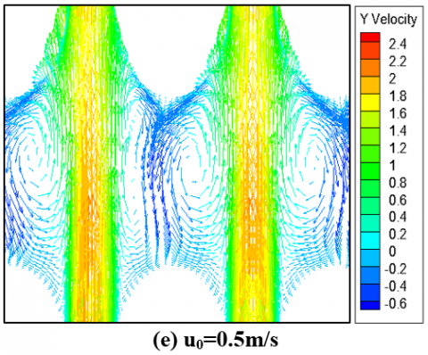
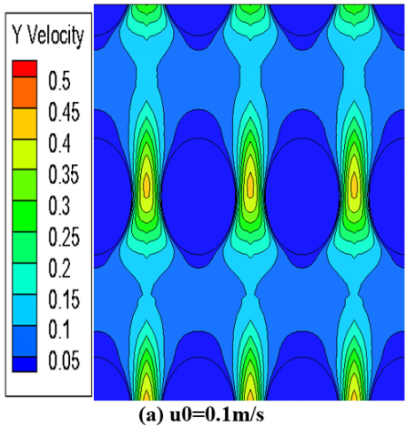
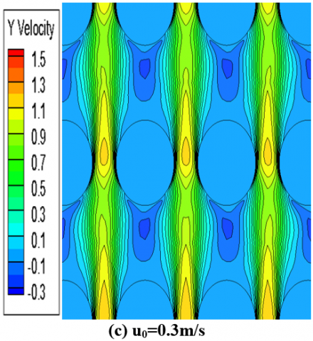
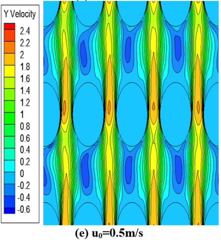
Figures 12 & 13 illustrate the velocity vector plots and velocity contours for $\gamma$=8.16 in mid-plane (z=0.04) for different inlet velocity values. It is evident that the velocity profile at the heat sink entry remains uniform. The velocity vector direction changes as the fluid particles approach to the pins and move over them. It can be also noticed a velocity increase in the space between the pin in the longitudinal direction. This is due to the reduction in the section of the fluid passage. In this area, the friction coefficient remains important. The acceleration of the hot fluid privileges the heat transfer by convection. Also, the velocity profile is deformed when the fluid is close to the heated fins. These deformations induce three dimensional thermal-fluid fields.
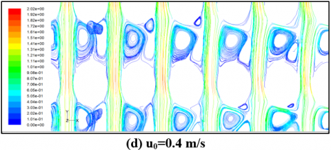
Figure 14 shows the flow path lines in mid-plane (z=0.04) for $\gamma$=8.16 and for various u0. For uo=0.1m/s, the flow behaves in a creeping manner because the forces of inertia being low. Furthermore, a fluid attachment to the fins without any separation is observed. The flow is balanced for each column of fins compared to its central axis and also between the upstream and the downstream of the fin.
For u0>0.1, the inertia forces increase and prevent the boundary layer from remaining attached to the walls of the pins and start to support a depression in the wake zone.
Thus, one observes a separation after each fin; downstream two contra-rotating lobes almost symmetrical of recirculation attached to the fin are formed. The point of fastening which is defined as the place where longitudinal velocity is null, on the central axis of the wake, moves away from the fin when the velocity inlet increases. The coordinates of this point define the length of recirculation.
Figure 12. Velocity vectors in the plane z=0.04 for γ=8.16
Figure 13. Velocity vectors in the plane z=0.04 for γ=8.16
Figure 14. Flow path lines around a solid fin in the plane z=0.04 for γ=8.16
Figure 15. Thermal resistance variation versus the inlet velocity
For more assessment of the thermal fin performance, Figure 15 shows the thermal resistance for various pin heights and for various inlet velocities. One can observe that the thermal resistance decreases with increasing of u0 and γ.
3.4 Nusselt number
The Nusselt number was calculated for all the numerical simulations. Figure 16 shows the variation of the Nusselt number with the inlet velocity, in the case of all pin-fin arrangements. It is clear that the mean Nusselt number increases with the air flow rate augmentation, which supports moreover the conduction-convective phenomenon between the fins and the fluid flow inside the heat sink.
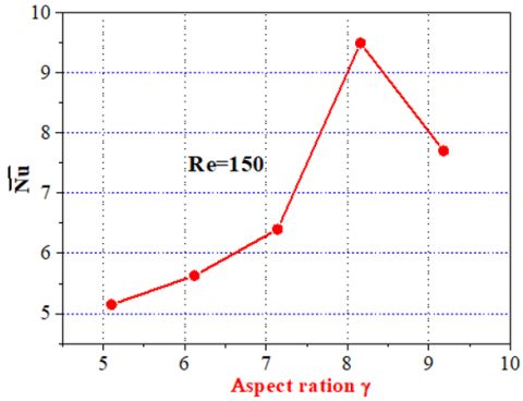
Figure 17 makes clear that as the fin height augments, the Nusselt number augments for all values of γ= 5.1–8.16 and the bad effects are detected for γ over 8.16. This can be endorsed to the temperature gradients near to the tip of the pin fins. Indeed, above γ=8.16 the thermal resistance leads to a drastic temperature decreases near the fin tips, and the thermal performance drops off. Thus, the optimum fins aspect ratio is close to 8.16.
Figure 16. Mean Nusselt number variation versus the inlet velocity
Figure 17. Mean Nusselt number variation versus the aspect ratio
This optimum is exactly the same for both the two approaches; the present numerical simulation and the experimental investigation [16], although their experimental model involves numerous simplifications. However, our approach is more precise as all the governed equations are solved in three dimensional numerical computations. Obviously the heat flux inside the fins is not unique and dispersed for all the system. The new observations presented above are due to 3D numerical simulations as tool of investigation. The Nusselt number could be correlated as a polynomial function such as equation:
$\overline{\mathrm{Nu}}_{\mathrm{d}}=\mathrm{a}_{1}+\mathrm{b}_{1} . \mathrm{Re}_{\mathrm{d}}-\mathrm{c}_{1} . \mathrm{Re}_{\mathrm{d}}^{2}$ (16)
Coefficients Data:
a1=0.36987, b1=0.07494, c1=1.21936.10-4
Where 50≤Red≤250
This new correlation can be used to engineering applications to compute the average heat energy. Table 2 summarises the new Nusselt number correlation and others issued from literature in the case of laminar flow.
3.5 Pressure drag coefficient and fin thermal efficiency
Figure 18 elucidated the variation of the pressure drag coefficient Cd with different inlet velocities and for different fin aspect ratios. It is evidently clear that Cd augments first with inlet velocity and then diminishes after it attains the pick value for u0 = 0.3m/s. For all aspect ratios, the pressure drops are roughly at the same trend. It can also be noted that Cd increases with gand consequently with the height of the fins. This is due to the increase in friction forces generated along the fins.
Figure 18. Pressure drag coefficient variation versus the inlet velocity
Figure 19. The fin efficiency variation versus the inlet velocity
Table 2. Nusselt number correlations
|
|
Nusselt Number |
Coefficients |
Conditions |
|
Present investigation |
$\overline{N u}_{d}=\mathrm{a}_{1}+b_{1} . R e_{d}-c_{1} . R e_{d}^{2}$ |
a1=0.36987 b1=0.07494 c1=1.21936x10⁻⁴ |
50≤Red≤250 Re: based on hydraulic diameter |
|
Deshmukh and Warkhedkar [16]
|
-Inline arrangement $\mathrm{Nu}_{\mathrm{d}}=1.008(\alpha)^{1.34}(\gamma)^{0.5}\left(\frac{\mathrm{Re}_{\mathrm{d}}}{\mathrm{Gr}_{\mathrm{d}}^{0.5}}\right)$ -Staggered arrangement $\mathrm{Nu}_{\mathrm{d}}=1.26(\alpha)^{1.25}(\gamma)^{0.46}\left(\frac{\mathrm{Re}_{\mathrm{d}}}{\mathrm{Gr}_{\mathrm{d}}^{0.5}}\right)$ |
0.534 ≤ α ≤ 0.884, 5.1 ≤ γ ≤ 9.18 |
$1 \leq \frac{G r_{d}}{R e_{d}} \leq 100$ |
|
Khan et al. [26] |
-For uniform wall temperature $\frac{\mathrm{Nu}_{\mathrm{L}}}{\operatorname{Re}_{\mathrm{L}}^{1 / 2} \operatorname{Pr}^{1 / 3}}=0.75-0.16 \exp \left(\frac{-0.018}{\varepsilon^{3.1}}\right)$ -For uniform wall flux $\frac{\mathrm{Nu}_{\mathrm{L}}}{\mathrm{Re}_{\mathrm{L}}^{1 / 2} \operatorname{Pr}^{1 / 3}}=0.91-0.31 \exp \left(\frac{-0.09}{\varepsilon^{1.79}}\right)$ |
a: semimajor axis of elliptical cylinder b: semiminor axis of elliptical cylinder ε: axis ratio=b/a L: characteristic length=2a |
102≤ReL≤105 |
In order to present the heat sink thermal performance, the thermal efficiency is presented in Figure 19. It can be clearly seen that the fin efficiency h decreases with increasing the inlet velocity u0 and aspect ratio γ.
In this work, a cooling process regarding to heated electronic component is studied by means of 3D numerical computations. A parametric analysis for various hydrodynamic values (inlet velocity or Reynolds numbers) and geometrical pin fin dimensions was undertaken. The finite volume method and the SIMPLE algorithm were used to solve the thermal-fluid equations. The results are confronted with the experimental measurements of pin fin heat sink; a quasi-good agreement was found. Numerical simulations were carried out for a broad variation of independent parameters; the Reynolds number Re=50-250 and the fin aspect ratio γ=5.1-9.18.
On the basis of this 3D study, the dynamical and the thermal fields are analysed qualitatively and quantitatively through numerical visualisations and the profiles of significant physical quantities. It is shown that the fins circumferential temperature is almost uniform. Furthermore, a better cooling is detected when the inlet velocity increases. An optimal value of the fin aspect ratio γ=8.16 was obtained, which let to better heat dissipation with satisfactory pressure drop. A new correlation given the evolution of the Nusselt number with the Reynolds number in such thermal system is elaborated. The present numerical experiments have highlighted more details, especially the thermal-fluid fields topology compared to the laboratory experiments. Thus, the comprehension of the cooling mechanisms involved in such system can lead to a better control of the heat dissipation to ensure a longer life device.
|
A |
heat transfer area, m2 |
|
a |
semi-minor axis of elliptical pin fin, m |
|
b |
semi-major axis of elliptical pin fin, m |
|
Cd |
pressure drag coefficient |
|
Cp |
specific heat at constant pressure, J.kg-1.K-1 |
|
d |
mean diameter, m |
|
$\overrightarrow{\mathrm{g}}$ |
gravity acceleration, m/s-2 |
|
Gr |
Grashof number |
|
$\overline{\mathrm{h}}$ |
average heat transfer coefficient, J.m-2.K-1 |
|
H |
height of pin fin, m |
|
Kf |
fluid thermal conductivity, J.m-1.K-1 |
|
KS |
solid thermal conductivity, J.m-1.K-1 |
|
L |
length of base plate, m |
|
$\overline{\mathrm{Nu}}_{\mathrm{d}}$ |
average Nusselt number based on d (=h.d/Kf) |
|
p |
Pressure, Pa |
|
pinlet |
pressure inlet, Pa |
|
pout |
pressure outlet, Pa |
|
Q |
heat produced by the electronic component, W |
|
qc |
convection heat flux, J |
|
$\dot{q}_{s}$ |
heat flux generated per unit volume, W/m3 |
|
Red |
Reynolds number based on d |
|
Rth |
thermal resistance, K/W |
|
ST |
transversal pitch, m |
|
SL |
longitudinal pitch, m |
|
Tb |
temperature of heat sink base, K |
|
Tm |
mean temperature of the fluid, K |
|
To |
inlet air temperature, K |
|
TW |
temperature of the heat sink wall, K |
|
u,v,w |
velocity components, m/s |
|
u0 |
inlet air velocity, m/s |
|
V |
volume of the electronics component, m3 |
|
W |
width of base plate, m |
|
wb |
thickness of base plate, m |
|
wS |
thickness of source volume, m |
|
x, y, z |
cartesian coordinates, m |
|
Greek symbols |
|
|
$\beta$ |
thermal expansion coefficient, K-1 |
|
ρ |
the fluid density, kg/m3 |
|
ρ0 |
the fluid density at T0, kg/m3 |
|
$\gamma$ |
aspect ratio |
|
$\eta$ |
fin efficiency |
|
ν |
kinematic viscosity (=µ/ρ), m2.s-1 |
|
µ |
dynamic viscosity, kg. m-1.s-1 |
[1] Sparrow, E.M., Larson, E.D. (1982). Heat transfer from pin-fins situated in an oncoming longitudinal flow which turns to cross flow. International Journal of Heat and Mass Transfer, 25(5): 603-614. https://doi.org/10.1016/0017-9310(82)90165-X
[2] Zografos, A.I., Sunderland, J.E. (1990). Natural convection from pin fin arrays. Experimental Thermal and Fluid Science, 3(4): 440-449. https://doi.org/10.1016/0894-1777(90)90042-6
[3] Chapman, C.L., Lee, S., Schmidt, B.L. (1994). Thermal performance of an elliptical pin fin heat sink. Proceedings of 1994 IEEE/CHMT 10th Semiconductor Thermal Measurement and Management Symposium (SEMI-THERM), pp. 24-31. https://doi.org/10.1109/STHERM.1994.288998
[4] Tahat, M., Kodah, Z.H., Jarrah, B.A., Probert, S.D. (2000). Heat transfers from pin-fin arrays experiencing forced convection. Applied Energy, 67(4): 419-442. https://doi.org/10.1016/S0306-2619(00)00032-5
[5] Kobus, C.J., Oshio, T. (2005). Development of a theoretical model for predicting the thermal performance characteristics of a vertical pin-fin array heat sink under combined forced and natural convection with impinging flow. International Journal of Heat and Mass Transfer, 48(6): 1053-1063. https://doi.org/10.1016/j.ijheatmasstransfer.2004.09.042
[6] Kobus, C.J., Oshio, T. (2005). Predicting the thermal performance characteristics of staggered vertical pin fin array heat sinks under combined mode radiation and mixed convection with impinging flow. International Journal of Heat and Mass Transfer, 48(13): 2684-2696. https://doi.org/10.1016/j.ijheatmasstransfer.2005.01.016
[7] Khan, W.A., Culham, R., Yovanovic, M.M. (2006). The role of fin geometry in heat sink performance. Journal of Electronic Packing, 128: 324-330. https://doi.org/10.1115/1.2351896
[8] Sahiti, N., Lemouedda, A., Stojkovic, D., Durst, F., Franz, E. (2006). Performance comparison of pin fin in-duct flow arrays with various pin cross-sections. Applied Thermal Engineering, 26(11-12): 1176-1192. https://doi.org/10.1016/j.applthermaleng.2005.10.042
[9] Sahiti, N., Durst, F., Geremia, P. (2007). Selection and optimization of pin cross-sections for electronics cooling. Applied Thermal Engineering, 27(1): 111-119. https://doi.org/10.1016/j.applthermaleng.2006.05.018
[10] Yakut, K., Alemdaroglu, N., Kotcioglu, I., Celik, C. (2006). Experimental investigation of thermal resistance of a heat sink with hexagonal fins. Applied Thermal Engineering, 26(17-18): 2262-2271. https://doi.org/10.1016/j.applthermaleng.2006.03.008
[11] Yang, K.S., Chu, W.H., Chen, I.Y., Wang, C.C. (2007). A comparative study of the air side performance of heat sinks having pin fin configurations. International Journal of Heat and Mass Transfer, 50(23-24): 4661-4667. https://doi.org/10.1016/j.ijheatmasstransfer.2007.03.006
[12] Seyf, H.R., Layeghi, M. (2010). Numerical analysis of convective heat transfer from an elliptic pin fin heat sink with and without metal foam insert. Journal of Heat Transfer, 132(7): 071401-1-071401-9. https://doi.org/10.1115/1.4000951
[13] Deshmukh, P.A., Warkhedkar, R.M. (2011). Thermal performance of pin fin heat sinks –a review of literature. International Review of Mechanical Engineering (IREME), 5(4): 726-732.
[14] Chen, C.T., Jan, S.H. (2012). Dynamic simulation, optimal design and control of pin-fin heat sink processes. Journal of the Taiwan Institute of Chemical Engineers, 43(1): 77-88. https://doi.org/10.1016/j.jtice.2011.06.005
[15] Kumar, V., Bartaria, V.N. (2013). CFD analysis of an elliptical pin fin heat sink using Ansys Fluent v12.1. International Journal of Modern Engineering Research (IJMER), 3(2): 1115-1122.
[16] Deshmukh, P.A., Warkhedkar, R.M. (2013). Thermal performance of elliptical pin fin heat sink under combined natural and forced convection. Experimental Thermal and Fluid Science, 50: 61-68. https://doi.org/10.1016/j.expthermflusci.2013.05.005
[17] Matsumoto, N., Tomimura, T., Koito, Y. (2014). Heat transfer characteristics of square micro pin fins under natural convection. Journal of Electronics Cooling and Thermal Control, 4(3): 59-69. https://doi.org/10.4236/jectc.2014.43007
[18] Liu, Z.G., Guan, N., Zhang, C.W., Jiang, G.L. (2015). The flow resistance and heat transfer characteristics of micro pin-fins with different cross-sectional shapes. Nanoscale and Microscale Thermophysical Engineering, 19(3): 221-243. https://doi.org/10.1080/15567265.2015.1073820
[19] Yang, A., Chen, L., Xie, Z., Feng, H., Sun, F. (2016). Constructal heat transfer rate maximization for cylindrical pin-fin heat sinks. Applied Thermal Engineering, 108: 427-435. https://doi.org/10.1016/j.applthermaleng.2016.07.150
[20] Xia, G., Chena, Z., Cheng, L., Ma, D., Zhai, Y., Yang, Y. (2017). Micro-PIV visualization and numerical simulation of flow and heat transfer in three micro pin-fin heat sinks. International Journal of Thermal Sciences, 119: 9-23. https://doi.org/10.1016/j.ijthermalsci.2017.05.015
[21] Yadav, S., Pandey, K.M. (2018). A comparative thermal analysis of pin fins for improved heat transfer in forced convection. Materials Today: Proceedings, 5(1): 1711-1717. https://doi.org/10.1016/j.matpr.2017.11.268
[22] Kewalramani, G.V., Hedau, G., Saha, S.K., Agrawal, A. (2019). Study of laminar single phase frictional factor and Nusselt number in In-line micro pin-fin heat sink for electronic cooling applications. International Journal of Heat and Mass Transfer, 138: 796-808. https://doi.org/10.1016/j.ijheatmasstransfer.2019.04.118
[23] Rezaee, M., Khoshvaght-Aliabadi, M., Abbasian Arani, A.A., Mazloumi, S.H. (2019). Heat transfer intensification in pin-fin heat sink by changing pin-length/longitudinal-pitch. Chemical Engineering & Processing: Process Intensification, 141: 107544. https://doi.org/10.1016/j.cep.2019.107544
[24] Bakhti, F.Z., Si-Ameur M. (2016). Numerical study of cooling enhancement: heat sink with hollow perforated elliptic pin fins. Comput. Therm. Sci., 8(5): 409-428.
[25] Bakhti, F.Z., Si-Ameur, M. (2019). A comparison of mixed convective heat transfer performance of nanofluids cooled heat sink with circular perforated pin fin. Applied Thermal Engineering, 159: 113819. https://doi.org/10.1016/j.applthermaleng.2019.113819
[26] Khan, W.A., Culham, J.R., Yovanovich, M.M. (2005). Fluid flow around and heat transfer from elliptical cylinders: Analytical approach. Journal of Thermophysics and Heat Transfer, 19(2): 178-185.