Palash Soni | Sruthi Lolalis | Bidyut Mazumdar | Shubhankar Bhowmick | Vivek Kumar Gaba*
© 2021 IIETA. This article is published by IIETA and is licensed under the CC BY 4.0 license (http://creativecommons.org/licenses/by/4.0/).
OPEN ACCESS
Adsorption refrigeration, being a unique and eco-friendly technology, has gained popularity over conventional refrigeration systems. The present study is aimed at developing an annular finned tube adsorber model which serves as a thermal compressor in adsorption refrigeration systems. The mathematical model is addressed numerically using finite difference discretization method and explicit scheme was used for the solution. The generalized model has been simulated for activated carbon–methanol working pair. The system has an optimum cycle time of 1800s. It was found to have a highest refrigeration capacity of 260.66 kJ/kg at a regeneration temperature of 393 K and evaporator temperature of 283 K. The highest COP (Coefficient of Performance) achieved by the system is 0.3706 at a regeneration temperature of 353 K and evaporator temperature of 283 K. A highest SCP (Specific Cooling Power) of 144.8 W/kg was obtained at an evaporator temperature of 283 K and regeneration temperature of 393 K.
activated carbon, adsorption refrigeration, finite difference method, methanol, adsorber bed
The major concerns of 21st century are energy crisis, pollution control and promoting sustainable development. These considerations have influenced almost all fields of science and technology. The strict laws and regulations, in effect, also enforce the development and improvement of techniques to deal with it. The dependency on conventional energy sources must be replaced with renewable ones to initiate and maintain sustainable development.
Refrigeration has become a vital part of our day to day life which ranges from simple air-conditioners to sophisticated cold storage systems. The present techniques based on vapor compression cycle can no longer survive because of the emerging concerns on global warming, ozone layer depletion, energy crisis, pollution, etc. The energy intensive processes can be updated with innovative techniques like adsorption systems which have less harmful impact on environment. Sorption systems are the best replacement of conventional refrigeration systems due to its various benefits. In sorption technique, both physical adsorption systems and chemical adsorption systems are available. The mass transfer and heat transfer properties affect the physical system performance while the chemical adsorption system performance is controlled by the reaction kinetics as well as the heat and mass transfer processes. Chemical adsorption has higher capacity than physical systems but physical systems can be more easily designed and maintained. The main physical adsorbents are activated carbon and activated carbon fiber, silica gel, zeolite and some porous materials like alumino-phosphates, silico-alumino-phosphates and metal organic frameworks. The major chemical adsorbents are metal chlorides, metal hydrides, metal oxides and salt hydrates. In some cases, composite adsorbents are also used [1]. Among the different working pairs in use, activated carbon–methanol working pair has its own merits over other systems like low regeneration temperature, large adsorption quantity and less adsorption heat. The adsorption heat ranges from 1800–2000 kJ/kg. The specific volume of activated carbon is usually around 0.15–0.50 cm3/g. recently, activated carbon fibers are also used as adsorbents. Experimental results show that it can increase COP by 10-20% [2]. Soni and Gaba [3] Made a study of two working pairs namely silica-gel/water and zeolite/water and reported that zeolite/water pair gave best output for the prototype. CO2 adsorption on single-walled carbon nanotubes was reported by Hu and Ruckenstein [4] where-in amongst different equations to represent the isotherms, Dubinin-Astakhov equation was found best to explain CO2 adsorption.
One of the advantages of adsorption systems is that they can be powered by renewable energy like solar energy. Curran [5] studied solar powered cooling systems and defined coefficient of performance as a common factor for comparison. Sur et al. [6] presented a thermodynamic model to evaluate the performance of a single bed single stage adsorption refrigeration system working on Silica-gel/methanol pair. The solar heat collected through a flat plate collector is used as a heat source for this system. A new design of adsorber bed (Shall and tube type) is also proposed in this study. This system produced a cooling effect of 577 kJ with a COP of 0.38 corresponding to a maximum bed temperature of 90℃. Suzuki and Sakoda [7] conducted a basic study of solar cooling systems and reported a model to fit the experimental data which provided a first step model for estimating mass and heat transfer in adsorbent beds. The dependency of adsorption on regeneration temperature using equilibrium relations was reported.
The maintenance of uniform temperature all over the adsorber is a major factor that should be taken care in adsorption systems since even small drop or increment in temperature can affect the adsorption/desorption process. As a remedy to this, recent researches are focusing on developing better designs of adsorber that can maintain uniform temperature in the adsorber bed. Fixed bed adsorber is the most common ones in use from early times itself. But later, Wang et al. [8] came out with a different design of fluidized bed in place of fixed bed with activated carbon-R134a used as the working pair. Zhao et al. [9] made both theoretical and experimental study of a tubular type adsorption system with activated carbon-methanol as the working pair and simulated the model for transient pressure process and traditional constant pressure process. Ji et al. [10] made studies on finned tube adsorber to enhance the heat transfer characteristics. The system used activated carbon-methanol working pair which showed a COP of 0.122 and gave a daily ice production of 6.5 kg.
Li et al. [11] reported a mathematical model of finned tube adsorption heat pump based on silica gel and optimized it for specified operating conditions. It was found that an optimized heat pump with improved design can produce a refrigeration effect two times greater than the non-optimized heat pump. Hong et al. [12] also made their study on a finned tube adsorption chiller and reported the effect of parameters, like fin thickness, fin height, fin pitch, diffusion coefficient, cycle time, particle size, cycle ratio, temperature of hot water, fluid velocity and porosity, on the performance of the system. Of these, fin thickness and temperature of hot water were found to be the most significant parameters. Liu and Leong [13] reported a numerical study of a novel cascading adsorption cooling cycle consisting of two zeolite beds and a silica gel bed and proved the existence of optimal temperature for better performance. Numerical modelling of combined heat and mass transfer in the adsorbent bed of a zeolite/water cooling system based on cylindrical double tube adsorbent beds was reported by Leong and Liu [14]. The adsorbent beds were heated or cooled by an external fluid and it was observed that the performance can be strongly influenced by some adsorbent properties. An analytic investigation of double effect adsorption refrigeration cycle utilizing condensation heat was carried out by Marlinda et al. [15]. Deshmukh et al. [16] presented a new design of adsorption refrigeration system in which three adsorber bed (two identical small and one big) was used this system attain an average
As the literature survey indicates existence of a lot of studies on performance of activated carbon-methanol, the investigation of performance of the same on finned type adsorber/desorber bed is not available in close sight. Furthermore, with water as refrigerant, the absorption system is eco-friendly, however methanol has lower desorption temperature (below 90℃), which in with low grade energy systems is more realistic to attain as compared to desorption temperature of water which is above 100℃. Another limitation of using water as refrigerant is its freezing temperature. This is the reason behind opting activated carbon-methanol as working pair in the present study. The present study, hence addresses the performance of activated carbon-methanol adsorption system with finned adsorber/desorber bed. In the present mechno-chemical study, a numerical investigation of the performance of finned tube adsorber working on Activated carbon-methanol under different operating conditions is carried out. The present work focuses on determining the effect of evaporator temperature and regeneration temperature on the performance of the system by analyzing the parameters like COP, SCP and refrigeration effect.
2.1 Basic adsorption refrigeration cycle
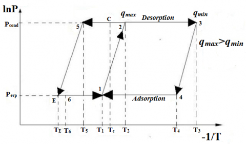
The basic adsorption refrigeration cycle consists of four components adsorber/desorber bed, condenser, expansion valve and evaporator. It is a combination of four thermodynamic processes, two are for desorption and two are for adsorption. As per Figure 1, processes 1-2 and 2-3 are related to desorption. In the process 1-2, the adsorber bed (consider as closed system) is heated by an external energy source (solar/waste heat), the temperature and pressure of adsorbate which is adsorbed inside the adsorbent, is continuously increased up to point 2 and no desorption occurs in this process. The mass concentration of adsorbate (q kg of adsorbate/kg of adsorbent) in adsorbent remains constant, so it is considered as isosteric process. After continuous heating when the pressure of adsorbate reaches to condenser pressure Pc, the valve between adsorber bed and condenser is opened. Then desorption of adsorbate starts at constant pressure and continues till the adsorbate temperature reaches a maximum regeneration temperature T3. This process is shown 2-3 in Figure 1. In this process, due to the continuous desorption of adsorbate, the concentration of adsorbate in adsorbent decreases from a maximum level qmax to a minimum level qmin. Simultaneously in process 2-5, the desorbed adsorbate is condensed in a condenser and collects in receiver. In process 5-6, adsorbate goes through the expansion valve and creates refrigeration effect in evaporator.
Figure 1. Basic adsorption refrigeration cycle [3]
As adsorption refrigeration processes are intermittent so next processes (process 3-4 and 4-1) are related to adsorption of adsorbate in adsorbent. Process 3-4 (isosteric process), in which the adsorber bed is cooled up to temperature T4 with the help of some external cooling source. Due to that adsorbate temperature and pressure reduces up to evaporator pressure Pe. The next process 4-1(isobaric process) in which the bed temperature is further reduces up to T1 and adsorption is started. The valve between evaporator and adsorber is opened. From evaporator low pressure and low temperature adsorbate enters to the adsorber bed. The Mass concentration of adsorbate in adsorbent increases from a minimum level qmin to a maximum level of qmax [3]. The difference in amount of adsorption before and after adsorption (qmax-qmin) is known as cyclic amount of adsorbate (.q). The performance of the system is depending upon this .q amount of adsorbate.
2.2 Geometry
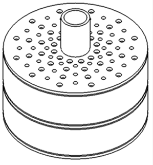
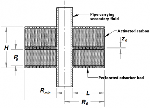
The study is performed on a finned tube adsorber of geometry shown in the Figure 2. As shown in the figure, activated carbon is packed in the compartments formed in between two consecutive fins. The refrigerant vapour enters the adsorber through the perforated finned surface. The vapour then moves through the bed to reach the inner portions. The refrigerant is assumed to be adsorbed in vapour phase only. The adsorption in the bulk as well as pores of the particles is considered. As adsorption phenomenon is exothermic in nature, cold secondary fluid (water) is circulated through the pipes to carry away the heat of adsorption thus maintaining the temperature inside the packed bed.
Similarly, during desorption part of cycle, hot secondary fluid is circulated to release methanol to the perforated bed from activated carbon packed bed. Hence, for continuous supply of refrigerant to be maintained with in the refrigeration cycle, multiple beds can be used by introducing simultaneous adsorption and desorption part of cycle in different beds. This also leads to reduction of the idle time in the refrigeration cycle. Freundlich isotherm equation is used to model adsorption of methanol in activated carbon and the following equation was developed [23].
${{q}^{*}}=K{{\left( \frac{P}{{{P}_{s}}} \right)}^{{}^{1}/{}_{n}}}$ (1)
$K=\varepsilon \frac{\rho }{{{\rho }^{*}}}$ (2)
The difference in amount of adsorption before and after adsorption has been calculated using the following equation [11].
$\Delta q=K\left[ {{\left( \frac{{{P}_{s}}\left( {{T}_{ev}} \right)}{{{P}_{s}}\left( {{T}_{a}} \right)} \right)}^{{}^{1}/{}_{n}}}-{{\left( \frac{{{P}_{s}}\left( {{T}_{cond}} \right)}{{{P}_{s}}\left( {{T}_{reg}} \right)} \right)}^{{}^{1}/{}_{n}}} \right]$ (3)
Figure 2. Isometric and sectional view of finned tube adsorber
2.3 Governing equation
The governing equation is derived by considering mass transfer in particle, based on solid – diffusion model of intra particle diffusion in particles [11]. The particles in the bed were assumed to be spherical in shape.
$\frac{\partial {{q}_{p}}}{\partial t}=D\left( \frac{{{\partial }^{2}}{{q}_{p}}}{\partial {{r}^{2}}}+\frac{2}{r}\frac{\partial {{q}_{p}}}{\partial r} \right)$ (4)
The average value of adsorption amount can be expressed using the following equation:
${{q}_{{{p}_{ave}}}}=\underset{0}{\overset{{{r}_{0}}}{\mathop \int }}\,{{r}^{2}}qdr$ (5)
The mass transfer in bed was modeled with assumptions that the particles are uniformly distributed in the bed and refrigerant is adsorbed in the vapor phase:
$\varepsilon \frac{\partial \rho_{b}}{\partial t}+(1-\varepsilon) \frac{\partial q_{p_{a v e}}}{\partial t}=\frac{K}{\mu \rho_{0}}\left[\begin{array}{l}
\rho_{b}\left(\begin{array}{l}
\frac{\partial^{2} \rho_{b}}{\partial R^{2}}+\frac{1}{R} \frac{\partial \rho_{b}}{\partial R} \\
+\frac{\partial^{2} \rho_{b}}{\partial Z^{2}}
\end{array}\right) \\
+\left(\frac{\partial \rho_{b}}{\partial R}\right)^{2}+\left(\frac{\partial \rho_{b}}{\partial Z}\right)^{2}
\end{array}\right]$ (6)
2.4 Initial conditions (at t = 0.0)
Adsorption process:
For solid diffusion model of intra particle diffusion of spherical particles:
$q_{p i}=q_{p a} \text { For } 0<\boldsymbol{r}<\boldsymbol{r}$ (7)
For mass transfer in the bed
$\rho_{b i}=\rho_{p a} \text { For } \boldsymbol{R}_{\boldsymbol{m i n}}<\boldsymbol{R}<\boldsymbol{R}_{0}, 0<\boldsymbol{Z}<\boldsymbol{Z}_{0}$ (8)
Desorption process:
For solid diffusion model of intra particle diffusion of spherical particles:
$q_{p i}=q_{p d}$ For 0 < r < r0 (9)
For mass transfer in the bed
$\rho_{b i}=\rho_{p d}$ For Rmin<R<R0, 0<Z<Z0 (10)
2.5 Boundary conditions
For adsorbent particles:
At r = 0;
$\frac{\partial q_{p}}{\partial r}=0$ (11)
At r = r0;
qp = qpmax (12)
For mass transfer in the bed
At R = Rmin, 0 < Z < Z0;
$\frac{\partial \rho_{b}}{\partial R}=0$ (13)
At R = R0, 0 < Z < Z0;
$\rho_{b}=\rho_{b i}$ (14)
At Z = 0, Z0, Rmin < R < R0
$\frac{\partial \rho_{b}}{\partial Z}=0$ (15)
2.6 Solution methodology
Assuming i to be the variation along radial direction of adsorbent particle, j being the variation along radial direction of adsorber, m being the variation along axial direction of adsorber and k being the variation of time the differential terms in Eq. (4) and Eq. (6) were discretized using the finite difference method [24] and the following difference equations were obtained respectively:
$\frac{\partial\left(q_{p}\right)_{k}^{i}}{\partial t}=D\left[\begin{array}{l}
\left(\frac{\left(q_{p}\right)_{k}^{i+1}-2\left(q_{p}\right)_{k}^{i}+\left(q_{p}\right)_{k}^{i-1}}{d R^{2}}\right) \\
+\frac{2}{R^{i}}\left(\frac{\left(q_{p}\right)_{k}^{i+1}-\left(q_{p}\right)_{k}^{i-1}}{2 d R}\right)
\end{array}\right]$ (16)
$\varepsilon \frac{\partial\left(\rho_{b}\right)_{k}^{j, m}}{\partial t}+(1-\varepsilon) \frac{\partial q_{a v e}}{\partial t}=\frac{K}{\mu \rho_{0}}\left(\left(\rho_{b}\right)_{k}^{j, m} A+B\right)$ (17)
where
$A=\left[ \left( \begin{align}& \frac{\left( {{\rho }_{b}} \right)_{k}^{j+1,m}-2\left( {{\rho }_{b}} \right)_{k}^{j,m}+\left( {{\rho }_{b}} \right)_{k}^{j-1,m}}{d{{R}^{2}}}+ \\& \frac{1}{{{R}^{j}}}\frac{\left( {{\rho }_{b}} \right)_{k}^{j+1,m}-\left( {{\rho }_{b}} \right)_{k}^{j-1,m}}{2dR}+ \\ & \frac{\left( {{\rho }_{b}} \right)_{k}^{j,m+1}-2\left( {{\rho }_{b}} \right)_{k}^{j,m}+\left( {{\rho }_{b}} \right)_{k}^{j,m-1}}{d{{Z}^{2}}} \\\end{align} \right) \right]$$B=\left[ \begin{align} & {{\left( \frac{\left( {{\rho }_{b}} \right)_{k}^{j+1,m}-\left( {{\rho }_{b}} \right)_{k}^{j-1,m}}{2dR} \right)}^{2}}+ \\ & {{\left( \frac{\left( {{\rho }_{b}} \right)_{k}^{j,m+1}-\left( {{\rho }_{b}} \right)_{k}^{j,m-1}}{2dZ} \right)}^{2}} \\\end{align} \right]$
These unsteady state equations were solved using explicit scheme in the time domain [24].
2.7 Performance calculation of the system
COP of the system is defined as the ratio of adsorbed heat by the refrigerant in the evaporator to the net heat supplied to the system. The COP of this system is given by:
$C O P=\frac{Q_{e}}{Q_{g}}$ (18)
where, $Q_{e}$ is the heat adsorbed by the refrigerant from the evaporator and $Q_{g}$ is the net heat supplied to the system during desorption process and is given by as follows.
${{Q}_{e}}={{m}_{rg}}\left( {{h}_{1}}-{{h}_{3}} \right)$
where, $h_{1} \text { and } h_{3}$ are the enthalpy of refrigerant methanol at the exit and inlet of evaporator respectively.
$m_{r g}$ is the total mass of refrigerant methanol flow through the evaporator and is given by:
${{m}_{rg}}={{m}_{a}}\times \Delta q$
and
${{Q}_{g}}=\left[ \begin{align} & {{m}_{a}}{{C}_{pa}}d{{T}_{a}}+\left( {{m}_{ri}}-{{m}_{rg}} \right){{C}_{pr}}d{{T}_{r}}+ \\ & {{m}_{rg}}\left( {{h}_{2}}-{{h}_{1}} \right)+{{m}_{m}}{{C}_{pm}}d{{T}_{m}}+{{m}_{rg}}{{h}_{sg}} \\\end{align} \right]$
where, $h_{2} \text { and } h_{1}$ are the enthalpy of refrigerant methanol at the exit and inlet of adsorber bed respectively.
Specific cooling power (W/kg) is define as the cooling effect produced per kg mass of the adsorbent.
$S C P=\frac{Q_{e}}{M_{\text {ads }}\quad t_{\text {cycle }}}$ (19)
mads is the mass of adsorbent (Activated carbon) in kg and tcycleis the total cycle time of the system.
Refrigeration effect (kJ/kg):
$R E=\frac{Q_{e}}{M_{a d s}}$ (20)
In the present work, the amount adsorbed and regenerated from the bed was calculated for different regeneration temperatures and evaporator temperatures. The regeneration temperature was varied from 353 K to 393 K while the evaporator temperature was varied from 268 K to 283 K. The study is limited to 393 K regeneration temperature as the system is designed to utilize low grade energy such solar and waste heat sources and achieving a temperature beyond 393 K is difficult.
The numerical values of system geometries and properties are L= 0.81 m, H=0.4 m, P0=0.175 m, Z0=0.025 m, R0 = 0.9 m, ρ* = 360 kg/m3, ϵp = 0.6 and ρp =271.5 kg/m3.
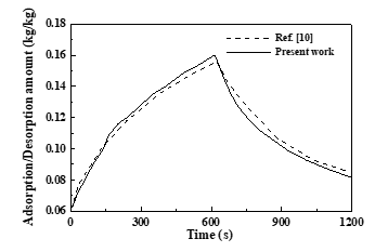
The theoretical model, thus developed into a computational code, is validated with benchmark results [10] for silica gel–water adsorption refrigeration system. It was observed that the results from the proposed model showed strong agreement with those from reference with an error of within 5% as plotted in Figure 3. Hence the model can be considered valid for an adsorption refrigeration system working with the same principle, that is, physical adsorption.
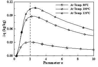
In Figure 4 the capacity of adsorption of methanol (∆q) is plotted against parameter n as given in equation 3 for different regeneration temperature. It is observed that there exists an optimum value of n for each regeneration temperature at which the capacity of adsorption of methanol reaches the maximum. The plot of Δq against n shown in Figure 4 yields an optimum n value for activated carbon- methanol. It is also observed that as regeneration temperature is increased, ∆q also increases due to the increase in saturation pressure corresponding to each regeneration temperature.
Figure 3. Validation of the proposed model
Figure 4. Variation of Δq with parameter n
Figure 5. Variation of adsorption capacity (q*) with temperature
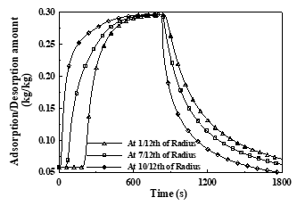
Figure 6. Adsorption/desorption along radius at Treg = 393K, Tev = 283K
Hence, using nopt = 2 and saturation pressure obtained from methanol property tables, Eq. (1) is solved for different temperatures and the variation of adsorption with adsorption temperature is plotted in Figure 5. It is observed from the figure that with increase in adsorption temperature, the adsorption capacity decreases keeping evaporator, condenser and adsorber temperatures constant. It is further observed that for a given adsorption temperature, adsorption capacity increases with increase in evaporator temperature. The variation of adsorption/desorption amount with time at various points along the radial direction was calculated and plotted in Figure 6. The legends in the plots represent the adsorption/desorption amount at 1/12th, 7/12th and 10/12th locations along the adsorber radius. It is also evident from the figure that adsorption at any given time initiates from the periphery and proceeds towards the root of the adsorbent. From the simulation, an optimum cycle time of approximately 1800 seconds was obtained. This is the time needed to complete one complete cycle of adsorption and desorption.
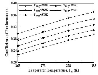
It is also evident that the time of adsorption and desorption are almost equal over a total span of optimum cycle. The reason may be attributed to the fact that the amount being evaporated and hence being adsorbed and getting regenerated increases with increase in evaporator temperature. However, the evaporator temperature cannot be arbitrarily increased to increase the performance as it depends on the temperature to be maintained in the desired space to be cooled. In Figure 7, the dependence of COP on evaporator temperature is plotted. The COP of proposed system is observed to increase with increase in evaporator temperature.
Figure 7. Variation of COP with evaporator temperature
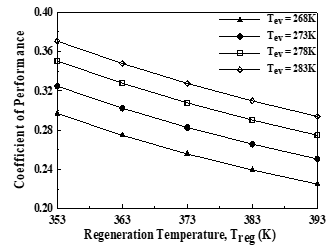
Figure 8. Variation of COP with regeneration temperature
In Figure 8, the variation of COP with regeneration temperature is plotted. The COP of the proposed system is reported to decrease with increase in regeneration temperature since the heat input needed to attain a particular regeneration temperature increases with increase in regeneration temperature. The COP is a measure of performance which depends on the amount of heat input needed to produce a particular refrigeration effect. Hence the COP, which is inversely proportional to heat input, decreases with increase in regeneration temperature.
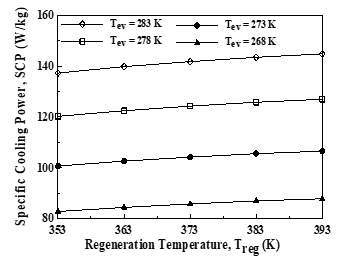
The variation of SCP with regeneration temperature is shown in Figure 9. It is observed to increase with increase in regeneration temperature but the variation was not much significant which shows that regeneration temperature has less effect on the SCP of this system.
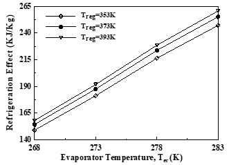
In Figure 10, the refrigeration effect is plotted against evaporator temperature. It is observed that the variation of refrigeration effect is more significant with evaporator temperature.
Figure 9. Variation of SCP with regeneration temperature
Figure 10. Variation of Refrigeration effect with evaporator temperature
The adsorption amount depends on evaporator temperature and adsorbent bed temperature while the amount of regeneration depends on regeneration temperature. A maximum adsorption capacity of 0.2959 kg/kg was observed at an evaporator temperature of 283 K and regeneration temperature of 353 K. COP of an adsorption refrigeration system has inverse relation with regeneration temperature if the heat source is not kept constant. It was also found that the COP increases with evaporator temperature but it cannot be increased arbitrarily to increase the performance as it depends on the temperature to be maintained in the desired space to be cooled. Normally for cold storage, an evaporator temperature of -5℃ to 5℃ is preferred depending on the food to be stored and for air conditioning a temperature of 10℃ is preferred. A highest COP of 0.3706 was obtained at a regeneration temperature of 353 K and evaporator temperature of 283 K. The SCP of the proposed system is found to increase with increase in regeneration temperature but the variation is not much significant which shows that regeneration temperature has less effect on the SCP of proposed system. It is also observed that the variation of SCP is more significant with the evaporator temperature. It increases with increase in evaporator temperature. The highest SCP of 144.8 W/kg was obtained at a regeneration temperature of 393 K and evaporator temperature of 283 K. Refrigerating effect was also found to increase with both evaporator temperature and regeneration temperature and showed a maximum of 260.665 kJ/kg at a regeneration temperature of 393 K and evaporator temperature of 283 K. The proposed system of activated carbon-methanol working pair is, thus, reported to be well suited for air conditioning system where the evaporator temperature is around 283 K.
The authors gratefully acknowledge the support of the Department of Mechanical Engineering, Faculty of Mechanical and Chemical Engineering, National institute of technology Raipur, India.
|
D |
Intra-particle diffusivity |
|
h |
Enthalpy (kJ/kg) |
|
K |
Constant |
|
M |
Mass of adsorbent (kg) |
|
mrg |
Mass of adsorbate/Refrigerant (kg) |
|
n |
Constant |
|
P |
Pressure (Pa) |
|
qp |
Amount of adsorption in adsorbent particle (kg/kg) |
|
q* |
Equilibrium amount of adsorption (kg/kg) |
|
r |
Adsorbent particle radius (m) |
|
R |
Adsorber bed radius (m) |
|
t |
Time (s) |
|
T |
Temperature (K) |
|
Z |
Height of adsorber bed (m) |
|
Greek symbols |
|
|
ρv |
Density of adsorbate vapor phase (kg/m3) |
|
ρb |
Density of adsorbate in bed (kg/m3) |
|
ρ* |
Density of adsorbent (kg/m3) |
|
ε |
Porosity |
|
Subscripts |
|
|
a |
adsorber |
|
ave |
average |
|
b |
bed |
|
cond |
condenser |
|
evp |
evaporator |
|
min |
minimum |
|
max |
maximum |
|
o |
outer |
|
p |
particle |
|
reg |
regeneration |
|
rg |
refrigerant |
|
s |
saturation |
[1] Sah, R.P., Choudhury, B., Das, R.K., Sur, A. (2017). An overview of modelling techniques employed for performance simulation of low-grade heat operated adsorption cooling systems. Renewable and Sustainable Energy Reviews, 74: 364-376. https://doi.org/10.1016/j.rser.2017.02.062
[2] Faizan, S., Sultan, M., Miyazaki, T., Saha, B.B. (2020). Recent updates on the adsorption capacities of adsorbent-adsorbate pairs for heat transformation applications. Renewable and Sustainable Energy Reviews, 119: 109630. https://doi.org/10.1016/j.rser.2019.109630
[3] Soni, P., Gaba, V.K. (2019). Comparative analysis of silica-gel/water and zeolite/water pair on adsorption refrigeration system. Journal of Physics: Conference Series, 1240: 012067. https://doi:10.1088/1742-6596/1240/1/012067
[4] Hu, Y.H., Ruckenstein, E. (2006). Applicability of Dubinin–Astakhov equation to CO2 adsorption on single-walled carbon nanotubes. Chemical Physics Letters, 425(4-6): 306-310. https://doi.org/10.1016/j.cplett.2006.05.059
[5] Curran, H.M. (1977). Coefficient of performance for solar-powered space cooling systems. Solar Energy, 19(5): 601-603. https://doi.org/10.1016/0038-092X(77)90121-9
[6] Sur, A., Pandya, S., Sah, R.P., Kotecha, K., Narkhede, S. (2020). Influence of bed temperature on performance of silica gel/methanol adsorption refrigeration system at adsorption equilibrium. Particulate Science and Technology, 1-8. https://doi.org/10.1080/02726351.2020.1778145
[7] Suzuki, M., Sakoda, A. (1983). Fundamental study on solar powered adsorption cooling system. Journal of Chemical Engineering of Japan, 17(1): 52-57. https://doi.org/10.1252/jcej.17.52
[8] Wang, Q., Gao, X., Xu, J.Y., Maiga, A.S., Chen, G.M. (2012). Experimental investigation on a fluidized-bed adsorber/desorber for the adsorption refrigeration system. International Journal of Refrigeration, 35(3): 694-700. https://doi.org/10.1016/j.ijrefrig.2011.05.020
[9] Zhao, Y., Hu, E., Blazewicz, A. (2012). Dynamic modelling of an activated carbon–methanol adsorption refrigeration tube with considerations of interfacial convection and transient pressure process. Applied Energy, 95: 276-284. https://doi.org/10.1016/j.apenergy.2012.02.050
[10] Ji, X., Li, M., Fan, J., Zhang, P., Luo, B., Wang, L. (2014). Structure optimization and performance experiments of a solar-powered finned-tube adsorption refrigeration system. Applied Energy, 113: 1293-1300. https://doi.org/10.1016/j.apenergy.2013.08.088
[11] Li, L., Kubota, M., Watanabe, F., Kobayashi, N., Hasatani, M. (2004). Optimum design of a fin-type silica gel tube module in the silica gel/water adsorption heat pump. Journal of Chemical Engineering of Japan, 37(4): 551-557. https://doi.org/10.1252/jcej.37.551
[12] Hong, S.W., Ahn, S.H., Kwon, O.K., Chung, J.D. (2015). Optimization of a fin-tube type adsorption by design of experiment. International Journal of Refrigeration, 49: 49-56. https://doi.org/10.1016/j.ijrefrig.2014.09.022
[13] Liu, Y., Leong, K.C. (2006). Numerical study of a novel cascading adsorption cycle. International Journal of Refrigeration, 29(2): 250-259. https://doi.org/10.1016/j.ijrefrig.2005.05.008
[14] Leong, K.C., Liu, Y. (2004). Numerical modeling of combined heat and mass transfer in the adsorbent bed of a zeolite/water cooling system. Applied Thermal Engineering, 24(16): 2359-2374. https://doi.org/10.1016/j.applthermaleng.2004.02.014
[15] Marlinda, A., Uyun, S., Miyazaki, T., Ueda, Y., Akisawa, A. (2010). Performance analysis of a double-effect adsorption refrigeration cycle with a silica gel/water working pair. Energies, 3(11): 1704-1720. https://doi.org/10.3390/en3111704
[16] Deshmukh, H., Maiya, M.P., Murthy, S.S. (2015). Continuous vapour adsorption cooling system with three adsorber beds. Applied Thermal Engineering, 82: 380-389. https://doi.org/10.1016/j.applthermaleng.2015.01.013
[17] Sur, A., Das, R.K. (2017). Experimental investigation on waste heat driven activated carbon‑methanol adsorption cooling system. Journal of the Brazilian Society of Mechanical Sciences and Engineering, 39(7): 2735-2746. https://doi.org/10.1007/s40430-017-0792-y
[18] Chekirou, W., Boukheit, N., Kerbache, T. (2007). Numerical modelling of combined heat and mass transfer in a tubular adsorber of a solid adsorption solar refrigerator. Revue des Energies Renouvelables, 10(3): 367-379.
[19] Abd-Elhady, M.M., Hamed, A.M. (2020). Effect of fin design parameters on the performance of a two-bed adsorption chiller. International Journal of Refrigeration, 113: 164-173. https://doi.org/10.1016/j.ijrefrig.2020.01.006
[20] Sur, A., Sah, R.P., Pandya, S. (2020). Milk storage system for remote areas using solar thermal energy and adsorption cooling. Materials Today: Proceedings, 28(3): 1764-1770. https://doi.org/10.1016/j.matpr.2020.05.170
[21] Zhao, C., Wang, Y., Li, M., Zhao, W. (2020). Experimental study of a solar adsorption refrigeration system integratedwith a compound parabolic concentrator based on an enhanced masstransfer cycle in Kunming, China. Solar Energy, 195: 37-46. https://doi.org/10.1016/j.solener.2019.11.056
[22] Alelyani, S.M., Bertrand, W.K., Zhang, Z., Phelan, P.E. (2020). Experimental study of an evacuated tube solar adsorption cooling module and its optimal adsorbent bed design. Solar Energy, 211: 183-191. https://doi.org/10.1016/j.solener.2020.09.044
[23] Chihara, K., Suzuki, M. (1983). Air drying by pressure swing adsorption. Journal of Chemical Engineering of Japan, 16(4): 293-299. https://doi.org/10.1252/jcej.16.293
[24] Patankar, S.V. (1998). Numerical Heat Transfer and Fluid Flow. Hemisphere Publishing Corporation, Washington-New York-London. McGraw Hill Book Company, New York. https://doi.org/10.1002/cite.330530323