Mohammad Mazidi Sharfabadi* | Parham Mobadersani | Leila Nourpour
© 2021 IIETA. This article is published by IIETA and is licensed under the CC BY 4.0 license (http://creativecommons.org/licenses/by/4.0/).
OPEN ACCESS
In this study, the effect of the vortex generators on the heat transfer and flow characteristics in a rectangular channel is investigated numerically by finite volume method. The governing equations are discretized using QUICK scheme. The numerical results are validated against published experimental data. In this paper, the effects of the winglet aspect ratio and the distance between the vertices of the winglets on the heat transfer and hydrodynamic characteristics of the flow are surveyed. In addition, to achieve the optimum amount of heat transfer, it is important to know the proper arrangement of the triangular winglet pairs as well as their suitable position. Therefore, the appropriate values of the longitudinal and transverse pitch are presented in this paper. The results show that the winglet with the aspect ratio of 1.75 has the best thermal and hydrodynamic performance. Furthermore, the transverse pitch of 1.24 causes 6.5% growth in the average Nusselt number.
vortex generator, winglet, aspect ratio, transverse pitch, longitudinal pitch, CFD
Compact plate heat exchangers are widely used in the industries of petroleum, petrochemical, automotive, air conditioning, refrigeration and data center cooling systems [1, 2]. The heat transfer performance of conventional heat exchanger devices can be substantially improved by a number of heat transfer enhancement techniques [3]. Among the most effective ways to increase the efficiency of these heat exchangers, increasing the rate of turbulence and developing turbulent flow, play an important role. Optimizing and increasing the performance of the heat exchangers according to the importance of reducing energy consumption and costs has many technical, economic and environmental advantages.
In this context, many researchers have tried to use different types of vortex generators to investigate the heat transfer in the heat exchangers. In 1969, Jonson and Joubert [4] reported the first results about the effects of longitudinal vortices on the heat transfer. They studied the effect of one row of triangular winglet on the drag and heat transfer of a cylinder that was perpendicular to the airflow. They found that the drag force on the cylinder was decreased because of the delayed separation due to the presence of longitudinal vortices and accordingly the heat transfer was increased. Russell et al. [5] developed plate fin surfaces on which local rectangular vortex generators produce a set of contra-rotating vortices between the fins. They showed that small angles of attack have disappointing performance. Turk and Junkhan [6] investigated a row of rectangular winglets so that the heat transfer was decreased at the back of the winglet and was increased continuously at the downstream. Chen et al. [7] studied the influence of triangular vortex generators on the thermal performance of elliptical fin-tubes. They solved the Navier-Stokes and energy equations by the use of finite volume method. They found that the presence of delta winglet pairs, intensified the pressure drop and the winglet had the best thermal performance, when its angle of attack and aspect ratio were equal to 30o and 2, respectively. Wang et al. [8] used triangular and annular vortex generators in their experimental investigation of fin-tube heat exchangers and concluded that the triangular types are more efficient than the annular ones. Pesteei et al. [9] measured the heat transfer coefficient in fin-tube heat exchangers by the use of triangular winglets. They determined the best location to install the barriers around the tubes. Biswas et al. [10] studied numerically and experimentally laminar flow through the channel that has one triangular winglet on the one of its walls. The main objective of their work is to determine the optimum angle of attack. Hiravennavar et al. [11] surveyed the influence of triangular winglets on the flow characteristics and the heat transfer rate of the laminar flow. They found that a pair of winglet is more efficient than the single winglet. Yang et al. [12] measured the heat transfer rate of a channel with triangular winglets by the use of thermo-chromatic liquid crystal method. They changed the angle of attack in the common flow down and up cases and concluded that putting barriers in the common flow down is more efficient. Wu and Tao [13] simulated the convection heat transfer in the channel with the laminar flow through it. They studied the effect of holes created by punching and concluded that in this case the pressure drop is decreased and the rate of heat transfer is increased. Soltanipour et al. [14] investigated heat transfer and pressure drop in compact heat exchangers using vortex generators. They did their calculations at the different angles of attack and investigated the effect of the vortices that occur on the fin. Promvonge et al. [15] studied experimentally the combined effects of ribs and vortex generators on the forced convection heat transfer and the pressure drop through a channel with constant heat flux. The results showed the significant influences of the combination of the ribs and vortex generators on the heat transfer rate and the friction losses. Wu and Tao [16] studied experimentally and numerically the flow characteristics in a channel with a triangular vortex generator and investigated the angle of attack and the Reynolds number effects on heat transfer rate. Chomdee and Kiatsiriroat [17] used the triangular winglets to increase heat transfer in electrical circuits. Ferrouillat et al. [18] surveyed the effects of vortex generators and rectangular winglets. The analysis was done based on k-ε model and the influences of different angles of attack and the Reynolds numbers on the Nusselt number and the pressure drop were studied. Luo et al. [19] studied numerically the effect of delta winglet vortex generators and the combination of delta vortex generators and obstacles on a solar receiver heat exchanger. They revealed that the use of the delta winglet vortex generators induced pressure gradients on more than one direction and thus vortices were generated. Thus, the flow velocity is increased. In addition, they concluded that using the semi-cylinder ribs would lead to the highest heat transfer rate. Salviano et al. [20] studied numerically the optimum designs of the delta winglet vortex generators in compact heat exchangers. They concluded that by using non-symmetric delta winglet vortex generators, the highest heat transfer is obtained. Zhou and Ye [21] compared experimentally the performance of the vortex generators in the laminar, transitional and turbulent flow regimes. Their results showed that delta winglet pair was the best in laminar and transitional flow region, while curved trapezoidal winglet pair had the best thermohydraulic performance in fully turbulent region. Lu and Zhou [22] carried out a 3D numerical simulation in a channel with a pair of vortex generators with the Reynolds number varying from 700 up to 26500. In addition, they investigated the effect of the vortex generators with and without holes on their surfaces. They concluded that the vortex generators with the punched holes provide higher heat transfer and lower flow resistance. Chen et al. [23] conducted some experiments on the pressure drop and the heat transfer in micro-channels equipped with vortex generators. They found that the heat transfer was enhanced significantly. Gong et al. [24] enhanced heat transfer by the use of curved vortex generators in the wake region.
In the present work, the performance of triangular winglet pair vortex generators on the heat transfer in a rectangular channel is investigated. The effect of the winglet aspect ratio is studied and different winglet pair arrangements and positions are examined.
The winglets are arranged on a fin that is placed in the middle of the channel according to the experimental model [16]. Flow in the channel is generally laminar, because of low-speed fluid flow and the small size of the generators. Air is considered as an incompressible fluid with constant physical properties, and it is also assumed to be three dimensional, steady and without viscous dissipation.
2.1 The governing equations
The governing equations of flow, including conservation of mass, momentum and energy, are expressed as follows:
$\frac{\partial u_{\mathrm{i}}}{\partial \mathrm{x}_{\mathrm{i}}}=0$ (1)
$\frac{\partial\left(u_{i} u_{j}\right)}{\partial \mathrm{x}_{\mathrm{i}}}=\frac{\partial}{\partial \mathrm{x}_{\mathrm{i}}}\left(v \frac{\partial \mathrm{u}_{\mathrm{j}}}{\partial \mathrm{x}_{\mathrm{i}}}\right)-\frac{1}{\rho} \frac{\partial \mathrm{P}}{\partial \mathrm{x}_{\mathrm{j}}}$ (2)
$\frac{\partial\left(u_{i} T\right)}{\partial \mathrm{x}_{\mathrm{i}}}=\frac{\partial}{\partial \mathrm{x}_{\mathrm{i}}}\left(\alpha \frac{\partial \mathrm{T}}{\partial \mathrm{x}_{\mathrm{i}}}\right)$ (3)
2.2 The geometry of the model
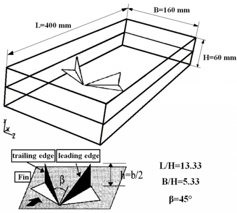
The model that was investigated by Wu and Tao [16] is used as a reference case in the present work. The winglets and the channel dimensions can be seen in Figure 1.
Figure 1. View of the based model
2.3 The boundary conditions
The inlet boundary condition is defined as velocity inlet. Air with the uniform temperature and velocity enters the channel in the direction of x axis. In the present work, outlet boundary condition is pressure outlet. The temperature of the fluid in the inlet of the channel is assumed to be known and it is equal to 20 °C. No-slip condition is imposed on the upper and lower walls of the channel. All components of the velocity will be equal to zero, by imposing this boundary condition. The thickness of the upper and lower walls and the heat dissipation is negligible. According to the experimental model, the constant heat flux of 35 W is applied to the surface of the fin placed in the middle of the channel. The vortex generators used in this study are in the shape of delta winglet pairs. According to the previous studies [16, 25, 26] triangular winglets show the best performance in this arrangement.
2.4 Model gridding
As it can be seen in Figure 1, the computational region is three-dimensional and the channel is separated to two different volumes by the internal fin. The geometry of the model is rather complicated, because the vortex generators have triangular shape and they are punched to the fin plate. The channel volume is divided into 90 to 120 smaller volumes. For meshing the computational domain, unstructured grids are generated. About 8× 10⁵ to 1.3× 10⁶ meshes are used for the whole of computational domain in different cases.
The solution was obtained based on the SIMPLE algorithm. The momentum and energy equations were discretized by QUICK scheme. To validate the computational code used in this study, several numerical simulations were carried out to reproduce the results reported by Wu and Tao [16]. The Conservation equations for the mass, momentum and energy with proper boundary conditions for the domain were solved using finite volume method.
As it can be seen in Figure 2, the results obtained from the solution of the laminar flow are more accurate than the numerical work presented by Wu and Tao [16] and they are in a good agreement with the experimental data. In addition, the results obtained using the SST turbulence model are shown in this figure. The laminar model presents valid results in this range of Reynolds numbers. Therefore, the laminar flow regime is chosen for the simulation and obtaining further results.
Figure 2. Average Nusselt number variation with the Reynolds number in a channel with vortex generators obtained from different methods
4.1 The influence of the winglet aspect ratio
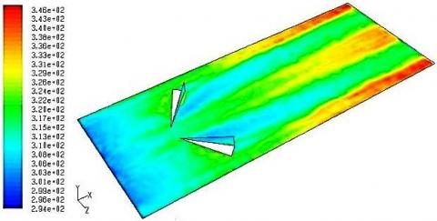
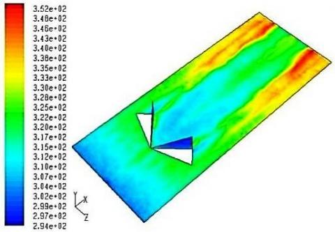
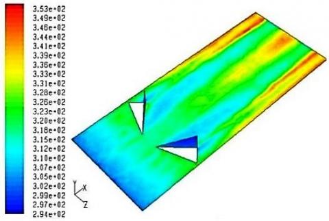
To investigate the effect of the aspect ratio on the flow field and heat transfer, delta winglet pair on the channel with different aspect ratios (Λ=1, 1.33, 1.75, 1.867, 2 and 4) are modeled. Figures 3 to 5 show the temperature contour for Re=1550 on the fin which winglets are installed on with aspect ratios of 1, 1.75 and 4, respectively.
Figure 3. Temperature contour on the fin with a triangular winglet pair for Λ=1 and Re=1550
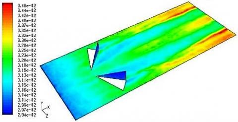
Figure 4. Temperature contour on the fin with a triangular winglet pair for Λ=1.75 and Re=1550
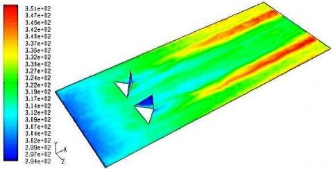
Figure 5. Temperature contour on the fin with a triangular winglet pair for Λ=4 and Re=1550
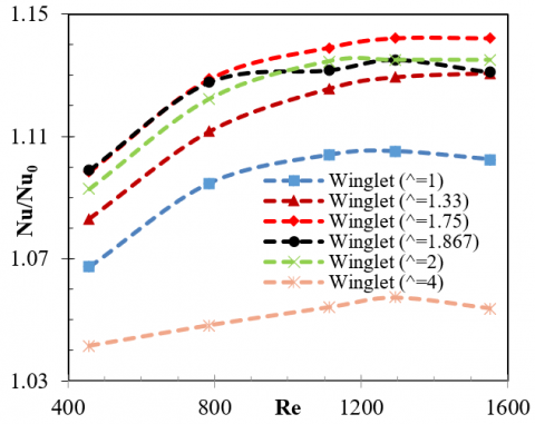
Due to small height of the winglet in low aspect ratios, they are located within the heat boundary layer. This increases the surface temperature. Increasing the aspect ratio causes the created vortices become stronger. This does not occur for the aspect ratios bigger than 2. To clear up this, the variation of the average Nusselt number ratio, Nu/Nu0, in terms of the Reynolds number for different aspect ratios is shown in Figure 6. In this figure, Nu0 is average Nusselt number over the fin without winglet.
Figure 6. Average Nusselt number ratio variations in terms of the Reynolds number for the winglets with different aspect ratios
As it is obviously clear in Figure 6, the aspect ratios between 1.5 and 2 have better results and the winglet with the aspect ratio of 1.75 has the highest Nusselt number ratio. In low Reynolds numbers, the performance of the winglets with the aspect ratio of 1.75 and 1.867 are close to each other but by increasing in the Reynolds number, the winglet with the aspect ratio of 1.75 has better thermal performance. The delta winglet pair with aspect ratio of 1.75 increases the heat transfer up to 14.2% in comparison with the smooth channel for Re=1550. This amount for the winglet with the aspect ratio of 1.867 is about 13.1%.
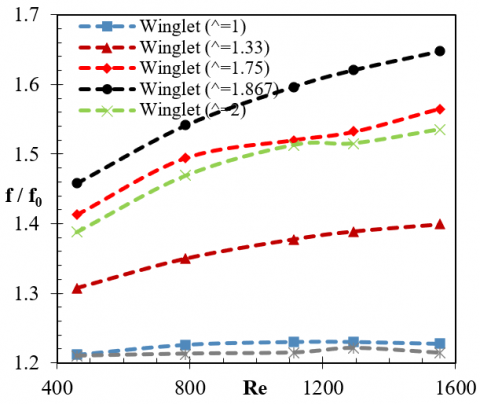
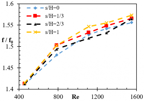
The variation of the pressure drop coefficient, f/f0, with different aspect ratios in terms of the Reynolds number is illustrated in Figure 7. In this figure, f0 is pressure drop over the fin without winglet. As it is shown by increasing the aspect ratio, the pressure drop coefficient rises, because any increase in the dimensions of the winglets causes more pressure drop in the flow. It is considerable that the winglet with the aspect ratio of 1.867 has more pressure drop in comparison with the aspect ratio of 1.75.
Figure 7. Pressure drop coefficient variation in terms of the Reynolds number for the winglets with different aspect ratios
Figure 8. Thermal performance variation in terms of the Reynolds number for the winglets with the aspect ratios of 1.75 and 1.867
The average Nusselt number ratio to pressure drop coefficient, (Nu/Nu0)/(f/f0), is used to evaluate the thermal performance of a channel with the vortex generator in comparison with a smooth channel. Figure 8 shows the variation of this value for the aspect ratios of 1.75 and 1.867. As the Reynolds number increases, the thermal performance ratio reduces because of the increment of the pressure drop. The results show that the winglet with the aspect ratio of 1.75 has better thermal performance.
4.2 The effect of winglet vertices distance
Figures 9 and 10 show the temperature contours on the fin that a pair of triangular winglets are punched on it with different distances between their vertices for Re=1293.
By comparing the contours of temperature on the fin, it is concluded that the distance between the vertices of the winglets does not influence the intensity of the vortices generated by them but it can change their focus. This means that the area of the fin, which is influenced by the vortices, is almost unchanged and when the winglets approach each other, only the generated vortices become closer. It is found that the maximum surface temperature value has not been changed and only the locus where the maximum temperature happens is displaced. Therefore, the average Nusselt number on the fin surface has been investigated to choose an appropriate vertex distance in order to achieve higher heat transfer.
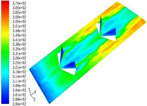
Figure 9. Temperature contours on the fin with a triangular winglet pair for Re=1293 and S/H=0
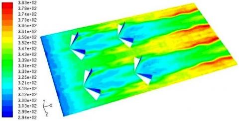
Figure 10. Temperature contours on the fin with a pair of triangular winglet for Re=1293 and S/H=1
Figure 11 shows the variation of the Average Nusselt number ratio against the distance between the vertices of the winglets. In this figure, the distance between winglet vertices is defined as S. It turns out that further increment in heat transfer will be achieved in comparison with smooth channel, when the winglets are sticking together and the distance between their vertices is zero. This increment will be greater if the Reynolds number rises. Consequently, for increasing the heat transfer rate, S is chosen equal to zero. Another important aspect is a new rise of the Nusselt number at S=30 mm which can be related to the distribution of the vortices across the channel.
Figure 11. Average Nusselt number ratio variation with respect to the distance of winglet vertices at different Reynolds numbers
Figure 12. Pressure drop coefficient variation with the Reynolds number for different distance of winglet vertices
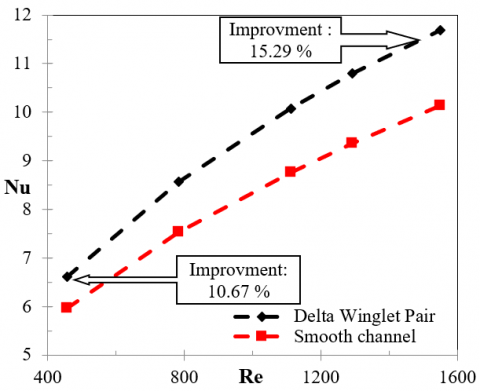
Figure 13. Average Nusselt number variation with the Reynolds number for the channels with and without delta winglet pair (Λ=1.74 and S=0)
The variation of the pressure drop coefficient in the channel with respect to the Reynolds number for different distances of vertices is shown in Figure 12. The lowest pressure drop is obtained when S=0. As the winglets become farther from each other, the pressure drop increases. It should be noted that, the variation of pressure drop is not too significant in different cases, because the barriers on the flow path are the same in all cases and the pressure drop is directly related to the shape of the barriers.
As Shown in Figure 13, If the delta winglet pair with the aspect ratio of 1.75 and with no distance between its vertices is used, the Nusselt number will increase 10.67% for Re=458 and 15.29% for Re=1550 in comparison with smooth channel.
4.3 Adding second row of winglet pairs
Figure 14 shows the temperature contours on the fin surface with two rows of vortex generator with triangular winglets on it.
Figure 14. Temperature contours on the fin with two rows of winglets for Re=758
As it can be observed in Figure 14, behind the second row of winglets, the fin temperature decreases significantly, that represents the effectiveness of adding the second row. In addition, maximum temperature is greatly reduced and a more uniform temperature distribution can be found on the fin by comparing Figure 14 with the temperature contours presented in sections 4.1 and 4.2.
Figure 15. Average Nusselt number variation with the Reynolds number for the channels with one or two rows of winglets
Figure 15 shows the variation of the average Nusselt number against the Reynolds number for channels with one or two rows of winglets.
It should be noted that due to the limitation associated with the channel length, the efficiency of the vortices generated by the second row could not be illustrated. As shown in Figure 15, the Nusselt number increases when the Reynolds number rises. The second row of winglets is more efficient in higher Reynolds numbers.
Figure 16 shows the local Nusselt number in terms of the dimensionless length of the channel with one or two winglet pairs for Re=1550 and along the line where the longitudinal vortices are dominated.
Figure 16. Local Nusselt number variations along the channel with one or two rows of winglet for Re=1550
As illustrated in Figure 16, the Nusselt number is reduced to zero at the point just before the winglets, due to the hole that has been created by punching winglets on the fin. In fact, at this point there is no surface for heat transfer. Small fluctuations observed in the area between two rows are due to the turbulent flow. Increasing pressure at the second row of winglets causes unfavorable pressure gradient. This leads to flow reversal.
4.4 Adding second column of vortex generator
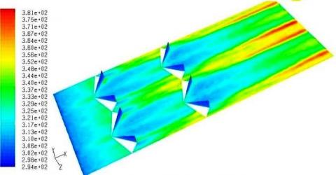
Figure 17. Temperature contour for two columns and two rows of triangular winglets pairs with transverse pitch Xt/H=2.83 for Re=785
The transverse pitch is defined as the distance between two columns of the vortex generator. If the distance between two columns becomes larger, some parts of the fin surface might not be affected by the created vortices and thus the heat transfer effective area reduces and the surface temperature rises. Figure 17 shows the temperature contour on the fin for two columns and two rows of triangular winglets pairs with transverse pitch of Xt/H=2.83 for Re=785. It is observed that the space between two columns is deprived of the effect of generated vortices, so the distance between two columns should be chosen such that the vortices influenced the entire surface of the fin.
The transverse distribution of the local Nusselt number at different sections of a channel with one column of vortex generator shows that the effect of the vortices continues to z=±0.06 m, and then the Nusselt number decreases sharply. By installing the next column at this point, the decrement in the Nusselt number is prevented. By a simple geometrical calculation, the transverse pitch, Xt/H, is obtained equal to 1.24.
Figure 18 shows the temperature contour on the fin with two columns and two rows of triangular winglet pairs by transverse pitch of Xt/H=1.24 and for Re=785. By comparing the temperature distributions on the fin shown in Figures 17 and 18, it is concluded that the surface temperature of the fin is reduced more when a transverse pitch of Xt/H=1.24 is selected, because the vortices generated by two columns become closer as they approach toward each other. An increase in the fin temperature is observed repetitively at the end of the channel. It indicates the need for the third row of the winglets because the channel is long and the vortex strength reduces at the end of it and consequently the temperature increases.
Figure 18. Temperature contour for two columns and two rows of triangular winglets pairs with transverse pitch Xt/H=1.24 for Re=785
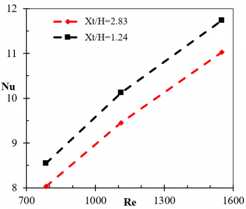
Figure 19. Average Nusselt number variation with the Reynolds number for the two channels with different transverse pitch values
Figure 19 shows the variation of the average Nusselt number with the Reynolds number for two channels with different values of transverse pitch. As mentioned before, the Nusselt number in the channel with transverse pitch of Xt/H=1.24 is 6.5% higher the values belong to Xt/H=2.83.
In this paper, the effect of triangular winglet pairs on the heat transfer and flow characteristics in a rectangular channel was investigated numerically by finite volume method. The Navier-Stokes and energy equations were discretized using QUICK scheme. The obtained numerical results were validated with the experimental data. They were in good agreement. The influence of the winglet aspect ratio was studied and different winglet pair arrangements and positions were examined.
By considering the variation of the Nusselt number with the winglet aspect ratio, it was found that the aspect ratio of 1.75 has the best thermal and hydrodynamic performance. The results showed that the heat transfer increases when the vertices of the winglets are sticking together and the ratio S/H is equal to zero. In this case, the pressure drop would be low and the Nusselt number will increase 10.67% for Re=458 and 15.29% for Re=1550 in comparison with smooth channel.
To choose an optimum longitudinal pitch size, the variation of the local Nusselt number along the channel was investigated. It was concluded that the next row of the winglet pair should be located at the point where the longitudinal vortices behind the first row is dissipated. Furthermore, the effect of the transverse pitch between two columns of vortex generator on the heat transfer was studied the results showed selecting the winglet transverse pitch of 1.24 would lead to 6.5% growth in the average Nusselt number in comparison with results obtained for transverse pitch of 2.83.
|
B |
Channel width, m |
|
f |
Pressure drop coefficient |
|
h |
Winglet height, m |
|
H |
Channel height, m |
|
L |
Channel length, m |
|
Nu |
Average Nusselt number |
|
P |
Pressure, Pa |
|
Re |
Reynolds number |
|
S |
Distance between winglet vertices, m |
|
T |
Temperature, K |
|
ui, uj |
Velocity components, m.s-1 |
|
x |
Cartesian component |
|
Xt |
Transverse pitch, m |
|
y |
Cartesian component |
|
z |
Cartesian component |
|
Greek symbols |
|
|
α |
Thermal diffusivity, m2.s-1 |
|
β |
Angle of attack, degree |
|
Λ |
Winglet aspect ratio |
|
υ |
Kinetic viscosity, m2.s-1 |
|
ρ |
Density, kg.m-3 |
[1] Deshmukh, P.W., Vedula, R.P. (2014). Heat transfer and friction factor characteristics of turbulent flow through a circular tube fitted with vortex generator inserts. International Journal of Heat and Mass Transfer, 79: 551-560. https://doi.org/10.1016/j.ijheatmasstransfer.2014.08.042
[2] Gao, T., Sammakia, B., Geer, J. (2015). Dynamic response and control analysis of cross flow heat exchangers under variable temperature and flow rate conditions. International Journal of Heat and Mass Transfer, 81: 542–553. https://doi.org/10.1016/j.ijheatmasstransfer.2014.10.046
[3] He, Y.L., Chu, P., Tao, W.Q., Zhang, Y.W., Xie, T. (2013). Analysis of heat transfer and pressure drop for fin-and-tube heat exchangers with rectangular winglet-type vortex generators. Applied Thermal Engineering, 61(2): 770-783. https://doi.org/10.1016/j.applthermaleng.2012.02.040
[4] Jonson, T.R., Joubert, P.N. (1969). The influence of vortex generators on drag and heat transfer from a circular cylinder normal to an air stream. Journal of Heat Transfer, 91(1): 91-99. https://doi.org/10.1115/1.3580126
[5] Russell, C.M.B., Jones, T.V., Lee, G.H. (1982). Heat transfer enhancement using vortex generators. Proceeding of 7th International Conference on heat transfer, Munich, West Germany, 3:283-288. https://doi.org/10.1615/IHTC7.1850
[6] Turk, A.Y., Junkhan, G.H., (1986). Heat transfer enhancement downstream of vortex generators on flat plate. Proceeding of 8th International Conference on Heat Transfer, San Francisco, USA, 6: 2903-2908. https://doi.org/10.1615/IHTC8.1450
[7] Chen, Y., Fiebig, M., Mitra, N.K. (2000). Heat transfer enhancement of finned oval tubes with staggered punched longitudinal vortex generators. International Journal of Heat and Mass Transfer, 43: 417-435. https://doi.org/10.1016/S0017-9310(99)00157-X
[8] Wang, C.C., Lo, J., Lin, Y.T, Wei C.S. (2002). Flow visualization of annular and Delta winglet vortex generators in fin-and-tube heat exchanger application. International Journal of Heat and Mass Transfer, 45(18): 3803-3815. https://doi.org/10.1016/S0017-9310(02)00085-6
[9] Pesteei, S.M., Subbarao P.M.V., Agarwal, R.S. (2005). Experimental study of the effect of winglet location on heat transfer enhancement and pressure drop in fin-tube heat exchangers. Applied Thermal Engineering, 25(11-12): 1684-1696. https://doi.org/10.1016/j.applthermaleng.2004.10.013
[10] Biswas, G., Torri, K., Fuji, D., Nishino, K. (1996). Numerical and determination of flow structure and heat transfer effects of longitudinal vortices in a channel flow. International Journal of Heat and Mass Transfer, 39(16): 3441-3451. https://doi.org/10.1016/0017-9310(95)00398-3
[11] Hiravennavar, S.R., Tulapurkara, E.G., Biswas, G. (2007). A note on the flow and heat transfer enhancement in a channel with built-in winglet pair. International Journal of Heat and Fluid Flow, 28(2): 299-305. https://doi.org/10.1016/j.ijheatfluidflow.2006.03.030
[12] Yang, J.S., Hong, C.H., Choi, G.M. (2007). Heat transfer measurement using thermochromatic liquid crystal. Current Applied Physics, 7(4): 413-420. https://doi.org/10.1016/j.cap.2006.09.027
[13] Wu, J.M., Tao, W.Q. (2008). Numerical study on laminar convection heat transfer in a rectangular channel with longitudinal vortex generators. Part A: Verification of field synergy principle. International Journal of Heat and Mass Transfer, 51(5-6): 1179-1191. https://doi.org/10.1016/j.ijheatmasstransfer.2007.03.032
[14] Soltanipour, H., Pesteei, S.M., Mirzaee I. (2009). Performance improvement and surface reduction of plain-plate heat exchangers using vortex Using Vortex Generators. Proceeding of 17th International Conference on Mechanical Engineering (ISME 2009), Tehran, Iran.
[15] Promvonge, P., Chompookham, T., Kwankaomeng, S., Thianpong, C. (2010). Enhanced heat transfer in a triangular ribbed channel with longitudinal vortex generators. Journal of Energy Conversion and Management, 51(6): 1242-1249. https://doi.org/10.1016/j.enconman.2009.12.035
[16] Wu, J.M., Tao, W.Q. (2012). Effect of longitudinal vortex generator on heat transfer in rectangular channels. International Journal of Thermal Engineering, 37: 67-72. https://doi.org/10.1016/j.applthermaleng.2012.01.002
[17] Chomdee, S., Kiatsiriroat, T. (2006). Enhancement of air cooling in staggered array of electronic modules by integrating delta winglet vortex generators. International Communications in Heat and Mass Transfer, 33(5): 618-626. https://doi.org/10.1016/j.icheatmasstransfer.2006.01.002
[18] Ferrouillat, S., Tochon, P., Garnier, C., Peerhossaini, H. (2006). Intensification of heat-transfer and mixing in multifunctional heat exchangers by artificially generated streamwise vorticity. Applied Thermal Engineering, 26(16): 1820-1829. https://doi.org/10.1016/j.applthermaleng.2006.02.002
[19] Luo, L., Wen, F., Wang, L., Sunden, B., Wang, S. (2016). Thermal enhancement by using grooves and ribs combined with delta-winglet vortex generator in a solar receiver heat exchanger. Applied Energy, 183: 1317-1332. https://doi.org/10.1016/j.apenergy.2016.09.077
[20] Salviano, L.O., Dezan, D.J., Yanagihara, J.I. (2014). Multi-objective optimization of vortex generators position and angles in fin-tube compact heat exchanger at low Reynolds number using neural network and genetic algorithm. Proceeding of the 15th International Conference on Heat Transfer, Kyoto, Japan. https://doi.org/10.1615/IHTC15.opt.009018
[21] Zhou, G., Ye, Q. (2012). Experimental investigations of thermal and flow characteristics of curved trapezoidal winglet type vortex generators. Applied Thermal Engineering, 37: 241-248. https://doi.org/10.1016/j.applthermaleng.2011.11.024
[22] Lu, G., Zhou, G. (2016). Numerical simulation on performances of plane and curved winglet type vortex generator pairs with punched holes. International Journal of Heat and Mass Transfer, 102: 679-690. https://doi.org/10.1016/j.ijheatmasstransfer.2016.06.063
[23] Chen, C., Teng, J.T., Cheng, C.H., Jin, S., Huang, S., Liu, C., Lee, M.T., Pan, H.H, Greif, R. (2014). A study on fluid flow and heat transfer in rectangular microchannels with various longitudinal vortex generators. International Journal of Heat and Mass Transfer, 69: 203-214. https://doi.org/10.1016/j.ijheatmasstransfer.2013.10.018
[24] Gong, B., Wang, L.B., Lin, Z.M. (2015). Heat transfer characteristics of a circular tube bank fin heat exchanger with fins punched curve rectangular vortex generators in the wake regions of the tubes. Applied Thermal Engineering, 75: 224-238. https://doi.org/10.1016/j.applthermaleng.2014.09.043
[25] Torii, K., Yanagihara, J.I. (1989). The effects of longitudinal vortices on heat transfer of laminar boundary layers. JSME International Journal. Ser. 2, Fluids Engineering, Heat Transfer, Power, Combustion, Thermophysical Properties, 32(3): 395-402. https://doi.org/10.1299/jsmeb1988.32.3_395
[26] Yanagihara, J.I., Torii, K. (1992). Enhancement of laminar boundary layer heat transfer by a vortex generator. JSME International Journal. Ser. 2, Fluids Engineering, Heat Transfer, Power, Combustion, Thermophysical Properties, 35(3): 400-405. https://doi.org/10.1299/jsmeb1988.35.3_400