Rabindra Nath Mondal* | Mohammad Sanjeed Hasan | Mohammad S. Islam | Md. Zohurul Islam | Suvash C. Saha
© 2021 IIETA. This article is published by IIETA and is licensed under the CC BY 4.0 license (http://creativecommons.org/licenses/by/4.0/).
OPEN ACCESS
The understanding of fluid flow and heat transfer (HT) through a rotating curved duct (RCD) is important for different engineering applications. The available literature improved the understanding of the fluid flow and HT through a large-curvature rotating duct. However, the comprehensive knowledge of fluid flow and HT through an RCD with small curvature is little known. This numerical study aims to perform fluid flow characterization and HT through an RCD with curvature ratio 0.001. The spectral based numerical approach investigates the effects of rotation on fluid flow and HT for the Taylor number $-1000 \leq T r \leq 1500$. A constant pressure gradient force, the Dean number Dn = 100, and a constant buoyancy force parameter, the Grashof number Gr = 500 are used for the numerical simulation. Fortran code is developed for the numerical computations and Tecplot software is used for the post-processing purpose. The numerical study investigates steady solutions and a structure of two-branches of steady solutions is obtained for positive rotation. The transient solution reports the transitional flow patterns and HT through the rotating duct, and two- to four-vortex solutions are observed. In case of negative rotation, time-dependent solutions show that the Coriolis force exhibits an opposite effect to that of the curvature so that the flow characteristics exhibit various flow instabilities. The numerical result shows that convective HT is increased with the increase of rotation and highly complex secondary flow patterns influence the overall HT from the heated wall to the fluid. To validate the numerical results, a comparison with the experimental data is provided, which shows that a good agreement is attained between the numerical and experimental investigations.
rotating curved duct, steady solution, secondary flow, time-evolution, heat transfer, temperature gradient
The fluid flow through the differentially heated curved duct (CD) or channels has been attracted the interest of the researchers and industry people for the wide applications like flow separation, heat exchangers, centrifugal pumps, cooling system, gas turbines, and many more. The fluid flow through the curved channel also attracts the interest of the biomedical researchers and pharmaceutical industry due to the real-life application, such as blood flow through the complex non-dichotomously curved network of the blood vessels, fluid flow through the complex bifurcating airways of the human lung, etc. The fluid flow pattern inside the aorta and the bifurcation airways of the lung are complex due to the complex curvature of the aorta and lung airways. The complex curvature distribution of the vessels, an aorta, and lung airway show interesting flow feature under the action of the centrifugal force. The blood flow inside the aorta or the fluid flow inside the lung airways creates secondary flows due to the centrifugal force, and the flow acts at the right angle of the main flow direction [1]. The curvature of the aorta and the lung airways shows different physically interesting flow characteristics for the pressure driven flow. The curvature of the terminal airways of the human lung and the blood vessels are very small. Apart from the small curvature, the rotation of the fluid flow domain is important as the many engineering applications consist of rotating flow domain, and most of the biological applications are dynamic. A precise understanding of the transitional fluid flow through a rotating duct with small curvature is important for the engineering and biological applications. A wide range of studies [2-6] has performed the theoretical and experimental investigations of fluid flow through the CD for large aspect-ratios.
The fluid flow through the rotational curved domain produces the Coriolis and the centrifugal force. The heated surface of the flow domain creates buoyancy force which helps to form Dean vorticity. Ghia and Sokhey [7] investigated the transitional fluid flow through a channel, and the study reports that the channel aspect ratio and curvature influence the Dean vorticity. Ishigaki [8] investigated the laminar flow pattern in a rotating curved pipe. The study reports the flow configuration and friction factor for rotating and co-rotating case. Selmi et al. [9] investigated the viscous fluid flow through a curved domain. The two-dimensional (2D) study reports the revolution and curvature effect on the bifurcation flow. Very recently, Hasan et al. [10, 11] represented the curvature and rotational influence for a square-shaped curved duct. They obtained that the critical points of the steady solutions are certainly induced by these forces. Selmi and Namdakumar [12] investigated the flow characteristics in rotating bent rectangular channels. Wang and Cheng [13] report the flow features and temperature shifting in a curved square duct for the co-rotating cases. The study investigates the combined effects of free and forced convection on heat transfer.
Time-dependent investigation of the fluid flow through a curved rectangular channel is performed [14]. The study reports dual solutions for the rectangular cross-sectional domain. Nevertheless, unsteady characteristics of flow in a convex duct having higher aspect-ratio were explored by Yanase et al. [15]. Different types of hydrodynamic instability including steady-state, periodic, multi-periodic, and chaotic flow have been analyzed by Wang et al. and Hasan et al. [16, 17]. Recently, Hasan et al. [18] conducted a computational and laboratory-based experiment on fully developed periodic oscillating flow in a square channel. Mondal et al. [19] studied a time-dependent assessment of isothermal flow. The study analyzed the transitional flow behavior for a CD and reports pressure driven flow influences the Dean vortices. An experimental study visualized the Dean flow features in a curved square channel [20]. Recently, Mondal et al. [21, 22] reported combined effects of the centrifugal and the Coriolis force on the rotating rectangular duct. However, the transitional nature of time-dependent flow is still unresolved for the flow having rectangular-shaped geometry with small curvature but at large revolution speed, which inspired the authors to fill up this gap.
In the studies of curved channel HT, Chandratilleke [23] reported experimental results for a CD. The study analyzed the outer wall temperature effects on convective HT. Several studies performed a transient analysis of the fluid flow through a rectangular/square channel and revealed that secondary flow contributes to heat generation [24, 25]. Norouzi et al. [26] conducted heat conduction of viscoelastic fluids in square geometry, treating certain heat flux. Chandratilleke et al. [27] performed a three-dimensional (3D) computational fluid dynamics (CFD) investigation utilizing helicity function that illustrates additional vortex configuration and advection properties in the flow through a rectangular channel. Norouzi and Biglari [28] performed an analytical study for the flow in a curved rectangular duct (CRD) by applying the perturbation technique. Wu et al. [29] employed spectral scheme for the CD flow. The computational study analyzed the secondary flow pattern by introducing an azimuthal pressure at the outer surface of the wall. Recently, Razavi et al. [30] used the control volume principle and analyzed the flow characteristics. The study also reports heat and entropy production in a revolving curved channel. Hasan et al. [31, 32] calculated the total heat generation for both non-rotating and rotating curved ducts. They showed that the overall heat transfer is induced by the centrifugal and Coriolis forces of the duct. Very recently, Chanda et al. [33] applied spectral method to investigate heat-flux effect on fluid flow and energy distribution in a CRD. They obtained four SS comprising with 2- to 12-vortex solutions. Effects of curvature on secondary vortices were also obtained and displayed in the bar diagrams. All of these studies have performed the flow analysis for the domain of large curvature. The understanding of the transitional fluid flow and HT in a curved domain with small curvature is important for different engineering and biological real-life related problem. This study is, therefore, aims to investigate the flow characterization and HT in a rotating curved rectangular-shaped duct with small curvature.
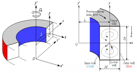
A 2D curved rectangular duct is considered for the present study. The rotating CRD is developed with a curvature ratio 0.001. Figure 1 illustrates the cross-sectional view and the coordinate system of the computational domain with the necessary notations. The x’ and y’ axes are considered to be in the horizontal and vertical directions, respectively and z’ along the center-line of the channel. The system rotates at a fixed angular motion ΩT around y’ axis. The outer wall of the domain is heated, and the inner wall is kept in normal room temperature. The remaining walls are well insulated to prevent any heat loss.
Figure 1. Coordinate system
Considering the flow as invariant in the z’ direction, which is driven by a specific pressure drop G along the center-line of the channel. The basic governing equations for the fluid flow and HT ([34]), are taken as:
Continuity equation:
$\frac{\partial u'}{\partial r'}+\frac{\partial v'}{\partial y'}+\frac{u'}{r'}=0$, (1)
Energy equation:
$\frac{\partial T^{\prime}}{\partial t^{\prime}}+u^{\prime} \frac{\partial T^{\prime}}{\partial r^{\prime}}+v^{\prime} \frac{\partial T^{\prime}}{\partial y^{\prime}}=\kappa\left[\frac{\partial^{2} T^{\prime}}{\partial r^{\prime 2}}+\frac{1}{r^{\prime}} \frac{\partial T^{\prime}}{\partial r^{\prime}}+\frac{\partial^{2} T^{\prime}}{\partial y^{\prime 2}}\right],$ (2)
Monetum equation:
$\begin{align} & \frac{\partial {u}'}{\partial {t}'}+{u}'\frac{\partial {u}'}{\partial {r}'}+{v}'\frac{\partial {u}'}{\partial {y}'}-\frac{{{{{w}'}}^{2}}}{{{r}'}}=-\frac{1}{\rho }\frac{\partial {P}'}{\partial {r}'} \\ & +\upsilon \left[ \frac{{{\partial }^{2}}{u}'}{\partial {{{{r}'}}^{2}}}+\frac{{{\partial }^{2}}{u}'}{\partial {{{{y}'}}^{2}}}+\frac{1}{{{r}'}}\frac{\partial {u}'}{\partial {r}'}-\frac{{{u}'}}{{{{{r}'}}^{2}}} \right] \\\end{align}$ (3)
$\begin{align} & \frac{\partial {v}'}{\partial {t}'}+{u}'\frac{\partial {v}'}{\partial {r}'}+{v}'\frac{\partial {v}'}{\partial {y}'}=-\frac{1}{\rho }\frac{\partial {P}'}{\partial {y}'}+\upsilon \left[ \frac{{{\partial }^{2}}{v}'}{\partial {{{{r}'}}^{2}}}+\frac{1}{{{r}'}}\frac{\partial {v}'}{\partial {r}'} \right. \\ & \left. +\frac{{{\partial }^{2}}{v}'}{\partial {{{{y}'}}^{2}}} \right]+g\beta {T}', \\\end{align}$ (4)
$\begin{align} & \frac{\partial {w}'}{\partial {t}'}+{u}'\frac{\partial {w}'}{\partial {r}'}+{v}'\frac{\partial {w}'}{\partial {y}'}+\frac{{u}'{w}'}{{{r}'}}=-\frac{1}{\rho }\frac{1}{{{r}'}}\frac{\partial {P}'}{\partial {z}'} \\ & +\upsilon \left[ \frac{{{\partial }^{2}}{w}'}{\partial {{{{r}'}}^{2}}}+\frac{{{\partial }^{2}}{w}'}{\partial {{{{y}'}}^{2}}}+\frac{1}{{{r}'}}\frac{\partial {w}'}{\partial {r}'}-\frac{{{w}'}}{{{{{r}'}}^{2}}} \right], \\\end{align}$ (5)
where, $r^{\prime}=L+\delta x^{\prime}$, and u’, v’ and w’ are the dimensional velocities along the x’, y’ and z’ directions respectively. The wall velocity is considered as zero. P’, T’ and t’ are the dimensional pressure, temperature, and time, respectively. In Eqns. (1) to (5), ρ, μ, β, κ and g are the density, kinematic viscosity, coefficient of thermal expansion, coefficient of thermal diffusivity and gravitational acceleration, respectively. A proper transformation was applied to make variables dimensionless which is not shown here for the brevity.
Since the flow is uniform along axial direction, the stream function Ψ is introduced in the horizontal and vertical direction respectively as:
$\left.\begin{array}{l}
u=\frac{1}{r} \frac{\partial \psi}{\partial y}=\frac{1}{1+\delta x} \frac{\partial \psi}{\partial y} \\
v=\frac{1}{r} \frac{\partial \psi}{\partial x}=-\frac{1}{1+\delta x} \frac{\partial \psi}{\partial x}
\end{array}\right\}$ (6)
So, the transformed basic equations for the Navier-Stokes equations and energy equation are expressed as:
$\begin{align} & (1+\delta x)\frac{\partial w}{\partial t}=Dn-\frac{1}{2}\frac{\partial (w,\psi )}{\partial (x,y)}-\frac{{{\delta }^{2}}w}{1+\delta x}+(1+\delta x){{\Delta }_{2}}w \\ & -\frac{1}{2}\frac{\delta }{(1+\delta x)}\frac{\partial \psi }{\partial y}w+\delta \frac{\partial w}{\partial x}-\delta Tr\frac{\partial \psi }{\partial y} \\\end{align}$ (7)
$\begin{align} & \left( {{\Delta }_{2}}-\frac{\delta }{1+\delta x}\frac{\partial }{\partial x} \right)\frac{\partial \psi }{\partial t}=-\frac{1}{2}\frac{1}{(1+\delta x)}\frac{\partial ({{\Delta }_{2}}\psi ,\psi )}{\partial (x,y)}+\Delta _{2}^{2}\psi \\ & +\frac{1}{2}\frac{\delta }{{{\left( 1+\delta x \right)}^{2}}}\times \left[ \frac{\partial \psi }{\partial y}\left( 2{{\Delta }_{2}}\psi -\frac{3\delta }{1+\delta x}\frac{\partial \psi }{\partial x}+\frac{{{\partial }^{2}}\psi }{\partial {{x}^{2}}} \right) \right. \\ & \left. -\frac{\partial \psi }{\partial x}\frac{{{\partial }^{2}}\psi }{\partial x\partial y} \right]+\frac{\delta }{{{\left( 1+\delta x \right)}^{2}}}\times \left[ 3\delta \frac{{{\delta }^{2}}\psi }{\partial {{x}^{2}}}-\frac{3{{\delta }^{2}}}{1+\delta x}\frac{\partial \psi }{\partial x} \right] \\ & -\frac{2\delta }{1+\delta x}\frac{\partial }{\partial x}{{\Delta }_{2}}\psi +\frac{1}{2}w\frac{\partial w}{\partial y}-Gr(1+\delta x)\frac{\partial T}{\partial x}-\frac{1}{2}Tr\frac{\partial \psi }{\partial y}, \\\end{align}$ (8)
$\frac{\partial T}{\partial t}=\frac{1}{\Pr }\left( {{\Delta }_{2}}T+\frac{\delta }{1+\delta x}\frac{\partial T}{\partial x} \right)-\frac{1}{(1+\delta x)}\frac{\partial (T,\psi )}{\partial (x,y)}$ (9)
The parameters Dn, Tr, Gr, and Pr, used in Eqns. (7) to (9) are calculated from following expression
$Dn=\frac{G{{d}^{3}}}{\mu \upsilon }\sqrt{\frac{2d}{L}},Gr=\frac{\beta g\Delta T\,{{d}^{3}}}{{{\upsilon }^{2}}},Tr=\frac{2\sqrt{2\delta }{{\Omega }_{T}}{{d}^{3}}}{\upsilon \delta },\operatorname{P}r=\frac{\upsilon }{\kappa }$
The applied boundary conditions for ω and Ψ are taken as:
$\begin{align} & w(\pm 1,y)=w(x,\pm 1)=\psi (\pm 1,y)=\psi (x,\pm 1) \\ & =\frac{\partial \psi }{\partial x}(\pm 1,y)=\frac{\partial \psi }{\partial y}(x,\pm 1)=0 \\\end{align}$ (10)
and the temperature T is treated as constant on the walls as
$T\left( 1,y \right)=1,\text{ }T\left( -1,y \right)=-1,\text{ }T\left( \pm x,1 \right)=x$ (11)
There is class of solutions which satisfy the following symmetry condition with respect to the horizontal plane y = 0:
$\left. \begin{matrix} w\left( x,y,t \right)\Rightarrow w\left( x,-y,t \right),\text{ }\!\!~\!\!\text{ } \\ \psi \left( x,y,t \right)\Rightarrow -\psi \left( x,-y,t \right), \\ T\left( x,y,t \right)\Rightarrow -T\left( x,-y,t \right) \\\end{matrix} \right\}$ (12)
The solution which satisfies condition (12) is called a symmetric solution otherwise it is an asymmetric solution. In the present study, Tr varies from -1000 to 1500 while Dn, Gr, Pr and curvature (δ) are fixed as Dn = 100, Gr = 500, Pr = 7.0 (water) and δ=0.001.
To solve the Eqns. (7) to (9) numerically, the spectral scheme is employed. According to the principle of this scheme, variables are expressed in a series of functions known as Chebyshev polynomials (detail calculations can be found in [19] and [24]).
The resistance coefficient (λ) is considered to investigate the representative quantity of the flow-state. It is defined as:
$\frac{{{P}_{1}}^{*}-{{P}_{2}}^{*}}{\Delta {{z}^{*}}}=\frac{\lambda }{{{d}_{h}}^{*}}\frac{1}{2}\rho {{\langle {{w}^{*}}\rangle }^{2}}$ (13)
where, < > are the mean over the cross-section and the hydraulic diameter is $d_{h}^{*} \cdot\langle w *\rangle$ is the axial velocity.
$\langle {{w}^{*}}\rangle =\frac{\nu }{4\sqrt{2\delta }d}\int_{-1}^{1}{dx}\int_{-1}^{1}{w(x,y,t)}dy$ (14)
Since $\frac{\left(P_{2}^{*}-P_{1}^{*}\right)}{\Delta z^{*}}=G, \lambda$ is related to the mean non-dimensional axial velocity <w> as:
$\lambda =\frac{16\sqrt{2\delta }Dn}{3{{\left\langle w \right\rangle }^{2}}}$ (15)
where, $\langle w\rangle =\frac{d\sqrt{2\delta }\langle {{w}^{*}}\rangle }{\nu }$.
The numerical accuracy of the present study is performed. For the curved rectangular duct of aspect ratio 2, Yanase et al. [15, 24] showed that N = 2M gives sufficient accuracy of the solution, where M and N represent the truncation numbers (grid points) in the x- and y-directions respectively. Therefore, to test the accuracy of the present numerical solution we have chosen 5 test cases of M and N from low to high values such as 16×32, 18×36, 20×40, 22×44 and 24×48 as presented in Table 1, where it is showed that a small change in grid points affects the numerical accuracy. In Table 1, λ is the resistance coefficient defined in Eq. (13) and w(0,0) is the axial velocity of the steady solution at (x, y) = (0,0). As seen in Table 1, sufficient accuracy is attained if $M \geq 20$ and $N \geq 40$. In the present study, however, to minimize the computational cost, we have used M = 20 and N = 40 to obtain numerical data, which gives sufficient accuracy.
Table 1. The values of resistance coefficient (λ) and axial velocity w(0, 0) for various of M and N at Dn=100, Tr = 1000, Gr = 500 and δ=0.001
|
M |
N |
λ |
w(0, 0) |
|
16 |
32 |
0.10818253577 |
737.7593943610 |
|
18 |
36 |
0.10818339665 |
737.9873011866 |
|
20 |
40 |
0.10818327852 |
738.1101355561 |
|
22 |
44 |
0.10818315944 |
738.1329848552 |
|
24 |
48 |
0.10818303917 |
738.1505493243 |
4.1 Case I: Positive rotation
4.1.1 Steady solutions and flow patterns
The steady solution and corresponding flow patterns are investigated for the positive rotation of the CD. The path continuation technique is employed with different assumptions, and the numerical result reports two-branches asymmetric solution (Figure 2(a)). The overall investigation is performed for a wide range of the rotational parameter $0<T r \leq 1500$. The two branches are defined as first and second steady solution branch, respectively.
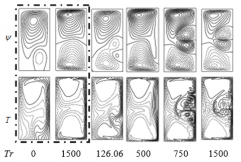
The velocity contour and isotherms are investigated for different Tr. Figure 2(b) represents the secondary flow velocity contour and temperature distribution at different selected Tr on the steady solution branch. The overall velocity streamlines report that the number of Dean vortices increases with the rotational value. For the first branch, a two-vortex velocity contour is observed, and the Tr shows no flow instability. However, a complex flow behavior is observed for the second branch. The numerical results show two- to four-vortex solutions for different Tr. The second branch started at Tr = 126, and a transitional four-vortex solution is observed. A two-vortex solution is found at Tr = 500. The overall secondary flow pattern shows a highly asymmetric flow behavior at different Tr on the second branch.
The first steady solution, shown by a solid red line in Figure 2(a), starts at point a (Tr = 0) and ends at the point b at Tr = 1500. The first steady branching solution shows an increasing trend of resistance coefficient and the resistance coefficient increases with the Tr. The second branch steady solution is investigated for the CD. The branching pattern of the second steady solution, shown in Figure 2(a) with solid blue line, started at point c (Tr = 1500), and the Tr started decreasing. At point d (Tr = 125.065), the solution branch makes turns and started increasing again up to point e. The relationship of the calculated resistance coefficient and Tr is found proportional for the second steady branch.
As seen in the secondary flow patterns, the secondary flow consists of two- or more-vortex solutions which are asymmetric with respect to the horizontal plane y = 0. The reason is that heating the outer wall causes deformation of the secondary flow and yields asymmetry of the flow. With the heating and cooling the sidewalls changes of fluid density that induce thermal convection in the fluid; the resulting flow behavior in the cross section is, therefore, determined by the combined action of the radial flow caused by the centrifugal body force and the convection caused by the buoyancy force due to temperature difference between the walls. This asymmetry of the flow is well discussed in the papers by Yanase et al. [14] and Mondal et al. [25].
4.1.2 Analysis of transient solution
The transient solution of the fluid flow has been performed for a wide range of Tr. The numerical results illustrate the non-linear behavior of the transient solutions. The overall investigations are performed for a constant pressure gradient value (Dn = 100) and the constant heat transfer parameter (Gr = 500). The numerical approach investigates the effects of rotating CD on fluid flow and HT.
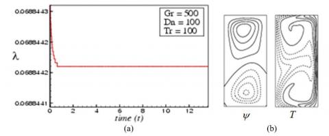
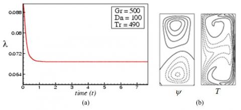
The transient flow analysis through the rotating duct depicts a steady solution for low rotational values ($0 \leq \operatorname{Tr} \leq 490$) The transient solution against resistance coefficient (Figures 3 and 4) shows a steady flow pattern for low Tr. The corresponding secondary flow contour shows a two-vortex (Figure 3(b)) steady solution pattern.
(a)
(b)
Figure 2. (a) Steady solutions (b) Streamlines (top) and isotherms (bottom) for various Tr (The dotted rectangular box represents the solution for the first branch)
Figure 3. Unsteady solution for Tr = 100. (a) Transient solution of λ, (b) velcocity contour (left) and isotherm (right) at t = 10
Figure 4. Transient solution for Tr = 490. (a) Transient solution of λ, (b) velcocity contour (left) and isotherm (right) at t = 6.0
Figure 5. Transient solution for Tr = 495. (a) λ as a function of time, (b) velcocity contour (top) and isotherm (bottom) for $11.0 \leq t \leq 11.25$
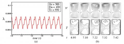
Figure 6. Transient solution for Tr = 550. (a) λ as a function of time, (b) velcocity contour and isotherm for $6.95 \leq t \leq 7.42$
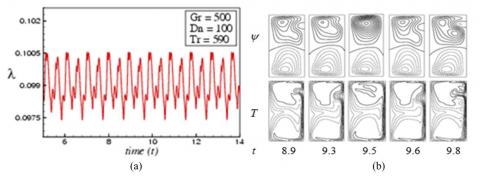
Figure 7. Transient solution for Tr = 590. (a) λ as a function of time, (b) velcocity contour and isotherm for $8.9 \leq t \leq 9.8$
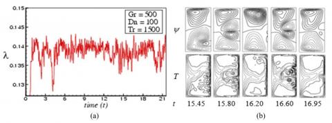
Figure 8. Transient solution for Tr = 1500. (a) λ as a function of time, (b) velcocity contour and isotherm for $15.45 \leq t \leq 16.95$
Figure 9. The phase spaces in the λ - γ plane for; (a) Tr = 495, (b) Tr = 550, (c) Tr = 1500
The numerical study investigated the transitional flow behavior for a rotating domain, and the steady-periodic solution is observed at Tr = 495. At Tr = 495, the transition starts, and the velocity contour reports a two-vortex solution (Figure 5). A comprehensive analysis has been performed for the flow characterization, and the numerical study shows steady-periodic solution for $495 \leq T r \leq 530$. It is observed that the flow transition from steady-state solution to periodic solution oscillation holds between Tr = 490 and Tr = 495. If Tr is enhanced again, for instance Tr = 550, the periodic flow goes into the multi-periodic flow, as shown in Figure 6(a). The transition of flow configuration has been discovered as periodic oscillation to multi-periodic flow between Tr = 530 and Tr = 550. The velocity contours and temperature contours are shown in Figure 6(b) for Tr = 550 and an asymmetric two-vortex solution is observed. The fluid flow pattern changes with the increase of the rotational value, and a multi-periodic flow pattern is observed at Tr = 590. Figure 7 shows the transient solutions and the corresponding velocity and temperature contours. The velocity contour shows two- to three-vortex solutions. The temperature contour shows asymmetric temperature distribution at different selected times. The time-dependent flow at Tr = 1500 (Figure 8(a)) oscillates irregularly in a highly non-linear manner that means the flow is a strong chaos at Tr = 1500, Figure 8(b) reports up to four-vortex solution at Tr = 1500, and the corresponding temperature distribution is found highly asymmetric. The higher rotational value influences the fluid flow and heat transfer through the duct.
4.1.3 Phase spaces for positive rotation
In order to well justify the transition from one state to another for various time-dependent solutions, phase spaces are sketched for the transient solutions in the λ-γ plane, where $\gamma=\iint \psi d x d y$. Figure 9(a) shows phase plots for Tr = 495, which spectacles that the fluid particles form a unique orbit, which proves that the fluid travels in a periodic path for Tr = 495. We also obtained periodic oscillation by time evolution calculation.
By conducting the time history analysis, we found a multi-periodic solution for Tr = 550, which is also aligned with the phase plotting, as demonstrated in Figure 9(b) for Tr = 550. By the time evolution calculation, we could not well justify the characteristics of the flow for Tr = 590; however, their phase space exhibits that the fluid flow is a transition to chaos rather than multi-periodic. Finally, we draw the phase spaces for Tr = 1500 in Figure 9(c), which reports that the flow pattern is highly chaotic.
4.2 Case II: Negative rotation
4.2.1 Analysis of transient solution
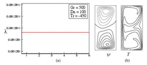
The fluid flow characterization through a CD is performed for negative rotation. A wide range of negative rotational parameter (Tr) values is used to investigate the transient solution. The numerical results show a steady flow behavior for all the values of Tr in $-500 \leq T r<0$. The velocity contour and temperature distribution contour (Figure 10) are performed for Tr = - 450, and an asymmetric two-vortex solution is observed.
A comprehensive fluid flow characterization is performed for negative rotation, and the overall numerical calculations report that the flow becomes steady to periodic at Tr = -490. Figure 11 shows the time-dependent solution for Tr = -500 which shows a fully periodic behavior. The corresponding velocity contour at different selected time shows a symmetric two-vortex solution for Tr = -500. The temperature contour also shows a symmetric distribution pattern for all selected points. The fluid flow pattern becomes fully periodic to multi-periodic state at higher negative Tr. As seen in Figure 11, the time-dependent flow shows almost same behavior after a fixed time-period. On the contrary, the multi-periodic flow completes more than one cycle before repeating the same behavior (Mondal et al. [19]; Islam et al. [5]). In this study, as the rotation is increased the periodic flow turns into multi-periodic flow. The periodic flow in the present study corresponds to a travelling-wave solution in real flows. There are evidences to describe this flow behavior. Mees et al. [35, 36] observed traveling wave solutions in the study of curved duct flows. They observed the change of secondary flow pattern far downstream using a spiral duct, where Dn increases in the downstream due to an increase of the curvature. In fact, the periodic oscillation observed in the cross-section of their duct, was a traveling-wave advancing in the downstream direction that was justified in a 3D study of the curved square duct flow by Yanase et al. [37]. Therefore, our numerical results can accurately predict the existence of 3D traveling wave solutions by showing an appearance of periodic or multi-periodic oscillation in the present study.
Figure 10. Transient solution for Tr = -450. (a) λ as a function of time, (b) velocity contour (left) and isotherm (right) at t = 6
Figure 11. Transient solution for Tr = -500. (a) λ as a function of time, (b) velocity contour and isotherm for $45.10 \leq t \leq 45.33$
Figure 12. Transient solution for Tr = -590. (a) λ as a function of time, (a) velocity contour and isotherm for $7.11 \leq t \leq 7.80$
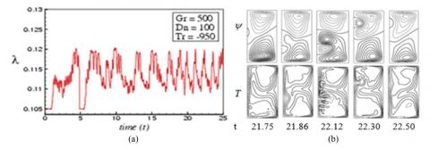
Figure 13. Transient solution for Tr = -950. (a) λ as a function of time, (b) velocity contour and isotherm for $21.75 \leq t \leq 22.50$
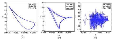
Figure 14. Phase spaces in the λ - γ plane for; (a) Tr = -500, (b) Tr = -590, (c) Tr = -950
Figure 12 shows the resistance coefficient variation against time, and the resistance coefficient values fluctuate with the time. The velocity contour reports an asymmetric two-vortex solution for Tr = -590. The temperature contour also shows asymmetric behavior at different selected points. The numerical study observed muti-periodic solution for any value of Tr in the range $-660 \leq T r \leq-590$ . In order to find the chaotic region, we further increased Tr in the negative direction, and a highly chaotic solution is observed for all values in $-1000 \leq T r \leq-675$. Figure 13(a) shows the transient result for Tr = -950 and corresponding secondary flow patterns are displsyed in Figure 13(b).
The numerical calculation illustrates that the transition from a multi-periodic solution to chaotic solution occurs between Tr = -660 and Tr = -675. The chaotic oscillation at Tr = -675 is called transitional chaos, while that for Tr = -950 strong chaos (Mondal et al. [34]). The secondary flow pattern reports a highly asymmetric chaotic oscillation, and up to four-vortex solution is observed. The centrifugal, Coriolis, and buoyancy forces influence the overall flow pattern and Dean vortices.
The present study shows that for small Dean number (Dn = 100), the unsteady flow is steady-state for small Tr. However, as Tr is increased, either in the positive or in the negative direction, the Coriolis force becomes strong which dominates the centrifugal force and consequently the steady-state flow turns into chaos via periodic and multi-periodic oscillations like “Steady-state → periodic →multi-periodic→ chaotic” if Tr is increased. The reason is that due to small Dn, the Coriolis force dominates the centrifugal force so that the flow oscillates irregularly with large windows of quasi-periodic oscillations. The opposite scenario is observed in the paper by Islam et al. [5] where they investigated flow instability for large Dean numbers (Dn = 1000 & 1500) with positive and negative rotation of the duct. They showed that the unsteady flow becomes chaotic for small Tr (Tr = 0); however, as Tr is increased in the positive or in the negative direction, the flow becomes steady-state via multi-periodic or periodic oscillation in the scenario “Chaotic → multi-periodic → periodic → steady-state” if Tr is increased.
4.2.2 Phase spaces for negative rotation
In order to justify the transitional behavior of the fluid flow, we explicitly draw the orbits of the phase space in the λ-γ plane. Figure 14(a) describes the phase diagram of the transient solutions for Tr = -500, where the flow forms a single orbit that clearly concludes the periodic solution at Tr = -500. Figure 14(b) illustrates multiple orbits at Tr = -590, which indicate the fluid flow pattern for the specified rotational value is multi-periodic. The λ-γ plane for higher Tr (Tr = -950) reports very irregular orbits in the phase space, which indicates the fluid flow pattern is strongly chaotic. This type of flow oscillation is termed as strong chaos (Mondal et al. [19] and Yanase et al. [24]).
In this study, it is observed that if Tr is increased, an alternating occurrence of the oscillating and chaotic states is perceived. The occurrence of the chaotic state, as justified by the phase spaces in the present study, suggest that the Ruelle-Takens [38] mechanism plausibly works for the occurrence of chaos in the present system. The transition to chaos of the periodic oscillation may correspond to the destabilization of the traveling waves in the curved duct flows like that of Tollmien-Schlichting waves in a boundary layer. It is, therefore, suggested that occurrence of the chaotic state in the present study is related with destabilization of the steady solutions, which reminds us the case of Lorenz chaos [39].
4.3 Heat Transfer
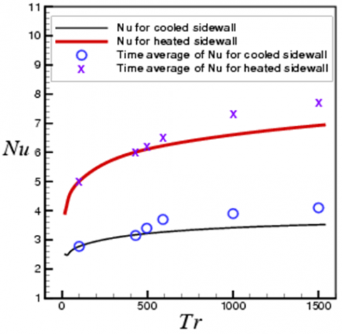
The convective HT from the hot wall of the computational domain to the working fluid is investigated for different Tr. The Nusselt number (Nu) for the hot and cool walls are calculated for different rotational values. For unsteady flow fields, time-average Nu is calculated for both walls. Figure 15 shows the calculated Nu for the first steady-state solution branch. For small curvature, the overall Nu at the heated wall and the cooled wall is found proportional to the Tr. The calculated Nu at the hot wall is 2.2 times higher than the cool wall at Tr = 1500 for both steady and time-averaged cases (Figure 15). The numerical calculation reports that the calculated Nu is for the steady and time-averaged approach is different for both walls. However, for lower Tr (Tr ≤ 500), the Nu is found almost similar for both steady and time-averaged cases. The overall investigation shows higher Nu at the heated wall for higher Tr, which eventually indicate the higher HT from the hot wall to the fluid. The Nu variation for the time-averaged and steady case indicate that the transitional flow pattern affects the HT.
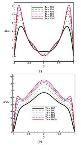
For a better understanding of the convective HT from the hot wall to the fluid, a comprehensive temperature profile is calculated for both walls. Figures 16(a) and 16(b) show the corresponding temperature drop with different Tr for the cool and hot wall, respectively. The temperature profile for the cooled wall for different Tr reports higher temperature drop at the centre of the wall (y = 0). The centrifugal force and corresponding advective heat generation to the outward direction influence the HT at the centre of the wall. On the contrary, the temperature profile shows an increasing trend near the wall irrespective to the Tr. The secondary flow in the inward direction and corresponding advective HT influences the temperature drop near the wall. For the heated wall, the temperature profile for different Tr shows a similar increasing trend and the temperature gradient is found maximum at the centre of the domain.
Figure 15. Variation of Nu with Tr for the first steady solution branch
Figure 16. Temperature gradients at the (a) cool wall, (b) hot wall
4.4 Validation of the numerical result
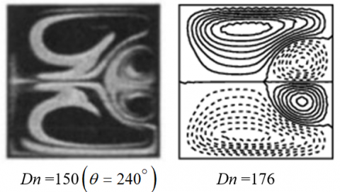
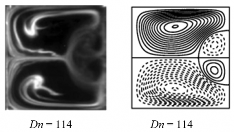
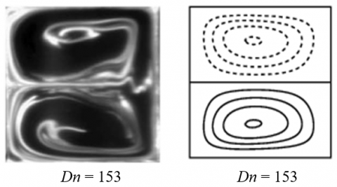
The numerical findings of the present study are validated with some available experimental measurements. Figure 17 shows a comparative study of the contour of secondary flow structure between the experimental data obtained by Mees et al. [40] and the numerical result by the authors for the stationary curved square duct flow. The experimental duct in their study was formed for incompressible Newtonian fluid that were observed at $40^{\circ}$ inlet. Figure 18 shows the velocity contour for positive rotation of the duct. Yamamoto et al. [20] adopted the visualization technique to explore the experimental outcome considering the rotation of the three walls except the outer-wall. The experimental measurements of Yamamoto et al. [20] for small curvature show a good agreement with the findings of the present study. At Tr = 150 and Dn = 114, the experimental and the numerical study shows a similar four-vortex solution. The rotational speed and curvature are the same for both studies. For negative rotation at Tr = -150 and Dn = 153 (Figure 19) both measurement shows similar two-vortex solutions, which clearly indicates that the present numerical approach is accurate enough to predict the transitional behavior of the fluid flow for small curvature-shaped duct.
A relative comparison has been performed for a curved rectangular duct with curvature d = 0.032, and the study did not consider any rotation. Figure 20 presents a relative comparison of the numerical findings with the experimental measurement by Chandratilleke [23]. Both the experimental and numerical results show a similar secondary flow pattern. The numerical study shows a good match with the different published experimental measurement, which proves the accuracy of the present numerical study. Note that, till now no experimental data is available in literature for rotating curved rectangular duct flow.
Figure 17. Secondary flow comparison for stationary curved square duct (CSD) flow. (Left: Experimental data [40] and right: numerical by the authors
Figure 18. Secondary flow comparison for rotating curved duct (CD) flow at Tr = 150. (Left: Experimental [20] and right: numerical by the authors)
Figure 19. Secondary flow comparison for rotating CD flow at Tr = -150. (Left: Experimental [20] and right: numerical by the authors)
Figure 20. Secondary flow comparison for stationary CD of aspect ratio 2. (Left: Experimental [23] and right: numerical by the authors)
The present spectral-based approach investigates the fluid flow characterization and HT through a rotating CD with small curvature. The rotational parameter effects on fluid flow and HT are investigated for constant pressure gradient and constant Gr. The numerical findings are validated with the available experimental data. The following conclusions are drawn from the present numerical study:
The present study comprehensively performs the fluid flow transition and HT through a rotating CD with small curvature. The findings of the present study will increase the understanding of the fluid flow and HT through a small-curvature duct. This study, along with more case studies, will improve the understanding of the field.
Rabindra Nath Mondal, one of the authors, would gratefully acknowledge the financial support from the Bangladesh Ministry of Education (MoEdu) for advanced research in Science and Technology (No. 37.20.0000.004.033.005.2014-1309/1(42)) to conduct this research work.
[1] Dean, W.R. (1927). Note on the motion of fluid in a curved pipe. Phil. Mag., 4(20): 208-223. https://doi.org/10.1080/14786440708564324
[2] Berger, S.A., Talbot, L., Yao, L.S. (1983). Flow in Curved Pipes. Annual. Rev. Fluid. Mech, 35: 461-512. http://dx.doi.org/10.1146/annurev.fl.15.010183.002333
[3] Nandakumar, K., Masliyah, J.H. (1986). Swirling Flow and Heat Transfer in Coiled and Twisted Pipes. Adv. Transport Process, 4: 49-112.
[4] Ito, H. (1987). Flow in Curved Pipe. JSME Int. J., 30: 543-552. https://doi.org/10.1299/jsme1987.30.543
[5] Islam, M.Z., Mondal, R.N., Rashidi, M.M. (2017). Dean-Taylor flow with convective heat transfer through a coiled duct. Computers and Fluids, 149: 41-55. https://doi.org/10.1016/j.compfluid.2017.03.001
[6] Islam M.Z., Rashid, M.H., Mondal, R.N. (2018). Efferct of Coriolis force on unsteady flow with convective Heat Transfer through a curves duct in case of negative rotation. AIP Conference Proceedings, 1980 (050019): 1-9. https://doi.org/10.1063/1.5044355
[7] Ghia K.N., Sokhey, J.S. (1977). Laminar incompressible viscous flow in Curved Ducts of rectangular cross-section. Trans. ASME I: Journal of Fluids Engineering, 99: 640-648. https://doi.org/10.1115/1.3448875
[8] Ishigaki, H. (1996). Laminar flow in rotating curved pipes. J. of Fluid Mechanics, 329: 373-388. https://doi.org/10.1017/S0022112096008956
[9] Selmi, M., Namdakumar, K., Finlay, W.H. (1994). A bifurcation study of viscous flow through a rotating Curved Duct. J. Fluid Mech., 262: 353-375. https://doi.org/10.1017/S0022112094000534
[10] Hasan, M.S., Mondal, R.N., Lorenzini, G. (2020). Physics of bifurcation of the flow and heat transfer through a curved duct with natural and forced convection. Chinese Journal of Physics, 67: 428-457. https://doi.org/10.1016/j.cjph.2020.07.004
[11] Hasan, M.S., Mondal, R.N., Lorenzini, G. (2020). Coriolis force effect in steady and unsteady flow characteristics with convective heat transfer through a curved square duct. Int. J. Mechanical Engineering, 5(1): 1-39. https://www.researchgate.net/publication/351956607
[12] Selmi, M., Namdakumar, K. (1999). Bifurcation study of the flow through rotating curved ducts. Physics of Fluids, 11: 2030-2043. https://doi.org/10.1063/1.870066
[13] Wang, L.Q., Cheng, K.C. (1996). Flow transitions and combined free and forced convective heat transfer in rotating curved channels: The case of positive rotation. Physics of Fluids, 8: 1553-1573. https://doi.org/10.1063/1.868930
[14] Yanase, S., Nishiyama, K. (1988). On the bifurcation of laminar flows through a curved rectangular tube. J. Phys. Soc. Japan, 57(11): 3790-3795. https://doi.org/10.1143/JPSJ.57.3790
[15] Yanase, S., Kaga, Y., Daikai, R. (2002). Laminar flow through a curved rectangular duct over a wide range of the aspect ratio. Fluid Dynamics Research, 31: 151-183. https://doi.org/10.1016/S0169-5983(02)00103-X
[16] Wang, L., Yang, T. (2005). Periodic oscillation in curved duct flows. Physical D: Nonlinear Phenomena, 200: 296-302. https://doi.org/10.1016/j.physd.2004.11.003
[17] Hasan, M.S., Islam, M.S., Badsha, M.F., Mondal, R.N., Lorenzini, G. (2020). Numerical investigation on the transition of fluid flow characteristics through a rotating curved duct. International Journal of Applied Mechanics and Engineering, 25(3): 45-63. https://doi.org/10.2478/ijame-2020-0034
[18] Hasan, M.S., Mondal, R.N., Lorenzini, G. (2021). Centrifugal-Coriolis instability through a rotating curved square duct with bottom wall heating and cooling from the ceiling. AIP Conference Proceedings, 2324(1): 040007. https://doi.org/10.1063/5.0037784
[19] Mondal, R.N., Kaga, Y., Hyakutake, T., Yanase, S. (2007). Bifurcation diagram for two-dimensional steady flow and unsteady solutions in a curved square duct. Fluid Dynamics Research, 39: 413-446. https://doi.org/10.1016/j.fluiddyn.2006.10.001
[20] Yamamoto, K., Wu, X.Y, Nozaki, K., Hayamizu, K. (2006). Visualization of Taylor-dean flow in a curved duct of square cross-section. J. Fluid dynamics research 38: 1-18. https://doi.org/10.1016/j.fluiddyn.2005.09.002
[21] Mondal, R.N., Islam, M.Z., Islam, M.S. (2013). Transient heat and fluid flow through a rotating curved rectangular duct: the case of positive and negative rotation. Procedia Engineering, 56: 179-186. https://doi.org/10.1016/j.proeng.2013.03.105
[22] Mondal, R.N., Ray, S.C., Yanase, S. (2014). Combined effects of centrifugal and Coriolis instability of the flow through a rotating curved duct with rectangular cross section. Open Journal of Fluid Dynamics, 4: 1-14. https://doi.org/10.4236/ojfd.2014.41001
[23] Chandratilleke, T.T. (2001). Secondary flow characteristics and convective heat transfer in a curved rectangular duct with external heating. 5th World Conference on Experimental Heat Transfer, Fluid Mechanics and Thermodynamics [ExHFT-5], Thessaloniki, Greece.
[24] Yanase, S., Mondal, R.N., Kaga, Y. (2005). Numerical study of non-isothermal flow with convective heat transfer in a curved rectangular duct. Int. J. Thermal Sciences, 44: 1047-1060. https://doi.org/10.1016/j.ijthermalsci.2005.03.013
[25] Mondal, R.N., Kaga, Y., Hyakutake, T., Yanase, S. (2006). Effects of curvature and convective Heat Transfer in curved square duct flows. Trans. ASME, Journal of Fluids Engineering, 1289(9): 1013-1023. https://doi.org/10.1115/1.2236131
[26] Norouzi, M., Kayhani, M.H., Nobari, M.R.H., Demneh, M.K. (2009). Convective heat transfer of viscoelastic flow in a curved duct. World Academy of Science. Engineering and Technology, 32: 327-333. https://publications.waset.org/13409
[27] Chandratilleke, T.T., Nadim, N., Narayanaswamy, R. (2012). Vortex structure-based analysis of laminar flow behavior and thermal characteristics in curved ducts. Int. J. Thermal Sciences, 59: 75-86. https://doi.org/10.1016/j.ijthermalsci.2012.04.014
[28] Norouzi, M., Biglari, N. (2013). An analytical solution for dean flow in curved ducts with rectangular cross section. Physics of Fluids, 25: 1-15. https://doi.org/10.1063/1.4803556
[29] Wu, X.Y., Lai, S.D., Yamamoto, K., Yanase, S. (2013). Numerical analysis of the flow in a curved duct. Advanced Materials Research, 706-708: 1450-1453. https://doi.org/10.4028/www.scientific.net/AMR.706-708.1450
[30] Razavi, R., Soltanipour, S.E., Choupani, P. (2015). Second law analysis of laminar forced convection in a rotating curved duct. Thermal Science, 19(1): 95-107. https://doi.org/10.2298/TSCI120606034R
[31] Hasan, M.S., Mondal, R.N., Yanase, S. (2021). Numerical prediction of unsteady fluid flow and heat transfer through a stationary curved square duct. AIP Conference Proceedings, 2324(1): 050020. https://doi.org/10.1063/5.0037783
[32] Hasan, M.S., Dolon, S.N., Chakraborty, H.S., Mondal, R.N., Lorenzini, G. (2021). Numerical investigation on flow transition through a curved square duct with negative rotation. Journal of Applied and Computational Mechanics, 7(3): 1435-1447. https://doi.org/10.22055/JACM.2020.33606.2253
[33] Chanda, R.K., Hasan, M.S, Alam, M.M., Mondal, R.N. (2021). Taylor-heat flux effect on fluid flow and heat transfer in a curved rectangular duct with rotation. Int. J. Appl. and Comp. Mathematics, 7: 146. https://doi.org/10.1007/s40819-021-00986-8
[34] Mondal, R.N., Islam, M.Z., Islam M.M., Yanase, S. (2015). Numerical study of unsteady heat and fluid flow through a curved rectangular duct of small aspect ratio. Thammasat International Journal of Science and Technology, 20(4): 1-20. Retrieved from https://ph02.tci-thaijo.org/index.php/SciTechAsia/article/view/44164.
[35] Mees, P.A.J., Nandakumar, K., Masliyah, J.H. (1996). Instability and transitions of flow in a curved square duct: the development of the two pairs of dean vortices. J. Fluid Mech., 314: 227-246. https://doi.org/10.1017/S0022112096000298
[36] Mees, P.A.J., Nandakumar, K., Masliyah, J.H. (1996). Steady spatial oscillations in a curved duct of square cross-section. Physics of Fluids, 8(12): 3264-3270. https://doi.org/10.1063/1.869108
[37] Yanase S., Watanabe T., Hyakutake T. (2008). Traveling-wave solutions of the flow in a curved-square duct. Physics of Fluids, 20: 124101. https://doi.org/10.1063/1.3029703
[38] Ruelle, D., Takens, F. (1971). On the nature of turbulence. Commun Math Phys., 20: 167-92. https://doi.org/10.1007/BF01646553
[39] Lorenz, E.N. (1963). Deterministic non-periodic flow. J. Atoms Sci., 20: 130-141. https://doi.org/10.1175/1520-0469(1963)020<0130: DNF>2.0.CO;2
[40] Mees P.A.J., Nandakumar K., Masliyah, J.H. (1996). Secondary instability of flow in a curved duct of square cross section. Journal of Fluid Mechanics, 323: 387-409. https://doi.org/10.1017/S0022112096000973