Md. Rafiqul Islam* | Sonia Nasrin
© 2021 IIETA. This article is published by IIETA and is licensed under the CC BY 4.0 license (http://creativecommons.org/licenses/by/4.0/).
OPEN ACCESS
This study presents the one-dimensional unsteady micropolar fluid flow set in a porous medium along with an inclined infinite Riga plate. This Riga plate is created an electric and magnetic field, where a transverse Lorentz force is generated that contributes a flow along with the plate. The explicit finite difference method is used to find the solution of the non-dimensional form of the governing equations and estimated results are analyzed in terms of Microrotation parameter, Suction parameter, thermal Grashof number, mass Grashof number, Permeability parameter, Hartmann number, Dufour number, Soret number, Schmidt number. Also, the effects of the pertinent parameters on the local and average shear stress, Nusselt number, and Sherwood number are reported numerically as well as graphically.
micropolar fluid, Riga plate, heat transfer, mass transfer, inclined angle
Micropolar fluids are randomly oriented micro-structured particles with their spin inertia and ceased in a viscous medium. Well known that for the huge erosion of micropolar fluids. conventional Newtonian fluids cannot clearly state the properties of the fluids with ceased particles which are presented the applications in the non-Newtonian fluids, polarities of idiosyncratic particulars, polymer fluids, animal blood and liquid crystals. Eringen [1] first proposed the general theory which illustrates certain microscopic effects arising from the microstructure and micro motions of flow is micropolar fluids which exhibits the micro-rotational effects and micro-rotational inertia and so that clench body couples and couple stress. The Navier-Stokes theory is unable to express the phenomena of circulation at micro and nanoscales. On the other hand, MFD can express the physical phenomena at micro and nano scales which are freely rotating. Gorla [2] has been analyzed the mixed convection to a micropolar fluid from a semi-infinite vertical plate with the rate of heat transfer and showed the comparison of Newtonian and micropolar fluids. The comparison gives the drag transfer and reduced heat flux of micropolar fluid. Hudimoto and Tokuoka [3] have devised the two-dimensional parallel shear flow of linear micropolar fluids. They analyzed and compared micropolar fluids with the colloidal suspensions. The obtained result is satisfied with Einstein's formula for the lyophobic sol otherwise viscosity-concentration relations are reduced for lyophilic sol. Nadeem et al. [4] explored the micropolar fluid flow over an oscillating plate adjacent in porous media set in vertically so that the free convections are created for the differences in temperature and concentration. They are interested because the flow through a porous medium has significant uses in electronic and welding manufacturing processes, nuclear waste storage processes, groundwater flows, polluted soil, food procedure, oil recovery, thermal engineering, agricultural water distribution and the chemical industry. Hossain and Chowdhury [5] presented a united micropolar fluid flow over an isothermal heated plate with variable spin gradient viscosity. Mansour et al. [6] studied the MHD micropolar fluid flow on a circular cylinder with heat and mass transfer. The comparison of the micropolar fluid behavior with Newtonian fluids shows a retrenchment in drag while heat transfer is also reduced. Mohamed and Zaki [7] designed the electric effect on a micropolar viscoelastic rotating fluid with convective instability. Reddy et al. [8] have introduced the natural convection in a rectangular porous medium of micropolar fluid flow.
Riga plate is an electromagnetic actuator, which is made by the combination of a span-wise aligned array of alternating electrodes and permanent magnets. This plate is created an electric and magnetic field, where a transverse Lorentz force is generated that contributes a flow along with the plate. Micropolar fluid flows along porous Riga plate focuses a famous research area that has formidable applications in industrial and engineering processes, dust or fumes in a gas, in biomechanics, purifying the groundwater pollution and food processing. Riga plate was first introduced by Gailitis and Leilausis [9] and they were generated a wall paralleled Lorentz force to control the fluid flow. Further, in contrast to the Grinberg-term was introduced with a most important feature that the boundary layer of momentum equation is fully separate from the flow and exponentially decreases in the direction of the normal to the plate. After that when the Lorentz force was detected over a Riga plate, and then the researchers regained interest in the Gailitis-Lielausis actuator. Anjum et al. [10] reported the clench body couples velocity and thermal slip effects are conjoined to express the flow of viscous fluid instigating by a non-linear stretched Riga plate. They have found the stagnation point of a viscous fluid due to a non-linear stretched Riga plate where the heat transfer characteristics are executed by solar thermal radiation. Thereafter many researchers suggested the new idea of the effect on the Riga plate with micropolar fluids or nanofluids. Pantokratoras and Magyari [11] are designed the electro-magneto hydrodynamic free convection flow of a weakly conducting fluid along with a Riga plate, but Pantokratoras [12] improved that the Riga-plate is either moved with a constant velocity or the Riga-plate is situated in a Blasius flow. Ahmad [13] studied the effect of the Powell - Eyring and Reiner-Phillipoff fluid flow on Riga plate. Yucel [14] explained the associated free convection flow in a micropolar fluid through a Riga plate. The theme is reported by Wahidunnisa et al. [15] is that the study of a mixed convective nanofluid flow along a heated Riga-plate with viscous dissipation and heat source. Iqbal et al. have found the stagnation point flow of the melting heat, thermal radiation and viscous dissipation effects on Riga plate using erratic thickness and considered the Cassion fluid stagnation point flow along with a Riga plate [16, 17]. Ayub et al. [18] analyzed the effect of EMHD nano-fluid flow along with a Riga plate. Harutha and Devasena [19] prescribed the micropolar fluid flow on a vertical surface through a porous medium towards a stagnation point. Shamshuddin and Thumma [20] introduced the chemically reacting micropolar fluid flow with heat and mass transfer along a porous medium in an inclined plate is set with the heat source. Abel and Veena [21] examined the heat transfer and visco elastic fluid flow along with a stretching sheet through a porous medium. Rajput and Gupt [22] have given the idea about Dafour effect on unsteady free convection MHD fluid flow through a porous media past an accelerated plate with variable temperature and mass diffusion in the presence of an inclined magnetic field. Angirasa and Peterson [23] have been investigated, in the presence of a porous medium the fluid with Darcy flow is saturated and temperature profiles are significantly smaller in the porous medium. Pattnaik et al. [24] have analyzed the heat and mass transfer of free convection flow along the exponentially accelerated inclined plate with an angle of inclination where magnetic field and porous medium obstruct the turbulent flow of the fluid. Daniel and Daniel [25] have found the fluid flow along a porous structure with heat transfer through an inclined channel in the presence of the pressure gradient. Hanvey et al. [26] investigated the heat and mass transfer of an incompressible fluid flow along two parallel plates with porous medium and inclined magnetic field. Recently Nadeem et al. [27] examined the steady heat transfer of a three dimensional micropolar fluid over an exponentially stretching surface on the Riga plate.
From the above-mentioned discussions of the authors, it has come to a new opinion that this research has not been discussed yet before. In this paper, the main target is to investigate the behavior of a micropolar fluid along with an inclined Riga plate with heat and mass transfer set in a porous medium. The significant results have been discussed briefly and shown graphically.
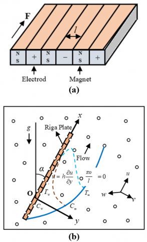
Consider an unsteady one-dimensional viscous incompressible electrically conducting micropolar fluid flow with mass transfer past along with a porous Riga plate inclined at an angle$\,\alpha $ with vertical direction, which is embedded in a saturated porous medium. The coordinate system has been taken in such a way that $\tilde{x}\text{-}$axis is along the direction of the Riga plate and $\tilde{y}$ - axis is normal to it. It is assumed that at $\tilde{t} \leq 0$ the velocity, microrotation, temperature and concentration of the fluid are respectively $\,\,\tilde{u}=0,\,$$\,\,\tilde{\Gamma }=0,\,$$\,\,\,\tilde{T}={{\tilde{T}}_{\infty }}\,$and$\tilde{C}={{\tilde{C}}_{\infty }}$. At time $\tilde{t}>0$, Riga plate moves with a velocity $\frac{\pi \upsilon }{l}$ in a porous medium. The temperature of the plate and the concentration are raised from ${{\tilde{T}}_{w}}$ to $\,{{\tilde{T}}_{\infty }}$ and ${{\tilde{C}}_{w}}$ to ${{\tilde{C}}_{\infty }}$ respectively. Physical model and the coordinate system are shown in the following Figure 1.
Figure 1. (a) Riga plate (b) Physical model and coordinate system
The Lorentz force is defined as$\bar{f}=\mathbf{J}\wedge \mathbf{B}\approx \sigma (\mathbf{E}\wedge \mathbf{B})$. According to the Grinberg term, this force is defined as follows:
$\bar{f}=\mathbf{J}\wedge \mathbf{B}=\left( \frac{\pi }{8}{{J}_{0}}{{M}_{0}}{{e}^{-\,\,\frac{\pi }{l}\tilde{y}}},\,\,\,0\,,\,\,\,\frac{\pi }{8}{{J}_{0}}{{M}_{0}}{{e}^{-\,\,\frac{\pi }{l}\tilde{y}}} \right)$
It is assumed that the plate is of infinite extent of length, and then all the physical variables in the problem are a function of y and t. Therefore, the problem is of one-dimensional. According to the above-mentioned assumptions along with the Boussinesq and boundary layer approximations, the governing equations are given as follows:
$\frac{\partial \tilde{v}}{\partial \tilde{y}}=0$ (1)
$\frac{\partial \tilde{u}}{\partial \tilde{t}}+\tilde{v} \frac{\partial \tilde{u}}{\partial \tilde{y}}=g \beta\left(\tilde{T}-\tilde{T}_{\infty}\right) \cos \alpha+g \beta^{*}\left(\tilde{C}-\tilde{C}_{\infty}\right) \cos \alpha$
$+\left(v+\frac{\mu^{*}}{\rho}\right) \frac{\partial^{2} \tilde{u}}{\partial \tilde{y}^{2}}+\frac{\mu^{*}}{\rho} \frac{\partial \tilde{\Gamma}}{\partial \tilde{y}}+\frac{\pi}{8 \rho} J_{0} M_{0} e^{-\frac{\pi}{l} \tilde{y}}$ (2)
$\frac{\partial \tilde{\Gamma }}{\partial \tilde{t}}+\tilde{v}\frac{\partial \tilde{\Gamma }}{\partial \tilde{y}}=\frac{\gamma \,}{\rho j}\,\frac{{{\partial }^{2}}\tilde{\Gamma }}{\partial {{{\tilde{y}}}^{2}}}-\frac{{{\mu }^{*}}}{\rho j}\left( \frac{\partial \tilde{u}}{\partial \tilde{y}}\,+2\tilde{\Gamma } \right)$ (3)
$\frac{\partial \tilde{T}}{\partial \tilde{t}}+\tilde{v}\frac{\partial \tilde{T}}{\partial \tilde{y}}=\frac{k}{\rho {{c}_{p}}}\frac{{{\partial }^{2}}\tilde{T}}{\partial {{{\tilde{y}}}^{2}}}+\frac{{{D}_{m}}{{k}_{T}}}{{{c}_{s}}{{c}_{p}}}\frac{{{\partial }^{2}}\tilde{C}}{\partial {{{\tilde{y}}}^{2}}}$ (4)
$\frac{\partial \tilde{C}}{\partial \tilde{t}}+\tilde{v}\frac{\partial \tilde{C}}{\partial \tilde{y}}={{D}_{m}}\frac{{{\partial }^{2}}\tilde{C}}{\partial {{{\tilde{y}}}^{2}}}+{{D}_{T}}\frac{{{\partial }^{2}}\tilde{T}}{\partial {{{\tilde{y}}}^{2}}}$ (5)
with corresponding boundary conditions:
$\tilde{t} \leq 0: \quad \tilde{u}=0, \tilde{\Gamma}=0, \tilde{T}=\tilde{T}_{\infty}, \tilde{C}=\tilde{C}_{\infty}$ for all $\tilde{y} \geq 0$
$\tilde{t}>0:\left\{\begin{array}{l}\tilde{u}=\frac{\pi v}{l}, \tilde{\Gamma}=-\eta \frac{\partial \tilde{u}}{\partial \tilde{y}}, \tilde{T}=\tilde{T}_{w}, \tilde{C}=\tilde{C}_{w} \text { at } \tilde{y}=0 \\ \tilde{u}=0, \quad \tilde{\Gamma}=0, \tilde{T} \rightarrow 0, \tilde{C} \rightarrow 0 \text { as } \tilde{y} \rightarrow \infty\end{array}\right.$ (6)
Here the constant $\eta $ indicates the boundary parameter on microrotation lies in $[0\,,\,1]$; $\eta =0$ lead to the no-spin condition, i.e. the fluid particles are strong concentration and the micro elements near the plate is unable to rotate; $\eta =0.5$ leads to the weak concentration and it represents vanishing of the anti-symmetric part of the stress tensor. Another case, $\eta =1$ leads to the modeling of turbulent boundary layer flows. Our consideration is$\,0\le \eta \le 0.5$.
Eq. (1) gives a convenient solution$\tilde{v}=\text{constant}\,\,\,=-\,{{V}_{0}}\text{ (say)}\,\,$, where the $\,{{V}_{0}}\text{ }$ represents the velocity normal to the plate, which is positive for suction and negative for blowing.
2.1 Similarity analysis
To make the dimensionless form of the above equations, we are introduced the following non-dimensional variables.
$y=\frac{\pi \,}{l}\tilde{y}\,,\,\,\,\,u=\frac{l}{\pi \upsilon }\tilde{u},\,\,\,\,\,\Gamma =\frac{{{l}^{2}}}{\upsilon {{\pi }^{2}}}\tilde{\Gamma },\,\,\,\,\,t=\frac{{{\pi }^{2}}\upsilon }{{{l}^{2}}}\tilde{t}\,,\,\,\,$
$\,\theta =\frac{\tilde{T}-{{{\tilde{T}}}_{\infty }}}{{{{\tilde{T}}}_{w}}-{{{\tilde{T}}}_{\infty }}}\,,\,\,\,\text{and }\,\varphi =\frac{\tilde{C}-{{{\tilde{C}}}_{\infty }}}{{{{\tilde{C}}}_{w}}-{{{\tilde{C}}}_{\infty }}}$.
Using these into the Eqns. (2)-(6) with suction velocity, we obtain the non-dimensional form of the Momentum, Microrotation, Energy and Concentration equations as follows:
$\frac{\partial u}{\partial t}-{{v}_{0}}\frac{\partial u}{\partial y}=\,{{G}_{r}}\theta \,\cos \alpha +{{G}_{m}}\varphi \cos \alpha $
$+\left( 1+R \right)\frac{{{\partial }^{2}}u}{\partial {{y}^{2}}}\text{ }\,+R\,\frac{\partial \Gamma }{\partial y}+{{H}_{r}}\,{{e}^{-y}}-\frac{u}{K}$ (7)
$\frac{\partial \Gamma }{\partial t}-{{v}_{0}}\frac{\partial \Gamma }{\partial y}=\lambda \frac{{{\partial }^{2}}\Gamma }{\partial {{y}^{2}}}-\sigma \left( \frac{\partial u}{\partial y}\text{ }+\text{2}\Gamma \right)$ (8)
$\frac{\partial \theta }{\partial t}-{{v}_{0}}\frac{\partial \theta }{\partial y}=\frac{1}{{{P}_{r}}}\frac{{{\partial }^{2}}\theta }{\partial {{y}^{2}}}+{{D}_{f}}\frac{{{\partial }^{2}}\varphi \,}{\partial {{y}^{2}}}\,$ (9)
$\frac{\partial \varphi }{\partial t}-{{v}_{0}}\frac{\partial \varphi }{\partial y}=\frac{1}{{{S}_{c}}}\frac{{{\partial }^{2}}\varphi }{\partial {{y}^{2}}}+{{S}_{0}}\frac{{{\partial }^{2}}\theta }{\partial {{y}^{2}}}$ (10)
with the corresponding boundary conditions:
$t \leq 0: \quad u=0, \Gamma=0, \quad \theta=0, \varphi=0$ for all $y \geq 0$
$t>0:\left\{\begin{array}{l}u=1, \quad \Gamma=-\eta \frac{\partial u}{\partial y}, \quad \theta=1, \varphi=1 \text { at } y=0 \\ u=0, \quad \Gamma=0, \theta \rightarrow 0, \varphi \rightarrow 0 \text { as } y \rightarrow \infty\end{array}\right.$ (11)
where,
${{v}_{0}}=\frac{{{V}_{0}}L}{\upsilon }=$Suction parameter;
${{G}_{r}}=\frac{{{l}^{3}}g\beta (\,{{{\tilde{T}}}_{w}}-{{{\tilde{T}}}_{\infty }})}{{{\upsilon }^{2}}{{\pi }^{3}}}=$Thermal Grashof Number;
${{G}_{m}}=\,\frac{{{l}^{3}}g{{\beta }^{*}}({{{\tilde{C}}}_{w}}-{{{\tilde{C}}}_{\infty }})}{{{\upsilon }^{2}}{{\pi }^{3}}}=$Mass Grashof Number;
$R=\frac{{{\mu }^{*}}}{\rho \upsilon }=$Micropolar parameter;
${{H}_{r}}=\frac{{{l}^{3}}{{J}_{0}}{{M}_{0}}}{8\rho {{\upsilon }^{2}}{{\pi }^{2}}}=$ Modified Hartmann Number;
${{P}_{r}}=\frac{\rho {{c}_{p}}\upsilon }{k}\,=$Prandtl number;
${{D}_{f}}=\frac{{{D}_{m}}{{k}_{T}}}{{{c}_{s}}{{c}_{p}}\upsilon }\,\left( \frac{{{{\tilde{C}}}_{w}}-{{{\tilde{C}}}_{\infty }}}{{{{\tilde{T}}}_{w}}-{{{\tilde{T}}}_{\infty }}} \right)=$Dufour number;
${{S}_{c}}=\frac{\upsilon }{{{D}_{m}}}\,=$Schmidt number;
${{S}_{0}}=\frac{{{D}_{T}}}{\upsilon }\,\,\frac{{{{\tilde{T}}}_{w}}-{{{\tilde{T}}}_{\infty }}}{{{{\tilde{C}}}_{w}}-{{{\tilde{C}}}_{\infty }}}=$Soret number;
$\sigma =\frac{{{\mu }^{*}}{{l}^{2}}}{\rho \upsilon j{{\pi }^{2}}}=$ Material parameter;
$\lambda =\frac{\gamma \,}{\rho \upsilon j}\,=$Material parameter.
In order to solve the non-dimensional governing coupled partial differential Eqns. (7)-(10) together with associated boundary conditions (11), it has been used explicit finite difference method. Considered the maximum length of the boundary layer is${{y}_{\max }}(=15)$ corresponding to$y\to \infty $. This means y varies from 0 to 15. The boundary layer region is divided by some perpendicular lines parallel to y-axis. The step size$\Delta y=0.375$along y-axis with time increment$\Delta t=0.001$has been used for sufficient accuracy of the solutions. The finite difference schemes for some variables with respect to $t\,\,\text{and}\,\,y$as follows:
$\frac{\partial u}{\partial t}=\frac{U_{i}^{k+1}-U_{i}^{k}}{\Delta t}$; $\frac{\partial u}{\partial y}=\frac{U_{i}^{k}-U_{i-1}^{k}}{\Delta y}$; $\frac{{{\partial }^{2}}u}{\partial {{y}^{2}}}=\frac{U_{i\,+1}^{k}-2U_{i\,}^{k}+U_{i\,-1}^{k}}{{{(\Delta y)}^{2}}}$.
Here, the subscript i refer to y and superscript k refer to time t. Similarly, it has been used finite difference schemes for the other variables.
3.1 Shear stresses, Nusselt number and Sherwood number
It has been investigated the effects of various parameters on local and average shear stress from the velocity profile. The velocity gradient at the plate is defined as the shear stress; the non-dimensional form of the local shear stress and average shear stress in$x$-direction are given by the relations ${{\tau }_{L}}={{\left. \mu \frac{\partial u}{\partial y} \right|}_{y=0}}$and${{\tau }_{A}}=\frac{1}{L}\int_{0}^{L}{{{\left. \mu \frac{\partial u}{\partial y} \right|}_{y=0}}}dx$respectively. From the temperature profile, the effects of various parameters on local and average Nusselt number are calculated. The rate of heat transfer at the plate is defined as the Nusselt number; the local Nusselt number and the average Nusselt number are given by$N{{u}_{L}}=-{{\left. \mu \frac{\partial \theta }{\partial y}\, \right|}_{y=0}}$ and $N{{u}_{A}}=-\frac{1}{L}\,\int_{0}^{L}{{{\left. \mu \frac{\partial \theta }{\partial y} \right|}_{y=0}}}dx$respectively. Similarly, it has been analyzed the effects of various parameters on local and average Sherwood number from the concentration field. The rate of mass transfer at the plate is defined as the Sherwood number; the local Sherwood number and the average Sherwood number is defined by $S{{h}_{L}}=-{{\left. \mu \frac{\partial \varphi }{\partial y}\, \right|}_{y=0}}$ and $S{{h}_{A}}=-\frac{1}{L}\,\int_{0}^{L}{{{\left. \mu \frac{\partial \varphi }{\partial y}\, \right|}_{y=0}}}dx$ respectively.
Extensive numerical solutions have been carried out for the influence of the relevant non-dimensional parameters namely thermal Grashof number$({{G}_{r}})$, mass Grashof number$({{G}_{m}})$, Hartmann number$({{H}_{r}})$, permeability parameter$(K)$, Suction parameter$({{v}_{0}})$, Microrotation parameter$(R)$, Prandtl number$({{P}_{r}})$, Dufour number$({{D}_{f}})$, Soret number$({{S}_{0}})$, Schmidt number$({{S}_{c}})$ and material parameters $\sigma$ and $\lambda$ on the velocity, microrotation, temperature and the concentration distribution. The effects of those parameters on some important profiles are shown in Figure 2-32 with the fixed values of ${{G}_{r}}=5.0;\,$${{G}_{m}}=5.0;\,$${{H}_{r}}=1.0;\,$$K=1.0;\,$${{v}_{0}}=1.0;\,$$R=1.0;\,$${{P}_{r}}=0.71\,;\,$${{D}_{f}}=0.2;\,$${{S}_{0}}=1.0;\,$${{S}_{c}}=0.22;\,$${{\tau }_{0}}=0.1;\,$$\sigma =1.0;\,$$\lambda =1.0;\,$$\eta =0.1;\,$and time increment $\Delta t=0.001\,$. It is mentioned from our physical consideration of the model that the plate is inclined with vertical means, if $\alpha=0$ then the porous Riga plate is properly vertical. We have shown only the physical situation of various distributions for $\alpha =\pi /6$ and$\alpha =\pi /3$.
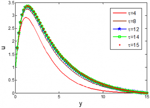
Figure 2. Time-sensitivity on u for different values of maximum time $\tau $
At first, the time-sensitivity test for different values of maximum time τ has been performed to find the admissible time at the steady-state solutions. The results are carried out for different maximum time $t=4,\,8,\,12,\,14$ and 15 with time increment $\Delta t=0.001\,$on the velocity $u$ which is shown in Figure 2. It has been observed that the velocities are very minimal changes for the time step t =14 and 15, therefore the steady-state solutions are considered for the admissible time t=15 with time increment$\Delta t=0.001\,$. The same situation has been found for the other distributions.
4.1 Velocity distributions
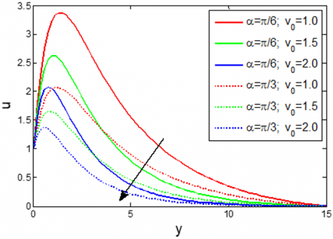
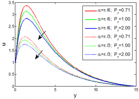
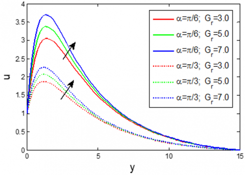
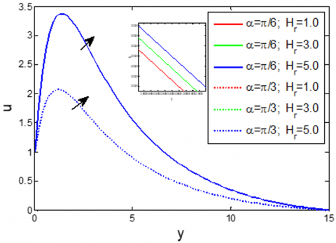
Figure 3 depicts the influence of effective inclined angle$\alpha $ on the velocity $u$, it has been found that the velocity decreases with the increase of $\alpha $. It is claimed that the velocity in x-direction is increased when $\alpha =0$ i.e. when the plate is properly vertical. The velocity has been increasing effect with the increase of $\eta $, which is shown in Figure 4. The influence of the microrotation parameter R on the velocity has been shown in Figure 5, Notice that near the plate u decreases with the increase of R, thereafter a few distances$(y>4.0\,\,\text{approx}\text{.)}$it has a very minor increasing effect. Also from Figure 6-7, it is found that u decreases with the increase of ${{v}_{0}}$ and ${{P}_{r}}$. Whereas, the velocity has an increasing with the increasing values of ${{G}_{r}}$ and K, which has shown in Figure 8 and Figure 9 respectively. It is found from Figure 10 that the velocity has very minor increasing effects with the increase of ${{H}_{r}}$.
Figure 3. Velocity distribution on $u$ for different values of inclined angle $\alpha $
Figure 4. Velocity distribution on u for different values of boundary parameter $\eta $
Figure 5. Velocity distribution on u for different values of microrotation parameter R
Figure 6. Velocity distribution on u for different values of Suction parameter ${{v}_{0}}$
Figure 7. Velocity distribution on u for different values of Prandtl number ${{P}_{r}}$
Figure 8. Velocity distribution on u for different values of Grashof number ${{G}_{r}}$
Figure 9. Velocity distribution on u for different values of Permeability parameter K
Figure 10. Velocity distribution on u for different values of Hartmann number ${{H}_{r}}$
4.2 Microrotation distributions
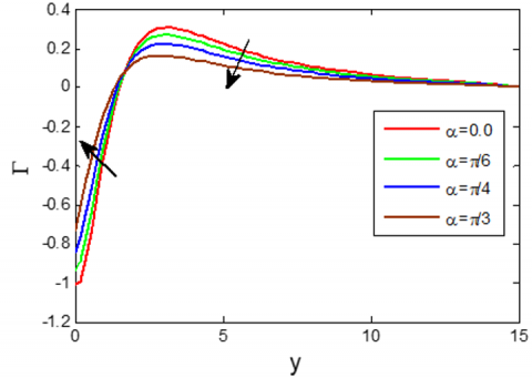
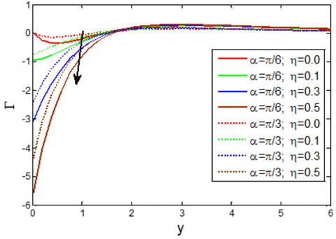
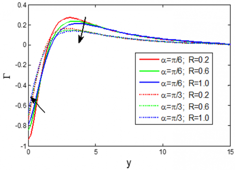
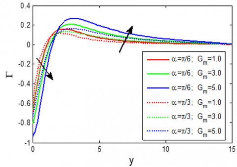
Figures 11-16 exhibit that the cross flow are shown in all the microrotation distributions. Figure 11 displays the microrotation$\Gamma $increases in$0\le y\le 1.6$ (approx.) with the increase of inclined angle α, thereafter it has a decreasing effect. Figure 12 indicates that the effect of boundary parameter on microrotation $\eta $on$\Gamma $. It is observed that microrotation has started minimum negative value with increasing values of$\eta $. Figure 13-14 indicate that $\Gamma $increases near the plate with the increase of R thereafter it decreases in a few regions. But Figures15-16 notice that the microrotation has reversed effect of Figures 13-14.
Figure 11. Microrotation distribution on $\Gamma $ for different values of inclined angle $\alpha $
Figure 12. Microrotation distribution on $\Gamma $for different values of boundary parameter on microrotation $\eta $
Figure 13. Microrotation distribution on $\Gamma $for different values of microrotation parameter R
Figure 14. Microrotation distribution on $\Gamma $ for different values of Suction parameter ${{v}_{0}}$
Figure 15. Microrotation distribution on $\Gamma $ for different values of mass Grashof number ${{G}_{m}}$
Figure 16. Microrotation distribution on $\Gamma $for different values of Permeability parameter K
4.3 Temperature and concentration distributions
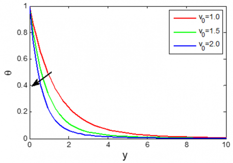
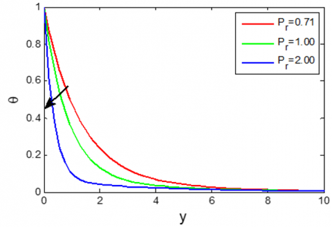
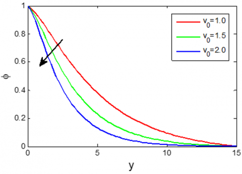
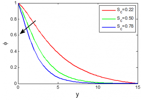
Figure 17 depicts the influence of effective inclined angle$\alpha $ on the fluid temperature $\theta$ (or concentration $\varphi$). It has been observed from the figure that there are no variations of $\theta$ (or $\varphi$) with the increase of $\alpha$. From Figure 18-19, it has been investigated that the temperature is decreased with the increase of ${{v}_{0}}$and ${{P}_{r}}$whereas the temperature is increased with the increase of ${{D}_{f}}$, which has been shown in Figure 20. Concentrations are decreased with the increase of ${{v}_{0}}$and${{S}_{c}}$, but it has an increasing effect with the increase of ${{S}_{0}}$, these are shown in Figures 21-23 respectively.
Figure 17. Temperature θ or Concentration φ distributions for different values of $\alpha $
Figure 18. Temperature distribution θ for different values of Suction parameter ${{v}_{0}}$
Figure 19. Temperature distribution θ for different values of Prandtl number ${{P}_{r}}$
Figure 20. Temperature distribution θ for different values of Dufour number ${{D}_{f}}$
Figure 21. Concentration distribution φ for different values of Suction parameter${{v}_{0}}$
Figure 22. Concentration distribution φ for different values of Schmidt number ${{S}_{c}}$
Figure 23. Concentration distribution φ for different values of Soret number ${{S}_{0}}$
4.4 Local and average shear stress
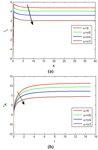
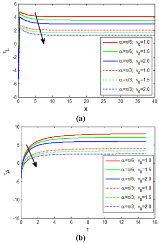
Figure 24. (a) Local Shear stress ${{\tau }_{L}}$ distributions for different values of inclined angle $\alpha$ (b) Average Shear stress ${{\tau }_{A}}$ for different values of inclined angle $\alpha $
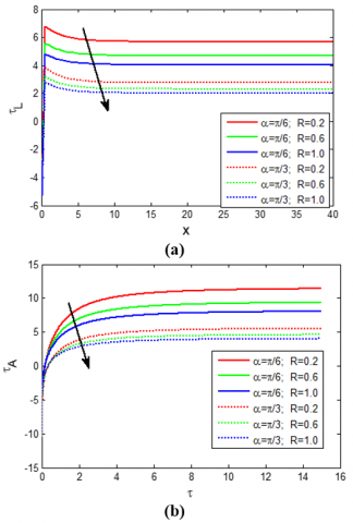
Figure 25. (a) Local Shear stress ${{\tau }_{A}}$ for different values of microrotation parameter R (b) Average Shear stress ${{\tau }_{A}}$ for different values of microrotation parameter R
Figure 26. (a) Local Shear stress ${{\tau }_{L}}$ for different values of Suction parameter ${{v}_{0}}$ (b) Average Shear stress ${{\tau }_{A}}$ for different values of Suction parameter ${{v}_{0}}$
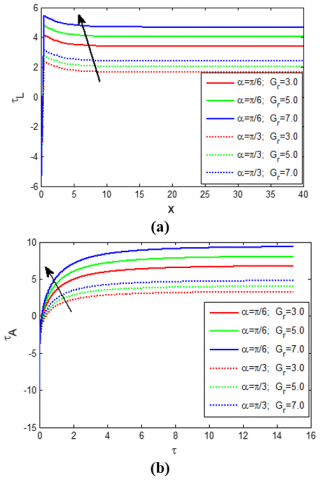
Figure 27. (a) Local Shear stress ${{\tau }_{L}}$ for different values of Grashof number${{G}_{r}}$ (b) Average Shear stress ${{\tau }_{A}}$ for different values of Grashof number ${{G}_{r}}$
Figures (a) and (b) of Figure 24-27 are represented the local shear stress ${{\tau }_{L}}$ and average shear stress ${{\tau }_{A}}$ respectively. Figure 24 depicts the effect of inclined angle $\alpha$ on the shear stress${{\tau }_{L}}$. It is explained that the local (or average) velocity gradient at the plate is decreased with the increase of$\alpha $. From Figure 25-26, it has been seen the shear stress ${{\tau }_{L}}\,(\text{or}\,{{\tau }_{A}})$ is also decreased with the increase of R and $v_{0}$. But from Figure 27, ${{\tau }_{L}}\,(\text{or}\,{{\tau }_{A}})$ is increased with the increase of ${{G}_{r}}$.
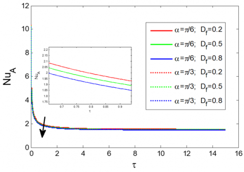
4.5 Average Nusselt number and Sherwood number
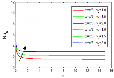
Figure 28. Average Nusselt number $N{{u}_{A}}$ distributions for different values of Suction parameter ${{v}_{0}}$
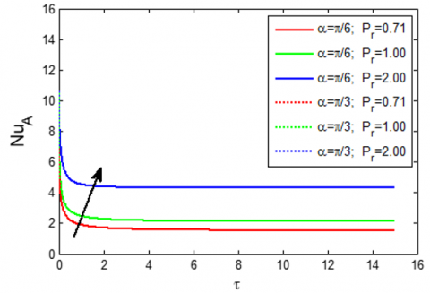
Figure 29. Average Nusselt number $N u_{A}$ distributions for different values of Prandtl number ${{P}_{r}}$
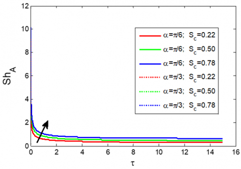
Figure 28 and Figure 29 exhibit the effects of Suction parameter ${{v}_{0}}$ and the Prandtl number ${{P}_{r}}$ on the Nusselt number $N{{u}_{L}}$ respectively. It has been found from both figures that the concentration gradient at the plate is increased with the increase of $v_{0}$ and $P_{r}$. But Figure 30 indicates that $N{{u}_{L}}$ is decreased with the increase of${{D}_{f}}$. On the other hand, Sherwood Number $S{{h}_{L}}$ is increased with the increase of ${{S}_{c}}$, but it has a decreasing effect with the increase of ${{S}_{0}}$, which are shown in Figure 31 and Figure 32.
Figure 30. Average Nusselt number $N{{u}_{A}}$ distributions for different values of Dufour number ${{D}_{f}}$
Figure 31. Average Sherwood number $S{{h}_{A}}$ distributions for different values of Schmidt number ${{S}_{c}}$
Figure 32. Average Sherwood number $S{{h}_{A}}$ distributions for different values of Soret number ${{S}_{0}}$
The micropolar fluid flow along with an inclined Riga plate through a porous medium has been studied. The angle of inclination, the effect of patient parameters on velocity, microrotation, temperature and concentration as well as on Skin friction, Nusselt number and Sherwood number have been analyzed. The content of the study is summarized as follows:
(1) Velocity u is retarded with the increasing values of $\alpha $, R, ${{v}_{0}}$ and${{P}_{r}}$, while it dominates with the increase of $\eta $,${{H}_{r}}$, K and ${{G}_{m}}$.
(2) Microrotation $\Gamma $ has a cross flow with $0\le \eta \le 0.1$. For this value of $\Gamma $ is increased in the 1st portion (near the plate) with the increase of $\alpha $, R, ${{v}_{0}}$and then it is retarded, while it has been shown a reverse effect with the increase of K and ${{G}_{m}}$.
(3) Temperature $\theta $ is improved with the increase of ${{D}_{f}}$, whereas it has a decreasing effect with the increase of ${{v}_{0}}$ and ${{P}_{r}}$.
(4) Concentration φ is dominated with the increase of ${{S}_{0}}$ whereas it has retarded with the increase of ${{v}_{0}}$ and ${{S}_{c}}$.
(5) Shear stress ${{\tau }_{L}}$ and ${{\tau }_{A}}$ illustrate the same behaviour of u with respective parameters. On the other hand, Nusselt number $N{{u}_{A}}$ and Sherwood number $S{{h}_{A}}$ depict the reverse effects of θ and φ, which are explained the natural behaviour of the Shear stress, Nusselt number and Sherwood number.
|
$\mathbf{J}$ |
Current density |
|
$\mathbf{B}$ |
Magnetic induction |
|
$\mathbf{E}$ |
Electrostatic field |
|
${{M}_{0}}$ |
Magnetization of the permanent magnets |
|
$l$ |
Width of magnets and electrodes |
|
${{J}_{0}}$ |
Current density |
|
$g$ |
Acceleration due to the gravity |
|
${{D}_{m}}$ |
Mass diffusion coefficient |
|
$\tilde{u}\,,\,\tilde{v}\,,\,\tilde{w}$ |
Dimensional velocity components in$\tilde{x}$-axis,$\tilde{y}$-axis and$\tilde{z}$-axis |
|
$\tilde{T}$ |
Temperature of the fluid |
|
${{\tilde{T}}_{w}}$ |
Constant temperature near the plate |
|
${{\tilde{T}}_{\infty }}$ |
Temperature outside of the boundary layer |
|
$\tilde{C}$ |
Concentration in the fluid |
|
${{\tilde{C}}_{w}}$ |
Constant concentration near the plate |
|
${{\tilde{C}}_{\infty }}$ |
Concentration outside of the boundary layer |
|
$u\,,\,v\,,\,w$ |
Dimensionless velocity component in x-,y- and z-axis |
|
$t$ |
Dimensionless time |
|
$\Delta t$ |
Time increment |
|
${{H}_{a}}$ |
Hartmann number |
|
${{G}_{r}}$ |
Thermal Grashof number |
|
${{G}_{m}}$ |
Mass Grashof number |
|
${{P}_{r}}$ |
Prandtl number |
|
${{S}_{c}}$ |
Schmidt number |
|
${{D}_{f}}$ |
Dufour number |
|
$N{{u}_{L}}$ |
Local Nusselt number |
|
$S{{h}_{L}}$ |
Local Sherwood number |
|
$N{{u}_{A}}$ |
Average Nusselt number |
|
$S{{h}_{A}}$ |
Average Sherwood number |
|
${{\tau }_{L}}$ |
Local shear stress |
|
${{\tau }_{A}}$ |
Average shear stress |
|
Greek symbols |
|
|
$\alpha $ |
Inclined angle, |
|
$\beta $ |
Volumetric coefficient of thermal expansion |
|
${{\beta }^{*}}$ |
Volumetric coefficient of mass expansion |
|
$\rho $ |
Density of the fluid |
|
$\sigma $ |
Conductivity of the fluid |
|
$\tau $ |
Maximum time |
|
${{k}_{T}}$ |
Thermal diffusion ratio |
|
$\upsilon $ |
Kinematic viscosity of the fluid |
|
$\mu $ |
Coefficient of viscosity of the fluid |
|
$\theta $ |
Dimensionless temperature |
|
$\varphi $ |
Dimensionless fluid concentration |
[1] Eringen, A.C. (1972). Theory of thermo micropolar fluids. Journal of Mathematical Analysis and Applications, 38(2): 480-496. https://doi.org/10.1016/0022-247X(72)90106-0
[2] Gorla, R.S.R. (1992). Mixed convection in a micropolar fluid from a vertical surface with uniform heat flux. International journal of Engineering Science, 30(3): 349-358. https://doi.org/10.1016/0020-7225(92)90080-Z
[3] Busuke, H., Tatsuo, T. (1969). Two-dimensional shear flows of linear micropolar fluids. International Journal of Engineering Science, 7(5): 515-522. https://doi.org/10.1016/0020-7225(69)90036-6
[4] Sheikh, N.A., Ali, F., Khan, I., Saqib, M., Khan, A. (2017). MHD flow of micropolar fluid over an oscillating vertical plate embedded in porous media with constant temperature and concentration. Mathematical Problems in Engineering. https://doi.org/10.1155/2017/9402964
[5] Hossain, M.A., Chowdhury, M.K. (1998). Mixed convection flow of micropolar fluid over an isothermal plate with variable spin gradient viscosity. Acta Mechanica, 131(3): 139-151. https://doi.org/10.1007/BF01177221
[6] Mansour, M.A., El-Hakiem, M.A., El Kabeir, S.M. (2000). Heat and mass transfer in magneto hydrodynamic flow of micropolar fluid on a circular cylinder with uniform heat and mass flux. Journal of Magnetism and Magnetic Materials, 220(2): 259-270. http://dx.doi.org/10.1016/S0304-8853(00)00488-1
[7] Mohamed, I.A., Othman Zaki, S.A. (2008). Thermal instability in a rotating micropolar viscoelastic fluid layer under the effect of electric field. Mechanics and Mechanical Engineering, 12(2): 171-184.
[8] Sivarami Reddy, C., Ramachandra Prasad, V., Jayalakshmi, K. (2019). Numerical simulation of natural convection of micropolar fluid in a rectangular porous enclosure. IJITEE, 8(4S): 329-339.
[9] Gailitis, A., Leilausis, O. (1961). On a possibility to reduce the hydro dynamical resistance of a plate in an electrode. Appl. Magnetohydrodyn., 12: 143-146.
[10] Anjum, A., Mir, N.A., Farooq, M., Khan, M.I., Hayat, T. (2018). Influence of thermal stratification and slip conditions on stagnation point flow towards variable thicked Riga plate. Results in Physics, 9: 1021-1030. https://doi.org/10.1016/j.rinp.2018.02.069
[11] Pantokratoras, A., Magyari, E. (2009). EMHD free-convection boundary-layer flow from a Riga-plate. Journal of Engineering Mathematics, 64(3): 303-315.https://doi.org/10.1007/s10665-008-9259-6
[12] Pantokratoras, A. (2011). The Blasius and Sakiadis flow along a Riga-plate. Progress in Computational Fluid Dynamics, An International Journal, 11(5): 329-333. https://doi.org/10.1504/PCFD.2011.042184
[13] Ahmad, A. (2019). Flow Control of non-Newtonain fluid using Riga plate: Reiner-Phillipoff and Powell-Eyring viscosity models. Journal of Applied Fluid Mechanics, 12(1): 127-133. https://doi.org/10.29252/jafm.75.253.28897
[14] Yücel, A. (1989). Mixed convection in micropolar fluid flow over a horizontal plate with surface mass transfer. International Journal of Engineering Science, 27(12): 1593-1602. https://doi.org/10.1016/0020-7225(89)90153-5
[15] Wahidunnisa, L., Subbarayudu, K., Suneetha, S. (2016). Effect of viscous dissipation over a Riga plate in a nano fluid with heat source/sink: A numerical study. International Journal of Technical Innovation in Modern Engineering & Science, 4: 1124.
[16] Iqbal, Z., Azhar, E., Mehmood, Z., Maraj, E.N. (2017). Melting heat transport of nanofluidic problem over a Riga plate with erratic thickness: Use of Keller Box scheme. Results in Physics, 7: 3648-3658. https://doi.org/10.1016/j.rinp.2017.09.047
[17] Iqbal, Z., Azhar, E., Mehmood, Z., Maraj, E.N. (2018). Unique outcomes of internal heat generation and thermal deposition on viscous dissipative transport of viscoplastic fluid over a Riga-plate. Communications in Theoretical Physics, 69(1): 68-76.
[18] Ayub, M., Abbas, T., Bhatti, M.M. (2016). Inspiration of slip effects on electromagnetohydrodynamics (EMHD) nanofluid flow through a horizontal Riga plate. The European Physical Journal Plus, 131(6): 131. https://doi.org/10.1140/epjp/i2016-16193-4
[19] Harutha, A., Devasena, Y. (2016). MHD mixed convection flow of a micropolar fluids through porous medium towards a stagnation, point on a vertical porous surface. IOSR Journal of Mathematics, 12: 32-37.
[20] Shamshuddin, M.D., Thumma, T. (2019). Numerical study of a dissipative micropolar fluid flow past an inclined porous plate with heat source/sink. Propulsion and Power Research, 8(1): 56-68. https://doi.org/10.1016/j.jppr.2019.01.001
[21] Subhas, A., Veena, P. (1998). Visco-elastic fluid flow and heat transfer in a porous medium over a stretching sheet. International Journal of Non-Linear Mechanics, 33(3): 531-540. https://doi.org/10.1016/S0020-7462(97)00025-5
[22] Rajput, U.S., Gupta, N.K. (2016). Dufour effect on unsteady free convection MHD flow past an exponentially accelerated plate through porous media with variable temperature and constant mass diffusion in an inclined magnetic field. IRJET, 3(8): 2135-2140.
[23] Angirasa, D., Peterson, G.P. (1997). Natural convection heat transfer from an isothermal vertical surface to a fluid saturated thermally stratified porous medium. International Journal of Heat and Mass Transfer, 40(18): 4329-4335. https://doi.org/10.1016/S0017-9310(97)00081-1
[24] Pattnaik, J.R., Dash, G.C., Singh, S. (2017). Radiation and mass transfer effects on MHD flow through porous medium past an exponentially accelerated inclined plate with variable temperature. Ain Shams Engineering Journal, 8(1): 67-75. https://doi.org/10.1016/j.asej.2015.08.014
[25] Daniel, S., Daniel, Y.S. (2013). Convective flow two immiscible fluids and heat transfer with porous along an inclined channel with pressure gradient. Research Inventy: International Journal of Engineering and Science, 2(4): 12-18.
[26] Hanvey, R.R., Khare, R.K., Paul, A. (2017). MHD flow of incompressible fluid through parallel plates in inclined magnetic field having porous medium with heat and mass transfer. IJSIMR, 5(4): 18-22.
[27] Nadeem, S., Malik, M.Y., Abbas, N. (2020). Heat transfer of three-dimensional micropolar fluid on a Riga plate. Canadian Journal of Physics, 98(1): 32-38. https://doi.org/10.1139/cjp-2018-0973