Mohammed Amine Amraoui
© 2021 IIETA. This article is published by IIETA and is licensed under the CC BY 4.0 license (http://creativecommons.org/licenses/by/4.0/).
OPEN ACCESS
Flat air solar collectors are used for heat transfer between the absorber and the heat transfer fluid, to improve this transfer there are several methods. Among these methods, the exchange surface lengthening and the creation of turbulence. In this work is done to give a comparison between two types of solar collectors, so we have made an improvement of Ben Slama Romdhane's solar collector by creating two air flow passages to increase heat transfer. We made a 3D simulation of a flat air solar collector with transverse baffles which causes turbulence and increases the exchange surface; we use the ANSYS calculation code to make the simulation and gives results with a brief time and minimal cost.
solar collector with double paths, thermal transfer, k_ε turbulent model, CFD
A flat air solar collector is a device designed to receive solar energy transmitted by radiation and transmit it to the heat transfer fluid. This article presents the study of the flow in the air stream of a solar collector and heat transfer between the absorber and the air, we used the CFD to realize and simulate a flat solar collector with air. We validated the CFD results by the Ben Slama Romdhane model. Flat solar collector with baffles as turbulence promoters thus promoting better heat transfer between the absorber and heat transfer fluid (air). The objective of this work is to make a three-dimensional study of a new model planar air collector with baffles and more than that a double flow path to give a better heat exchange and increased the efficiency of the solar collector, so we divided the air flow in two parts each part has a flow path. The turbulence model K-ε is used for the resolution of Navier-Stokes equations to study the distribution of temperature and speed in the air stream of this new planar air solar collector.
There are several works built to provide solutions that improve the performance of the flat air solar collector. Amraoui and Aliane [1] have done a digital study of solar col-lector created by Ben Slama Romdhane. because of the solutions is not feasible because of the limitations and the very expensive cost they passed from experimental work to the work of simulation by the code of calculation ANSYS, therefore the CFD gives very clear results with very complex situation, they did a numerical study of a planar solar air collector with turbulence promoters "transverse baffles", they started with the validation between the experimental results and the numerical results.
Batrak and Oztop [2] carried out an experimental study to do a thermodynamic study of a flat air solar collector; they created porous obstacles with two different thicknesses in the solar collector. The material used for the obstacles is aluminum. They tested four solar air collectors, they concluded that the efficiency of the collector increases by increasing the absorber surface area and the air flow and they found that the solar air collectors with obstacles give a better efficiency compared to barrier-free solar collectors.
One of the main problems in the use of solar energy is the low heat exchange with air in the dynamic vein of the solar collector. On the other hand, the introduction of baffles (obstacles) arranged in rows in the conduits of these systems clearly improves heat transfers. the work of Amraoui and Aliane [3] added roughness at the level of the insulation allowing to increase the exchange surface and consequently giving the fluid particles a very important trajectory to capture the maximum of energy. A numerical study is made using the "Fluent" calculation code to study the dynamic and thermal behavior of the air flow in these different flat solar collectors (flat solar collector fitted with baffles without roughness, with rectangular roughness, with triangular roughness, with circular roughness).
Amraoui and Aliane [4] have made a study of a solar flat plate collector by three-dimensional simulation (CFD) which reduces time and costs, the objective of this work is to compare the results theoretically by the results experimentally to validate the results obtained by the simulation and afterwards they made a study of an air flow in a solar air sensor equipped with transverse and longitudinal baffles to improve heat transfer, they gave results on the distribution of temperature, speed and turbulence on the air stream of the solar collector.
In order to improve the thermal performance of the solar collector, Labed et al. [5] have introduced very thin metallic artificial roughness 0.4 mm thick into the air stream, the geometry of which is in the form of a trapezoidal base channel. The addition of these baffles increases the area of convective exchange. In addition to the exchange with the absorbent plate, they had another additional exchange surface due to the channels placed horizontally in the direction of the air flow. The article contributes to the study of optimizing the performance of air-cooled solar collectors which constitute the second part of solar energy converters. According to the study conducted, the very favorable role in increasing heat exchange due to the presence of this type of baffles placed in the air stream. However, it is certainly true that these baffles generate pressure drops compared to a smooth channel.
The air collector studied by Oudjedi et al. [6] is a single-pass sensor, it has a window to pass the radiation and a black plate to absorb the solar energy. they have made equations of energy balance of the various components of the sensor and a modeling of the coefficients of heat exchange and end they gave results on the hourly values of the global radiation, the ambient temperature and the ambient relative humidity for the site of Adrar in addition the distribution of temperature and the speed in the solar collector plane with air with the change of the height of the collector.
Nowzari et al. [7] changed the absorber plate by fourteen steel of wire layers mesh, 0.2 × 0.2 cm in cross-section, and they were fixed in the duct parallel to the glazing for a heater double pass solar air, they tested for its thermal efficiency in a geographical location of Cyprus in the city of Famagusta, they concluded that the efficiency increases with the increase in mass flow but the temperature difference of the inlet and the outlet decreased due to the increase in mass flow. The average daily solar intensity is 730.3 W / m2.
In the work of Kaoulal et al. [8], they were interested in the study of an air sensor intended for heating the building and to do this they established a mathematical model based on the method of thermal balances. The numerical simulation results in MATLAB allow you to discover the temperature profiles of each layer which constitutes the sensor to be studied (the glass, the absorber, etc.), as well as to assess the instantaneous yield according to the ACHRAE standard. To validate these theoretical results, they designed a prototype flat air sensor consisting of simple glass glazing which achieves the greenhouse effect necessary to heat the absorber which is based on copper, a layer of insulation behind the sensor, it allows better thermal performance, it is provided by polystyrene.
Semmar et al. [9] studied and designed a solar sensor for hot air production using a computer program using a mathematical model where all the parameters characterizing the performance of the system are evaluated instantly during the period of sunshine. for the experimental consists in the realization of the considered model.
In the development of planar air collector’s tomorrow there are several methods to increase the heat exchange coefficient enters the air stream of air planar solar collector, we place wings to orient the green heat transfer fluid the plate "Absorber". Studies by Romdhane [10] have focused on the creation of turbulence promoters such as baffles to increase heat exchange and the fluid path. This article gives several types of solar air collectors produced by several researchers that they have given several ways of the location of the baffles in the solar collectors at the end of the article. Ben Salma presents the different efficiencies of the different flat solar air collectors.
The study by Benahmed and Aliane [11] presents the flow around the obstacles, they did the digital validation of 3D by the work of Hussein and Martinuzzi (1996). this work is a three-dimensional simu-lation using the ANSYS CFX calculation code to carry out a three-dimensional numerical simulation of turbulent flow around an obstacle with inclined upstream and downstream edges It has been explained that the satis-factory results have not been obtained using the k-ε and RNG k-ε methods and that the turbulence model k-ω SST gave better results after analyses as a function of time. The purpose of the work presented below is to study the influence of the inclined form of the two upper peaks of a rectangular cube.
A numerical study was carried out by Menni et al. [12] of a horizontal rectangular section channel with baffle in the form of diamond mounted on the lower plate, a 2D study that they presented several results, the fact of adding an obstacle on the lower plate increases the turbulence in the air stream so it is concluded that there is an increase in the heat exchange between the fluid and the plate. The second baffle role is the increased fluid path.
Jalil and Abdulkadhim in 2019 [13] did a study of a solar collector with rectangular micro-channels, they started with the experimental study and they gave several thermal results using thermal collectors for different point of air plane solar collector, in this article there is a detailed parametric study on the solar collector at the end of this work there is a numerical simulation of the air plane solar collector, the technique of micro-channels improves the thermal efficiency of the solar collector, they noticed that the experimental results are similar compared to the numerical results
The article by Moumeni and Bouchekima [14] presents a study of a vertical solar sensor with baffles to increase the turbulence, they used the CFD calculation code based on the finite volume method was implemented with the SIMPLE algorithm and the standard turbulence model (k - ε).
In the work of Valentín and Pacheco [15], two mathematical models were evaluated to simulate the operation of a flat plate solar air collector. The first model was called static and is characterized by not taking into account the effects of heat storage or conduction heat flow in the elements of the system. In order to implement this model, a system of non-linear equations has been proposed, solved numerically. by Newton's method, while the second model called dynamics, which takes these effects into account, was explicitly proposed and resolved. For the validation of the models, a flat plate solar air collector was built, on which a data acquisition system was then implemented, in order to record the operating parameters of the collector, such as: the flow d air inside the sensor, temperature of the back cover of the sensor, local environmental data, such as: environment temperature, solar radiation and wind speed, measured on a summer day between 8:00 am and 10:00 pm, in addition to the data of construction and properties of collector materials.
The main objective of the work of Jassim and Shbailat [16] to make a study on different type of air flow in solar air plant collectors, therefore by numerical simulation the authors have created five forms of the solar collectors to make a thermodynamic study and they gave several results on the distribution of temperature and speed for each type of solar collector air, the numerical study made by the code of calculation Ansys CFX with the choice of the turbulence K- ε, this article presents governing equations for solar collectors.
The article by Karime and Amin [17] presents a comparative study of two types of air plane solaires, one with flat absorber and the other with the V-shaped absorber, they used MATLAB to give the values of temperatures and the energetic equations to calculate the new temperatures, they concluded that the model with groove V gives a better thermal efficiency and they concluded that the flow rate greatly influences the efficiency of the flat air solar collector.
Tchaya et al. [18] present a study of an indirect solar drier, they developed a mathematical model using MATLAB software to calculate the energy of the solar drier, they validated this model by several experimental works, article presents several results on temperature versus time. They concluded that the speed is a very essential parameter to control the output temperature, to ensure a good efficiency of the solar collector it is necessary a thermal resistance between the absorber and the insulator equal to 0.025 W –1.m2. K.
In this article by Khorasanizadeh et al. [19] presents a study of flat air collectors with different absorbent plates (triangle, rectangle and sinuous undulations), they concluded that the corrugated model gives perfect results for the whole year. For the sinusoidal model gives a better performance compared to the other model. The collector with sinusoidal plate adsorbent plate has the highest amount of PEC throughout the year. The results show that in terms of temperature increase from inlet to outlet and the highest performance evaluation criterion, the optimal Reynolds geometry for all studied geometries is 2500.
In this study by Mohseni et al. [20], the combined heat transfer of natural and radiant displacements in a flat solar collector in two-dimensional mode by considering the water channel under the adsorbent plate was studied. The results showed that with the increase in the air absorption coefficient, the temperature of the air between the glass and the adsorbent plate increases, while the temperature of the adsorbent plate and consequently the temperature of the water coming out of the collector decreases. However, the effect of the adsorption coefficient on the air temperature is greater than its effect on the temperature of the adsorbent plate. Therefore, if the solar collector is used as a solar water heater, due to the small effect of the absorption coefficient on the efficiency of the water heater, in this case, calculations related to the environment involved in the radiation can be ignored and only surface-to-surface radiation can be taken into account. However, if the collector is used as heating air, due to the efficiency of the air absorption coefficient, especially for cities with high humidity, calculations related to the environment involved in the radiation must be taken into account.
The article by Laaraba and Khechekhouche [21] presents a study of a natural flow in a flat air solar collector fitted with baffles placed on the glass, this collector placed vertically, the object of this article is the study of the influence baffles in the thermal efficiency of the flat air solar collector. They concluded that the increase in the baffles decreased the value of average Nusselt therefore decrease in thermal losses to the outside, the optimal value of the height of the baffles is 0.4, the value of the height of the baffles more than 0.4 decreased the exchanged flow by convection.
Ramadhani et al. [22] present a study to improve the heat exchange in the solar drier, the authors carried out a comparative study between a flat air solar collector with a single passage, salary collector with double passage (flow parallel) and a solar collector with double passage (flow against current), the results show that the latter model gives better thermal efficiency. So, they noticed that the value of the efficiency of the double duct countercurrent sensor equals 38.2% i.e., an improvement of 8.3% compared to a single duct sensor, they concluded that the double duct counter-current sensor has a large exchange surface therefore an increase in the heat exchange between the absorber and the heat transfer fluid.
The researchers in the field of the development of the solar air collector gave several works on the shapes of the baffles and their location in the solar collector to achieve a more efficient model, in our article we played on the positioning of the baffles to create two path of the air flow and ensures better heat transfer between the absorber and the air from the inlet of the solar collector to the outlet.
We developed the model of Ben Slama Romdhane it is a model with transverse baffles to increase the flow path but the disadvantage of these baffles is the increase in the air circulation time in the flat solar collector air and there are very important dead zones, so we created a model with transverse baffles and with two flow paths to increase the exchange surface and improve the heat transfer between the absorber and the coolant and reduces the air circulation time in the flat air solar collector, more than that we have reduced the dead zones by the increase of the turbulence.
we have given our geometry of the flat air solar collector using the code of the "Ansys" calculator and we have validated our results by the results of Ben Salma Romdhane for the reliability of our work, afterwards we gave governing equations used by the calculator code "Ansys", we made a parametric study of the flat air solar collector and afterwards we gave results on the temperature field, the speed and the distribution of the turbulence in the solar collector and We made a comparison between our model and the model of ben salma Romdhane, at the end we concluded our work by presenting the important results.
2.1 Geometry
The first flat air solar collector they designed without obstacles but they have low efficiency, the researchers developed the heat transfer in the solar collector by adding baffles to the fluid stream to increase the flow path and created turbulence, among these researchers we have the work of ben Slama Romdhane. he put transverse baffles above the insulation to increase the efficiency of the solar collector, but the drawback is the increase in air circulation time in the air stream and creation of dead zones important.
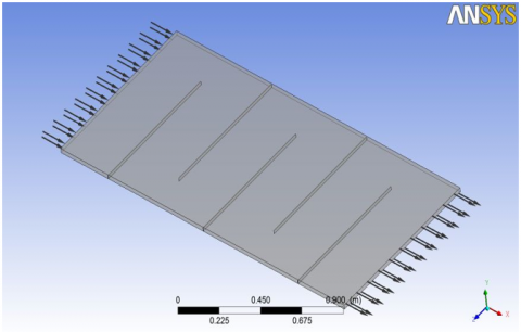
In this work, we have improved the model of ben Slama Romdhane (Figure 1), so we have created a two-passage model of air (Figure 2), to reduce air circulation time in the solar collector and reduce dead zones.
A solar air collector with air with 2 meters in length and 1 meter in width, the collector comprises transverse baffles which lets pass the air flow through a space of 20% of the width of the solar collector see Figure 2.
The length of large baffles is 800 mm and the small baffles is 400 mm. The space between the baffles is 333 mm.
The height of the baffles occupies the entire height of the air plane solar collector air stream which is equal to 25 mm.
Figure 1. Collector Ben Slama Romdhane model provided with baffles not touching the absorber
Figure 2. Collector our model provided with baffles touching the absorber
2.2 Governing equations
(1) The Mass Conservation Equation:
The equation for conservation of mass, or continuity equation, can be written as follows:
$\nabla .(\rho \vec{v})=0$ (1)
$\frac{\partial}{\partial x}\left(\rho v_{x}\right)+\frac{\partial}{\partial y}\left(\rho v_{r}\right)+\frac{\rho v_{r}}{r}$ (2)
(2) Momentum Conservation Equations:
Conservation of momentum is described by:
$\nabla .(\rho \vec{v} \vec{v})=-\nabla p+\nabla(\bar{\bar{\tau}})+\rho \vec{g}$ (3)
$\rho \vec{g}$ The gravitational body force.
The stress tensor $\bar{\bar{\tau}}$ is given by
$\bar{\bar{\tau}}=\mu\left[\left(\nabla \vec{v}+\nabla \vec{v}^{T}\right)-\frac{2}{3} \nabla . \vec{v} I\right]$ (4)
The second term on the right hand side is the effect of volume dilation.
The axial and radial momentum conservation equations are given by:
$\frac{1}{r} \frac{\partial}{\partial x}\left(r \rho v_{x} v_{x}\right)+\frac{1}{r} \frac{\partial}{\partial r}\left(r \rho v_{r} v_{x}\right)=-\frac{\partial p}{\partial x}+$
$\frac{1}{r} \frac{\partial}{\partial x}\left[r \mu\left(2 \frac{\partial v_{x}}{\partial x}-\frac{2}{3}(\nabla \cdot \vec{v})\right)\right]+\frac{1}{r} \frac{\partial}{\partial r}\left[r \mu\left(\frac{\partial v_{x}}{\partial r}+\frac{\partial v_{r}}{\partial x}\right)\right]$ (5)
$\frac{1}{r} \frac{\partial}{\partial x}\left(r \rho v_{x} v_{r}\right)+\frac{1}{r} \frac{\partial}{\partial r}\left(r \rho v_{r} v_{r}\right)=-\frac{\partial p}{\partial r}+$
$\frac{1}{r} \frac{\partial}{\partial x}\left[r \mu\left(\frac{\partial v_{r}}{\partial x}+\frac{\partial v_{x}}{\partial r}\right)\right]+\frac{1}{r} \frac{\partial}{\partial r}\left[r \mu\left(2 \frac{\partial v_{r}}{\partial r}-\frac{2}{3}(\nabla . \vec{v})\right)\right]-$
$2 \mu \frac{v_{r}}{r^{2}}+\frac{2}{3} \frac{\mu}{r}(\nabla . \vec{v})+\rho \frac{v_{Z}^{2}}{r}$ (6)
where, $\nabla . \vec{v}=\frac{\partial v_{x}}{\partial x}+\frac{\partial v_{r}}{\partial r} \frac{v_{r}}{r}$ and $v_{Z}$ is the swirl velocity.
$\frac{1}{r} \frac{\partial}{\partial x}(r \rho u w)+\frac{1}{r} \frac{\partial}{\partial r}(r \rho v w)=\frac{1}{r} \frac{\partial}{\partial x}\left[r \mu \frac{\partial w}{\partial x}\right]+$
$\frac{1}{r^{2}} \frac{\partial}{\partial r}\left[r^{3} \mu \frac{\partial}{\partial r}\left(\frac{w}{r}\right)\right]-\rho \frac{v w}{r}$ (7)
where x is the axial coordinate, r is the radial coordinate, u is the axial velocity, v is the radial velocity, and w is the swirl velocity.
The Energy Equation:
$\nabla .(\vec{v}(\rho E+p))=\nabla .\left(k_{\mathrm{eff}} . \nabla \mathrm{T}-\sum_{\mathrm{j}} \mathrm{h}_{\mathrm{j}} . \overrightarrow{\mathrm{J}}_{\mathrm{j}}+\left(\bar{\bar{\tau}}_{\mathrm{eff}} . \vec{v}\right)\right)$ (8)
The first three terms on the right-hand side of Eq. (8) represent energy transfer due to conduction, species diffusion, and viscous dissipation, respectively.
$k_{\mathrm{eff}}=k^{\prime}+\frac{c_{p} \mu_{t}}{P r_{t}}$ (9)
The default value of the turbulent Prandtl number is 0.85.
$E=h^{\prime}-\frac{p}{\rho}+\frac{v^{2}}{2}$ (10)
$h^{\prime}=\sum_{j} Y_{j} h_{j}+\frac{p}{\rho}$ (11)
$h_{j}=\int_{T_{r e f}}^{T} c_{p . j} d T$ (12)
where $T_{\text {ref }}$ 298.15 K.
Transport Equations for the Standard k-ε Model:
The turbulent kinetic energy, k, and its turbulent eddy dissipation, ε, are obtained from the following transport equations:
It is a two-equation model that provides a general description of turbulence using two transport equations, one for turbulent kinetic energy (k) and the other for dissipation (epsilon). Turbulent dissipation is the rate at which speed fluctuations dissipate. The coefficients are derived empirically; Valid only for turbulent flows. In the standard k-ε model, the turbulent viscosity is determined from a single turbulence length scale, so that the calculated turbulent diffusion is that which occurs only at the specified scale, when in reality all the motion scales will contribute to the turbulent diffusion. The k-ε model uses the gradient diffusion hypothesis to relate the Reynolds stresses to the gradients of mean velocity and to the turbulent viscosity. This model is not very efficient for currents involving a reverse pressure gradient, separation, strong curvature of the pipes.
$\frac{\partial}{\partial x_{i}}\left(\rho k u_{i}\right)=\frac{\partial}{\partial x_{j}}\left[\left(\mu+\frac{\mu_{t}}{\sigma_{k}}\right) \frac{\partial k}{\partial x_{j}}\right]+G_{k}-\rho_{\varepsilon}$ (13)
$\frac{\partial}{\partial x_{i}}\left(\rho \varepsilon u_{i}\right)=\frac{\partial}{\partial x_{j}}\left[\left(\mu+\frac{\mu_{t}}{\sigma_{\varepsilon}}\right) \frac{\partial \varepsilon}{\partial x_{j}}\right]+C_{1 \varepsilon} \frac{\varepsilon}{k} G_{k}-C_{2 \varepsilon} \rho \frac{\varepsilon^{2}}{K}$ (14)
The term $G_{k}$, representing the production of turbulence kinetic energy,
$G_{k}=-\rho \overline{u_{l}^{\prime} u_{j}^{\prime}} \frac{\partial u_{j}}{\partial x_{i}}$ (15)
(3) Modeling the Turbulent Viscosity:
The turbulent (or eddy) viscosity, $\mu_{t}$ is computed by combining k and ε as follows:
$\mu_{t}=\rho . C_{\mu} \frac{k^{2}}{\varepsilon}$ (16)
where $C_{\mu}$ is a constant.
Model Constants:
The model constants $C_{1 \varepsilon}, C_{2 \varepsilon}, C_{\mu}, \sigma_{k}$ and $\sigma_{\varepsilon}$ have the following default values:
$C_{1 \varepsilon}=1.44, C_{2 \varepsilon}=1.92, C_{\mu}=0.99, \sigma_{k}=1.0, \sigma_{\varepsilon}=1.3$.
2.3 Collector study
A flat air solar collector transforms the solar radiation energy by a thermal energy absorbed by the heat transfer fluid "air”; therefore, a flow of air enters the flat air solar collector by a temperature $T_{1}$ and follows an x axis up to at the output of the solar collector by a temperature $T_{2}$.
$\varphi_{0} . \ell . L=\rho . c_{p} . q_{v}\left(T_{2}-T_{1}\right)$ (17)
ρ: average density of air ρ =1.25 kg⁄m3
$c_{p}$: average mass heat of air $c_{p}$=1000 j⁄(kg℃)
an air flow by abscissa x with an average temperature T, we take an element of air xx we have:
Power received by the collector:
$\varphi_{0} . \ell . d x$ (18)
Power carried by the fluid:
$\rho . c_{p} . q_{v} . d T=h . \ell . d x\left(T_{p}-T\right)$ (19)
We present h by the following equation:
$\frac{h . d H}{\lambda}=N u$ (20)
$e \ll \ell$, so $d H=2 e$.
The power lost by conduction to the insulating part:
$\frac{\lambda_{i}}{E_{i}} . \ell . d x\left(T_{p}-T_{e}\right)$ (21)
We will have a steady state:
$\rho . c_{p} . q_{v} . d T=\frac{\lambda . N u}{2 e} \cdot \ell . d x\left(T_{p}-T\right)=\varphi_{0} . \ell . d x-$
$\frac{\lambda_{i}}{E_{i}} . \ell . d x\left(T_{p}-T_{e}\right)$ (22)
We solve these equations so we eliminate $T_{p}$; at the end we conclude the differential equation:
$\frac{d T}{\varphi_{0}+\frac{\lambda_{i}}{E_{i}} .\left(T_{e}-T\right)}=\frac{\ell . d x}{\rho . c_{p} . q_{v}\left(1+\frac{\lambda_{i}}{E_{i}} . \frac{2 e}{\lambda . N u}\right)}$ (23)
Let's integrate this relationship between entry and exit:
$\int_{T_{e}}^{T_{2}} \frac{d T}{\varphi_{0}+\frac{\lambda_{i}}{E_{i}} .\left(T_{e}-T\right)}=\int_{0}^{L} \frac{\ell \cdot d x}{\rho . c_{p} . q_{v}\left(1+\frac{\lambda_{i}}{E_{i}} . \frac{2 e}{\lambda . N u}\right)}$ (24)
$-\frac{E_{i}}{\lambda_{i}}\left[\ln \left(\varphi_{0}+\frac{\lambda_{i}}{E_{i}} .\left(T_{e}-T\right)\right)\right]_{T_{e}}^{T_{2}}=\frac{\ell . L}{\rho . c_{p} . q_{v}\left(1+\frac{\lambda_{i}}{E_{i}} . \frac{2 e}{\lambda . N u}\right)}$ (25)
From where the value of the temperature $T_{2}$ at the exit of the collector:
$T_{2}=T_{e}+\varphi_{0} \frac{E_{i}}{\lambda_{i}}\left[1-\exp \left(-\frac{\lambda_{i}}{E_{i}} . \frac{\ell_{i}}{\rho . c_{p} . q_{v}\left(1+\frac{\lambda_{i}}{E_{i}} . \frac{2 e}{\lambda . N u}\right)}\right)\right]$ (26)
$\Delta T=\varphi_{0} \frac{E_{i}}{\lambda_{i}}\left[1-\exp \left(-\frac{A}{1+B}\right)\right]$ (27)
with
$A=\frac{\lambda_{i} . \ell . L}{E_{i} . \rho . c_{p} . q_{v}}, B=\frac{\lambda_{i}}{E_{i}} . \frac{2 e}{\lambda . N u}$
When the insulation is perfect $\frac{\lambda_{i}}{E_{i}} \rightarrow 0$, and we fall back on the Eq. (17).
Finally, we obtain the performance of the flat air solar collector by the formula which equals the ratio between the two real powers and which supplied by the sun radiation:
$\eta=\frac{\rho . c_{p} . q_{v}\left(T_{2}-T_{1}\right)}{\varphi_{0} . \ell . L}$ (28)
$\eta=\frac{\rho . c_{p} . q_{v} E_{i}}{\lambda_{i} . \ell . L}\left[1-\exp \left(-\frac{\lambda_{i}}{E_{i}} . \frac{\ell . L}{\rho . c_{p} . q_{v}\left(1+\frac{\lambda_{i}}{E_{i}} . \frac{2 e}{\lambda . N u}\right)}\right)\right]$ (29)
Ask,
$1 / A=\frac{\rho . c_{p} . q_{v} E_{i}}{\lambda_{i} . \ell . L}, \eta=\frac{1}{A}\left[1-\exp \left(-\frac{A}{1+B}\right)\right]$ (30)
2.4 The boundary conditions
We studied a model with two trajectories to increase the heat transfer see (Figure 2). to solve the previous governing equations for turbulent flow and the wall sliding condition is not applicable, we used the following boundary conditions:
The air flow is: 50 m3/hm2 which equals per speed unit: u0=0.014 m/s.
The temperature at the input of the flat air solar collector is: Te =300 K.
The turbulent kinetic energy at the input of the flat air solar collector is: $k=0,005 . U_{0}^{2}=9.645 .10^{-7} \mathrm{~m}^{2} / \mathrm{s}^{2}$.
The energy dissipation at the input of the flat air solar collector is: $\varepsilon=0,1 . k^{2}=9,3.10^{-14} \mathrm{~m}^{2} / \mathrm{s}^{3}$.
The temperature of the absorber: Tabs=380K.
The temperature of the insulation and the lower baffle: Tiso=340 K.
The outlet pressure: Ps=Patm..
The simplest of turbulence are two-equation models in which the solution of two separate transport equations allows the turbulent velocity and length scales to be determined independently. The standard k-ε model falls into this turbulence model and has become the spearhead of practical engineering flow calculations over time since it was proposed by Launder and Spalding. Robustness, economy and reasonable precision for a wide range of turbulent flows explain its popularity in industrial flow and heat transfer simulations. It is a semi-empirical model, and the derivation of the model equations is based on phenomenological considerations and empiricism. This model gives results very close to the result of Ben Slama Romdhane compared to other turbulence model.
2.5 Mesh
A mesh is the spatial discretization of a continuous medium. It is a fundamental step which conditions all the rest of the calculation, or also, to have results close to reality. a geometric modeling of a domain by finite and well-defined proportional elements. The object of a mesh is to carry out a simplification of a system by a model representing this system and, possibly, its medium, with a view to simulations of calculations or graphic representations.
Several complicated meshes processed by Ansys which are in general imported directly from other "GAMBIT" mesh generation software, The operation consists of a number of nodes by drawing a grid on the compute domain is divided into control volume in finite and direct number, one says that one generates a mesh, The under fields obtained represent the volumes of control with four neighboring nodes by the four faces of the volume of control.
We used the non-uniform mesh using Ansys calculation code or even Figures 3 and 4. The use of the advanced size function is curvature, the center of relevance is fine, the initial element size is assembly active, smoothing is high, transition is slow and center of stroke angle is coarse. The number of elements is 1,327,560 and the number of nodes is 1,406,808.
Figure 3. 3D mesh of solar flat plate collector
Figure 4. 3D flat solar collector mesh zoom
We make a comparison between the numerical results CFD with the experimental results of Ben Slama Romdhane's solar collector model. I made the model of Ben Slama Romdhane by the Ansys calculator code and I output the results and I compared with the experimental results of Ben Slama Romdhane. I noticed that there is a good concordance of the results. Note that the difference between the experimental and simulated outlet temperature for different flow rates is close to 3°C (Table 1).
$N u=0,0158 R e^{0,8}$ (31)
$R e=\frac{V . d H .\rho}{\mu}$ (32)
$\eta=\tau \alpha-\frac{U\left(\left(T_{2}-T_{1}\right)\right)}{\varphi_{0}}$ (33)
If the air flow increases, the Nusselt number and the efficiency increase but the temperature difference decreases.
Table 1. Comparison of experimental and CFD results
|
Flow m3/hm2 |
Collector ΔT by CFD (℃) |
Collector Ben Slama Romdhane model ΔT(℃) [10] |
|
Q1=50 |
33 |
30.51 |
|
Q1=35 |
51 |
52.60 |
3.1 Temperatures field
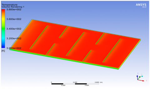
The temperature field is presented in Figure 5. we notice the air begins to heat from the input of the solar collector, the temperature is higher near the absorber. The heat transfer made due to conduction and convection, the air near the absorber is heated by convection mixes with the cold air due to the turbulence created by the baffles.
Figure 5. Temperatures field for the collector
3.2 The velocity vector V
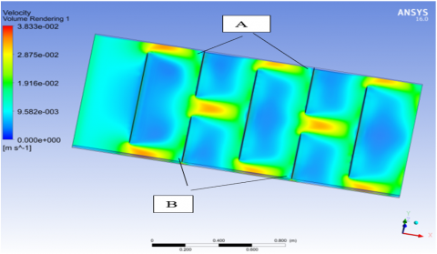
The speed distribution is shown in Figure 6. Two paths have been created for the fluid flow to increase the heat transfer between the absorber and the fluid. The speed reaches up to 0.03 m/s at the end of the baffles. In the areas at the end of the baffles there are recirculation areas and downstream of the baffles the speed is very low, the fluid accelerates in the areas of narrowing of the passage section, we also notice that there are small dead zones A and B.
3.3 The velocity components
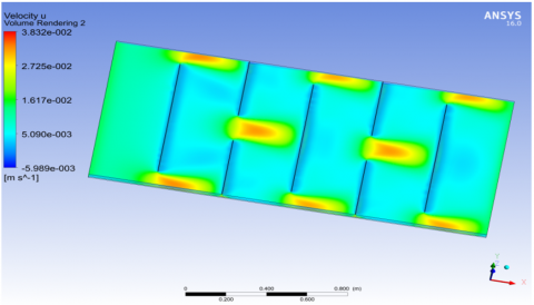
The addition of transversal baffles in a solar collector to increase the flow trajectory and improve heat transfer. In our model we have created two paths for flow so there is a big improvement in heat transfer, the speed at the end of the baffles is increased by more than twice the speed of entry (Figure 7). Around the baffles: these speeds are positive (in the same direction of flow) and negative in the opposite direction see (Figure 8). For Figure 9 the speed component w is homogeneous in all the solar collector air stream, it is the component of the speed V as a function of the Z axis.
Figure 6. Velocity distribution
Figure 7. The velocity component u
Figure 8. The velocity component v
Figure 9. The velocity component w
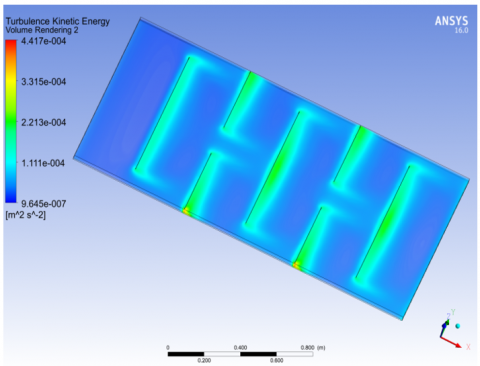
3.4 Turbulent kinetic energy (k)
Figure 10. Turbulent kinetic energy (k) distribution
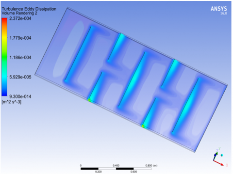
Figure 11. Turbulent eddy dissipation (ε) distribution
Figure 10 shows the distribution of the kinetic energy of turbulence, it is clear that the flow has a turbulent kinetic energy throughout their trajectory. Around the baffles the kinetic energy of turbulence takes on very important values.
3.5 Turbulent eddy dissipation (ε)
Figure 11 shows the distribution of the turbulent eddy dissipation (ε), it is clear that the flow has turbulent eddy dissipation (ε) throughout their trajectory. Around the baffles the turbulent eddy dissipation (ε) takes on very important values.
3.6 Temperatures profiles
The temperature profiles at the outlet of the solar collectors are shown in Figure 12. We note that there is a great improvement in thermal transfer for our model of solar collector; the average temperature reaches up to 360k.
$T_{\text {aver }}=\frac{\sum_{a=1}^{a=n}\quad T_{a}}{n}$ (34)
Figure 12. Temperatures profiles
The need to improve the thermal performance of the flat plate solar collector, for specific needs, prompted us to carry out this study. For this, we have made a study of an air flow in a solar collector air planes provided with transverse baffles, the transverse baffles increases the flow path and promotes the creation of turbulence zones which improves the exchange thermal within the solar collector, the 'choice of a location of the baffles in the solar collector influence the development of improvement the thermal change between the absorber and the fluid (air), so we have given the distribution of temperature and speed in the fluid stream of the solar collector to see the influence of the baffles in the air flow and we noticed that the value of the turbulent kinetic energy (k) and the turbulent dissipation energy (ε ) takes very important value close to the baffles, in the end we made a comparative study between the model of Ben Slama Romdhane with only one trajectory of the flux and our model with two trajectories of the flux. We therefore increased the surface of exchange for the heat transfer fluid even if we see that there is a significant turbulence compared to the first model all which shows that this last model gives a big improvement of the thermal transfer and an increased efficiency of the solar collector.
In our model we have reduced the dead zones created by the baffles but we cannot eliminate it, we also notice that the speed is very low when downstream of the baffles and there are recirculation zones at the end of the baffles. There is a lot of work that can be done on flat air solar collectors to solve these problems and improve their efficiency, in particular on the baffles, the insulation and the passage of air in the collector. It is therefore recommended that future work in this direction carry out the following steps:
(1) Vary the positions of the location of the baffles to see its effect on the results.
(2) Study the use of porous baffles in the fluid vein.
(3) Study of the influence of the thickness of the air stream.
(4) Study of the influence of thermal losses and their minimization according to different material of the insulation.
|
$c_{p}$ |
dimensionless heat source length Heat capacity at constant pressure, volume (J/kg.K) |
|
$C_{1 \varepsilon}$, $C_{2 \varepsilon}$ and $C_{\mu}$ |
constants |
|
dH |
hydraulic diameter of the section |
|
E |
the total energy (J) |
|
$E_{i}$ |
thickness of the insulation (m) |
|
e |
the thickness (m) |
|
$\vec{g}$ |
gravitational acceleration (m/s2) |
|
$G_{k}$ |
the generation of turbulence kinetic energy due to the mean velocity gradients |
|
$h^{\prime}$ |
sensible enthalpy (energy/mass) |
|
h |
the transfer coefficient between the absorbent wall and the fluid (W/m2 °C) |
|
I |
the unit tensor |
|
$\overrightarrow{\mathrm{J}}_{\mathrm{j}}$ |
the diffusion flux of species j |
|
$k^{\prime}$ |
the thermal conductivity (W/m.K) |
|
k |
the turbulent kinetic energy (m2/s2) |
|
$k_{\text {eff }}$ |
the effective conductivity |
|
L |
the length (along x) (m) |
|
ℓ |
the width of the flow (m) |
|
Nu |
Nusselt number of flow |
|
p |
the static pressure (pa) |
|
$P r_{t}$ |
the turbulent Prandtl numbers |
|
$q_{v}$ |
the air flow |
|
T |
temperature (K) |
|
$T_{e}$ |
outside temperature (equal to $T_{1}$) |
|
$T_{p}$ |
the temperature of the absorbent |
|
U |
overall losses coefficient (back of collector) (W/m2 K) |
|
$u_{i}$ |
flow velocity (m/s) |
|
V |
velocity magnitude (m/s) |
|
$\vec{v}$ |
overall velocity vector (m/s) |
|
$Y_{j}$ |
the mass fraction of species j |
|
Greek symbols |
|
|
$\bar{\bar{\tau}}$ |
the stress tensor (described below) (pa) |
|
τ |
transmittance |
|
$\alpha$ |
solar absorptance of the absorber plate |
|
$\mu$ |
the molecular viscosity (Pa.s). |
|
$\mu_{t}$ |
the turbulent (or eddy) viscosity (Pa.s). |
|
$\mathcal{E}$ |
the turbulent eddy dissipation (m2/s3). |
|
$\sigma_{k}$, $\sigma_{\varepsilon}$ |
the turbulent Prandtl numbers for k and ε respectively. |
|
$\rho$ |
density (kg/m3) |
|
$\lambda$ |
conductivity of the air (w/(m ${ }^{\circ} \mathrm{C}$)). |
|
$\lambda_{i}$ |
conductivity of the insulation (w/ (m${ }^{\circ} \mathrm{C}$)). |
|
$\varphi_{0}$ |
the solar flow is perpendicular to the collector (W/m2) |
[1] Amraoui, M., Aliane, K. (2014). Dynamic and thermal study of the three-dimensional flow in a flat plate solar collector with transversal baffles. International Review of Mechanical Engineering (IREME), 8(6): 1030-1036. https://doi.org/10.15866/ireme.v8i6.1623
[2] Bayrak, F., Oztop, H.F. (2015). Experimental analysis of thermal performance of solar air collectors with aluminum foam obstacles. Journal of Thermal Science and Technology, 35(1): 11-20.
[3] Amraoui, M.A., Aliane, K. (2012). Numerical study of a flat air solar collector influence of the shape of the roughness, memory of magister in mechanical engineering. Faculty of Technology Department of Mechanical Engineering, Tlemcen.
[4] Amraoui, M.A., Aliane, K. (2015). Numerical Study of the three-dimensional flow in a flat plate solar collector with baffles. In Congrès français de mécanique. AFM, Association Française de Mécanique. http://hdl.handle.net/2042/57085.
[5] Labed, A., Moummi, N., Aouès, K., Zellouf, M., Moummi, A. (2009). Theoretical and experimental study of the performance of a flat air solar collector fitted with a new form of artificial roughness. Renewable Energy Review, 12(4): 551-561. https://www.researchgate.net/publication/255568845.
[6] Oudjedi, S., Boubghal, A., Braham Chaouch, W., Chergui, T., Belhamri, A. (2008). Parametric study of a solar collector air plane for drying (Part: 2). Renewable Energy Review, SMSTS’08 Algiers, pp. 255-266. https://www.cder.dz/download/smsts08_31.pdf.
[7] Nowzaria, R., Aldabbagh, L.B.Y., Mirzaei, N. (2011). Experimental study on double pass solar air heater with mesh layers as absorber plate. International Journal of Electronics Mechanical and Mechatronics Engineering, 3(4): 673-682.
[8] Kaoulal, R., Bekkouche, S.E., Benouaz, T., Kherrour, S. (2014). Numerical modeling of a flat air solar collector operating in transient mode for integration into the building, IBPSA French-Arras-2014 Conference.
[9] Semmar, D., Betrouni, S., Lafri, D. (1998). Study and realization of a solar air collector. Rev. Energ. Ren: Physique Energétique, pp. 33-38. https://www.cder.dz/download/sipe_6.pdf.
[10] Romdhane, B.S. (2007). The air solar collectors: Comparative study, introduction of baffles to favor the heat transfer. Solar Energy, 81(1): 139-149. https://doi.org/10.1016/j.solener.2006.05.002
[11] Benahmed, L., Aliane, K. (2019). Simulation and analysis of a turbulent flow around a three-dimensional obstacle. Acta Mechanica et Automatica, 13(3): 173-180. http://dx.doi.org/10.2478/ama-2019-0023
[12] Menni, Y., Chamkha, A.J., Zidani, C., Benyoucef, B. (2019). Heat transfer in air flow past a bottom channel wall-attached diamond-shaped baffle–using a CFD technique. Periodica Polytechnica Mechanical Engineering, 63(2): 100-112. https://doi.org/10.3311/PPme.12490
[13] Jalil, J.M., Abdulkadhim, N.A. (2019). Effect of micro-channel technique on solar collector performance. In IOP Conference Series: Materials Science and Engineering 518(3): 032047. https://doi.org/10.1088/1757-899X/518/3/032047
[14] Moumeni, A., Bouchekima, B. (2015). The digital study of a vertical sensor fitted with baffles intended for integration into drying (digital simulation). 5ème Séminaire Maghrébin sur les Sciences et les Technologies du Séchage, Ouargla, Algérie. https://www.researchgate.net/publication/291505240.
[15] Valentín, F., Pacheco, B. (2016). Evaluation of static and dynamic models, for flat plate solar air collectors, in natural convection systems. Thesis to apply for the Master's Degree in Agricultural Engineering with mention in Mechanization and Energy, Direction of the third cycle of the University of Conception Faculty of Agricultural Engineering-Master's Program in Agricultural Engineering. http://repositorio.udec.cl/jspui/handle/11594/1993.
[16] Jassim, N.A., Shbailat, S.J. (2017). Three-dimensional CFD analysis for simulating dual channel solar collector with different absorbing media. International Journal of Thermal Technologies.
[17] Karim, M.A., Amin, Z.M. (2015). Mathematical modelling and performance analysis of different solar air collectors. IIUM Engineering Journal, 16(2): 43-55. https://doi.org/10.31436/iiumej.v16i2.603
[18] Tchaya, G.B., Kamta, M., Havet, M., Kapseu, C. (2017). Thermal performance modelling of solar collector with heat storage. International Journal of Engineering Systems Modelling and Simulation, 9(1): 53-62. https://doi.org/10.1504/IJESMS.2017.081748
[19] Khorasanizadeh, H., Sheikhzadeh, G.A., Aghaei, A., Sadripour, S. (2017). Simulation of turbulent air flow in air-heating flat-plate solar collectors. Modares Mechanical Engineering, Proceedings of the Second International Conference on Air-Conditioning, Heating and Cooling Installations, 16(13): 42-46.
[20] Mohseni, H., Lari, K., Sadeghi, S. (2017). The effect of air absorption coefficient on the performance of flat plate solar collectors. Modares Mechanical Engineering, 16(13): 127-130.
[21] Laaraba, A., Khechekhouche, A. (2018). Numerical simulation of natural convection in the air gap of a vertical flat plat thermal solar collector with partitions attached to its glazing. Indonesian Journal of Science and Technology, 3(2): 95-104. https://doi.org/10.17509/ijost.v3i2.12753
[22] Ramadhani, B., Minja, R.J., Njau, K.N. (2015). Experimental analysis of air flow patterns in perfomance of flat plate solar collectors. African Journal of Agricultural Research, 10(6): 524-533. https://doi.org/10.5897/AJAR2012.2179