Yijun Liu
© 2021 IIETA. This article is published by IIETA and is licensed under the CC BY 4.0 license (http://creativecommons.org/licenses/by/4.0/).
OPEN ACCESS
Currently, the application and renovation of surface water heat source pump (WHSP) mainly attempt to optimize heat exchangers, water pumps, the overall system, and economic frictional head loss. The mathematical model is often established and solved with such optimization objectives as optimization parameters, control forms, costs, and feasibility of investment and construction. There are relatively few studies that optimize the operating conditions with the minimal total energy consumption of system operations, and, on this basis, pursue global optimization design of the WSHP system. Therefore, this paper aims to carry out a systematic renovation design of the surface WSHP in a hot spring center in the national forest park of northern Guilin, southwestern China’s Guangxi Zhuang Autonomous Region. The project mainly covers the design of hot spring system, air-conditioning system, and hot water system, as well as the exergy analysis of WSHP system. Among them, the design of hot spring system includes the regulation of raw water, cold water, and warmed water; the constant temperature control of hot spring pools; the waste heat utilization of warmed water from the pools. The scientific nature of the design was proved through experiments.
surface water, water source heat pump (WSHP), system optimization, renovation design, exergy analysis of WSHP system
The rapid advancement of social economy in China has accelerated the growth in energy consumption of buildings, which poses a huge challenge and an immense pressure to energy conservation and emission reduction. For buildings, the energy is mainly consumed by heating, ventilation, air-conditioning, and domestic hot water [1-3]. Heat pumps have been widely applied in the heating, ventilation, and air-conditioning (HVAC) system of buildings, by virtue of their energy efficiency, environmental friendliness, compact structure, and ease of installation [4-7]. Depending on the type of heat sources, heat pumps can be divided into ground source heat pump (GSHP), air source heat pump (ASHP), and solar-powered heat pump (SPHP) [8-12]. Water source heat pump (WSHP) is the most applied type of GSHP. In the WSHP, the heat pump could be linked to the surface water via closed connection, open connection, or indirect connection [13, 14].
Many domestic and foreign scholars have explored surface WSHP applications extensively, yielding fruitful results [11-15]. Manyi-Loh et al. [16] analyzed the energy consumption of WSHP system in a resort hotel, prepared a cold and heat source combined scheme with economic indices as the objectives, and relied on DeST-c to compute the annual air-conditioning load of the hotel and evaluate the economical efficiency of the system. Duarte, Duarte et al. [17] optimized the measuring method of water temperature variation in the system, and verified the optimized algorithm with a surface WSHP project of small houses; the results show that their algorithm effectively reduces the measuring error. Sikhonza et al. [18] simplified the description of water flow and heat exchange in WSHP system, and realized the microscopic modeling of heat exchange in system layers of different water temperatures. Kazi and Agrawal [19] surveyed the water temperature and water quality of an artificial lake, calculated the heat balance of the water body, and designed a surface WSHP system for the artificial lake, which includes water chamber, water outlet, and overfall gap. Deymi-Dashtebayaz et al. [20] constructed a mathematical model for the calculation of energy efficiency and the evaluation of energy-saving economic working conditions of surface water energy systems, and simplified and fitted the mathematical model by compiling visual source code, according to the temperature difference for optimal energy utilization, and a huge amount of equipment data; the compiled source code can improve the engineering design quality and energy efficiency of the system. Through daily accumulation, Sikhonza et al. [21] calculated the seasonal heating energy consumption coefficient of surface WSHP air-conditioning system, provided the specific steps of calculation, and optimized the regulation of inlet/outlet water temperature of the heat pump and the power consumption of auxiliary heaters under the optimal heating mode.
So far, the application and renovation of WHSP mainly concentrate on the optimization of heat exchangers, water pumps, the overall system, and economic frictional head loss. Most mathematical models are built to optimize the following items: optimization parameters, control forms, costs, and feasibility of investment and construction [22-28]. For the surface WSHP system, there should exist an optimal operating condition for the chilled water circulating system, cooling water circulating system, refrigerant circulating system and transmission pipes, and heat exchangers, under which the system could operate with the minimum energy consumption. The global optimization of the surface WSHP system could be more scientific, if the optimal operating condition is taken as the objective. This paper attempts to systematically renovate the design of the surface WSHP in a hot spring center in the national forest park of northern Guilin, southwestern China’s Guangxi Zhuang Autonomous Region. The renovation project primarily consists of the design of hot spring system, air-conditioning system, and hot water system, as well as the exergy analysis of WSHP system. Specifically, the design of hot spring system includes the regulation of raw water, cold water, and warmed water; the constant temperature control of hot spring pools; the waste heat utilization of warmed water from the pools. Experimental results confirm the scientific nature of our design.
2.1 Field survey of hot spring center
Our research team carried out a field survey. The survey results are the mean of multiple measurements: In the river, the water temperature was 14℃, and flow rate was 10,951m³/h; In the first hot spring pool at the source, the water temperature was 48.7℃, and flow rate was 4.6m³/h; In the second hot spring pool at the source, the water temperature was 51.6℃, and flow rate was 14. 6m³/h; For the raw water flowing out of the mountain to the inlet of the pools, the water temperature was 52℃, and flow rate was 14m³/h. After consulting the Engineering Department, it was confirmed that the water flows are constant throughout the year. Then, the flow rates and raw water temperatures of different seasons were derived (as shown in Table 1 below).
2.2 Outdoor and air conditioning design parameters
The outdoor and air conditioning design parameters are listed in Tables 2 and 3, respectively.
Table 1. Hot spring supply parameters
|
Parameters |
Winter (worst case) |
Spring and autumn (normal case) |
Summer (best case) |
|
Total volume of raw water |
400 tons |
600 tons |
800 tons |
|
Raw water temperature |
58℃ |
55℃ |
52℃ |
|
Mountain spring water temperature |
7℃ |
14℃ |
20℃ |
|
Ambient temperature |
5℃ |
18℃ |
30℃ |
|
Surface wind speed of pools |
1m/s |
1m/s |
1m/s |
|
Ambient temperature around pools |
14℃ |
28℃ |
34℃ |
Table 2. Outdoor design parameters
|
Outdoor design parameters |
Winter |
Summer |
|
Air conditioning dry ball temperature |
3℃ |
33.9℃ |
|
Air conditioning wet ball temperature |
/ |
27℃ |
|
Mean wind speed |
3.2m/s |
1.5m/s |
|
Atmospheric pressure |
1002.9hpa |
986.1hpa |
Table 3. Design parameters of air conditioning
|
Air conditioning venues |
Summer |
Winter |
||
|
Temperature (℃) |
Relative humidity (%) |
Temperature (℃) |
Relative humidity (%) |
|
|
Office rooms |
24~26 |
≤70 |
18~22 |
— |
|
Guest rooms |
24~26 |
≤70 |
18~22 |
— |
|
Locker rooms |
24~26 |
≤70 |
18~22 |
— |
|
Public areas |
24~26 |
≤70 |
18~22 |
— |
3.1 Water utilization standard
(1) Hot spring water
In the hot spring area, the water temperature varies between pools of different functions. The hot spring water temperature generally falls between 37℃ and 43℃. Therefore, the medium of 40℃ was taken for calculation, i.e., the hot spring water temperature was assumed to be constant at 40℃. The water quality meets the provisions in the current industry standard of China: Water Quality Standards for Swimming Pool (CJ/T 244).
(2) Hot water
The total demand for domestic hot water was calculated as 40 tons, because the hot spring center receives 800 visitors each day (300,000 visitors per year), and needs to supply 50L of 55℃ domestic hot water to each visitor. Of course, an extra amount of 50 tons of water is needed for the pool in the VIP section. Therefore, the total amount of domestic hot water should reach 100 tons.
3.2 Reasonable allocation and utilization of raw water
The raw water flows out from the spring to the raw water tanker. From the tanker, the raw water is distributed to the frontend water tanks of three different sections. Firstly, the raw water is supplied to the VIP pool section. After the water is supplied to the VIP pool at the beginning of the day, the remaining raw water is divided evenly into two parts, which are respectively supplied to the outdoor pool section and the indoor pool section. The water distribution ensures that every pool receives new raw water each day from the hot spring. The three sections of the hot spring center are as follows:
(1) VIP pool section
This section (surface area: 200m2; depth: 0.8m; total volume: 160m3) can hold 150 tons of hot spring water. Located in the front part of the hot spring center, it belongs to the first stage of water supply.
(2) Outdoor pool section
This section (surface area: 550m2; depth: 0.8m; total volume: 440m3) can hold 440 tons of hot spring water. Located in the rear part of the hot spring center, it belongs to the second stage of water supply.
(3) Indoor pool section
This section (surface area: 600m2; depth: 0.8m; total volume: 480m3) can hold 480 tons of hot spring water. Located in the rear part of the hot spring center, it belongs to the second stage of water supply.
In total, the three pool sections require 150 tons +440 tons +480 tons =1,070 tons of water. Apparently, the total supply of raw water is far from enough for the entire hot spring center. This calls for reasonable allocation of water resources.
Table 4 shows the raw water distribution scheme for the hot spring pools under extreme cold weather.
The same distribution and quality assurance scheme was adopted for spring/autumn and summer as that for extreme cold weather. In spring and autumn, the hot spring water in the VIP section should be completely changed each day; that in the outdoor and indoor sections should be completely changed every other day. In summer, the hot spring water in the VIP section and outdoor section should be completely changed each day; that in the indoor section should be completely changed every one and a half days. Tables 5 and 6 present the raw water distribution schemes for spring/autumn, and summer, respectively.
Table 4. Raw water distribution under extreme cold weather
|
Raw water |
Distribution |
Water tanks |
Gravity flow |
Hot spring pools |
Supply |
Demand |
Supply-demand balance |
|
400 tons |
⟶ |
Front-end tank of VIP section |
⟶ |
Pool of VIP section |
150 tons |
150 tons |
Balance |
|
Front-end tank of outdoor section |
⟶ |
Pool of outdoor section |
125 tons |
440 tons |
-315 tons |
||
|
Front-end tank of indoor section |
⟶ |
Pool of indoor section |
125 tons |
480 tons |
-355 tons |
Table 5. Raw water distribution in spring and autumn
|
Raw water |
Distribution |
Water tanks |
Gravity flow |
Hot spring pools |
Supply |
Demand |
Supply-demand balance |
|
600 tons |
⟶ |
Front-end tank of VIP section |
⟶ |
Pool of VIP section |
150 tons |
150 tons |
Balance |
|
Front-end tank of outdoor section |
⟶ |
Pool of outdoor section |
225 tons |
440 tons |
-215 tons |
||
|
Front-end tank of indoor section |
⟶ |
Pool of indoor section |
225 tons |
480 tons |
-255 tons |
Table 6. Raw water distribution in summer
|
Raw water |
Distribution |
Water tanks |
Gravity flow |
Hot spring pools |
Supply |
Demand |
Supply-demand balance |
|
800 tons |
⟶ |
Front-end tank of VIP section |
⟶ |
Pool of VIP section |
150 tons |
150 tons |
Balance |
|
Front-end tank of outdoor section |
⟶ |
Pool of outdoor section |
325 tons |
440 tons |
-115 tons |
||
|
Front-end tank of indoor section |
⟶ |
Pool of indoor section |
325 tons |
480 tons |
-155 tons |
In the pools, the hot spring water could lose heat through the heat dissipation of surface evaporation, and the heat conduction via pool bottom, pool walls, equipment, and pipes. Due to the heat loss, the hot spring water will become cooler and cooler. To stabilize the pool water at a certain temperature, it is necessary to supplement an amount of heat equal to the heat loss.
4.1 Exergy analysis of WSHP system
(1) Exergy and exergy loss
The first law of thermodynamics was adopted to judge whether the energy utilization of the surface WSHP system has quantity and quality differences. This paper employs exergy to measure the availability SEX of surface water energy. Any irreversible process at the hot spring center will reduce the working capability of the surface WSHP system. To obtain the enthalpy exergy, i.e., the maximum useful work, a series of reversible processes are needed to balance the system with the surrounding environment.
Let C(ε, φ, r, d) be the state of surface WSHP system; U(ε0, φ0, r0, d0) be the ambient environment state of the only heat source. The series of processes for the surface WSHP system to shift from state C to state U, i.e., the system reaches an equilibrium with the ambient environment, must be reversible. Therefore, the heat source should be isolated first, such that the system experiences the reversible adiabatic process of C→D. This ensures that φD equals the ambient temperature φ0. Next, the system will exchange heat with the ambient environment, and thus go through the reversible constant temperature process of D→U, and thus reach an equilibrium with the ambient environment. Figure 1 shows the reversible processes of C→D→U.
Figure 1. Reversible processes of C→D→U
Without considering the changes in the kinetic and potential energies at the inlet and outlet, the first law of thermodynamics was applied to the processes of C→D→U. Then, the system energy flowing through each unit mass of surface water can be described by:
$e={{d}_{0}}-d+{{p}_{h}}$ (1)
Considering the two stages of the processes, formula (1) can be rewritten as:
$e={{e}_{C\to D}}+{{e}_{D\to U}}=0+{{\phi }_{0}}\left( {{r}_{0}}-r \right)$ (2)
Thus, system exergy can be expressed by:
${{s}_{EX}}={{p}_{h\max }}=\left( d-{{d}_{0}} \right)-{{\phi }_{0}}\left( r-{{r}_{0}} \right)$ (3)
where, phmax is the maximum useful work for the surface water to change from state 1 to state 2:
${{p}_{h\max }}={{s}_{EX1}}-{{s}_{EX2}}=\left( {{d}_{1}}-{{d}_{2}} \right)-{{\phi }_{0}}\left( {{r}_{1}}-{{r}_{2}} \right)$ (4)
Formula (4) shows that the enthalpy exergy of surface water is a state parameter dependent on the state of the water and the state of the ambient environment. The enthalpy exergy equals zero, when the system reaches an equilibrium with the ambient environment. If the environment is the only heat source, then phma is the exergy difference between the initial and final states of surface water.
(2) System exergy analysis
Exergy analysis was carried out on the surface WSHP system and its components. For the surface WSHP at the hot spring center, the working flow of refrigerant varies with seasons. The heating and cooling states between winter and summer are usually switched with four-way valves.
Let LOC be the exergy loss of the compressor; PEX be the theoretical power of the compressor; δE and P be the mechanical efficiency and input power of the compressor motor, respectively; qL be the mass flow of refrigerant; φ0 be the ambient temperature; SEX-a and SEX-b be the input and output exergies of the compressor, respectively. Then, the exergy balance of the compressor can be described by:
${{S}_{EX-a}}+{{P}_{EX}}={{S}_{EX-b}}+L{{O}_{C}}$ (5)
where, LOC can be calculated by:
$\begin{align} & L{{O}_{C}}=\left( {{S}_{EX-a}}-{{S}_{EX-b}} \right)+{{P}_{EX}} \\ & ={{q}_{L}}\left( {{d}_{a}}-{{d}_{b}} \right)+{{\phi }_{0}}{{q}_{L}}\left( {{r}_{a}}-{{r}_{b}} \right)+{{\delta }_{E}}P \\\end{align}$ (6)
Let LON be the exergy loss of the condensers; qWA2 be the secondary water flow; SHε,W be the constant pressure specific heat of water; SEX-g and SEX-b be the input exergies of the condensers; SEX-c and SEX-h be the output exergies of the condensers. Then, the exergy balance of the condensers can be described by:
${{S}_{EX-b}}+{{S}_{EX-g}}={{S}_{EX-c}}+{{S}_{EX-h}}+L{{O}_{N}}$ (7)
where, LON can be calculated by:
$L{{O}_{N}}=\left( {{S}_{EX-b}}-{{S}_{EX-c}} \right)+\left( {{S}_{EX-g}}-{{S}_{EX-h}} \right)$ (8)
Formula (8) can be rewritten in the form of power:
$\begin{align} & L{{O}_{N}}={{q}_{L}}\left[ \left( {{d}_{b}}-{{d}_{c}} \right)+{{\phi }_{0}}\left( {{r}_{b}}-{{r}_{c}} \right) \right] \\ & +{{q}_{SW}}\left[ \left( {{d}_{g}}-{{d}_{h}} \right)+{{\phi }_{0}}S{{H}_{\varepsilon ,w}}ln\left( {{\phi }_{g}}/{{\phi }_{h}} \right) \right] \\\end{align}$ (9)
There exists an equation:
${{q}_{L}}\left( {{d}_{b}}-{{d}_{c}} \right)={{q}_{WA2}}\left( {{d}_{h}}-{{d}_{g}} \right)$ (10)
Combing formulas (9) and (10):
$L{{O}_{N}}={{\phi }_{0}}\left[ {{q}_{L}}\left( {{r}_{c}}-{{r}_{b}} \right)+{{q}_{WA2}}S{{H}_{\varepsilon ,w}}ln\left( {{\phi }_{h}}/{{\phi }_{g}} \right) \right]$ (11)
Let SEX-c and SEX-d be the input and output exergies of the throttle valve, respectively; LOT be the exergy loss of the throttle valve. Then, the exergy balance of the throttle valve can be described by:
${{S}_{EX-c}}={{S}_{EX-d}}+L{{O}_{T}}$ (12)
where, LOT can be calculated by:
$\begin{align} & L{{O}_{T}}={{S}_{EX-c}}-{{S}_{EX-d}} \\ & ={{q}_{L}}\left[ \left( {{d}_{c}}-{{d}_{d}} \right)-{{\phi }_{0}}\left( {{r}_{c}}-{{r}_{d}} \right) \right] \\\end{align}$ (13)
There exists an equation:
${{d}_{c}}={{d}_{d}}$ (14)
Combing formulas (13) and (14):
$L{{O}_{T}}={{q}_{L}}{{\phi }_{0}}\left( {{r}_{d}}-{{r}_{c}} \right)$ (15)
Let SEX-d and SEX-i be the input exergies of the evaporators; SEX-a and SEX-j be the output exergies of the evaporators. Then, the exergy balance of the evaporators can be described by:
${{S}_{EX-d}}+{{S}_{EX-i}}={{S}_{EX-a}}+{{S}_{EX-j}}+L{{O}_{EV}}$ (16)
where, LOEV can be calculated by:
$L{{O}_{EV}}=\left( {{S}_{EX-d}}-{{S}_{EX-a}} \right)+\left( {{S}_{EX-i}}-{{S}_{EX-j}} \right)$ (17)
Formula (17) can be rewritten in the form of power:
$\begin{align} & L{{O}_{EV}}={{q}_{L}}\left[ \left( {{d}_{d}}-{{d}_{a}} \right)+{{\phi }_{0}}\left( {{r}_{d}}-{{r}_{a}} \right) \right] \\ & +{{q}_{WA3}}\left[ \left( {{d}_{i}}-{{d}_{j}} \right)+{{\phi }_{0}}S{{H}_{\varepsilon ,w}}ln\left( {{\phi }_{i}}/{{\phi }_{j}} \right) \right] \\\end{align}$ (18)
There exists an equation:
${{q}_{L}}\left( {{d}_{a}}-{{d}_{d}} \right)={{q}_{WA3}}\left( {{d}_{i}}-{{d}_{j}} \right)$ (19)
Combing formulas (18) and (19):
$L{{O}_{EV}}={{\phi }_{0}}\left[ {{q}_{L}}\left( {{r}_{a}}-{{r}_{d}} \right)+{{q}_{WA3}}S{{H}_{\eta ,w}}ln\left( {{\phi }_{j}}/{{\phi }_{i}} \right) \right]$ (20)
Let SEX-e and SEX-h be the input exergies of the plate heat exchangers; SEX-f and SEX-g be the output exergies of the plate heat exchangers; LOPH be the exergy loss of the plate heat exchangers; qWA1 be the flow of surface water. Then, the exergy balance of the plate heat exchangers can be described by:
${{S}_{EX-e}}+{{S}_{EX-h}}={{S}_{EX-f}}+{{S}_{EX-g}}+L{{O}_{PH}}$ (21)
where, LOPH can be calculated by:
$L{{O}_{PH}}=\left( {{S}_{EX-e}}-{{S}_{EX-f}} \right)+\left( {{S}_{EX-h}}-{{S}_{EX-g}} \right)$ (22)
Formula (22) can be rewritten in the form of power:
$\begin{align} & L{{O}_{PH}}={{q}_{WA1}}\left[ \left( {{d}_{e}}-{{d}_{f}} \right)+{{\phi }_{0}}S{{H}_{\varepsilon ,w}}ln\left( {{\phi }_{e}}/{{\phi }_{f}} \right) \right] \\ & +{{q}_{WA2}}\left[ \left( {{d}_{h}}-{{d}_{g}} \right)+{{\phi }_{0}}S{{H}_{\varepsilon ,w}}ln\left( {{\phi }_{h}}/{{\phi }_{g}} \right) \right] \\\end{align}$ (23)
There exists an equation:
${{q}_{WA1}}\left( {{d}_{f}}-{{d}_{e}} \right)={{q}_{WA2}}\left( {{d}_{h}}-{{d}_{g}} \right)$ (24)
Combing formulas (23) and (24):
$L{{O}_{PH}}={{\phi }_{0}}\left[ \begin{align} & {{q}_{WA1}}S{{H}_{\varepsilon ,w}}ln\left( {{\phi }_{f}}/{{\phi }_{e}} \right) \\ & +{{q}_{WA2}}S{{H}_{\varepsilon ,w}}ln\left( {{\phi }_{g}}/{{\phi }_{h}} \right) \\\end{align} \right]$ (25)
Let SEX-j and SEX-k be the input exergies of the fan coils; SEX-i and SEX-l be the output exergies of the fan coils; LOWS be the exergy loss of the fan coils; qg be the air flow processed by the fan coils; SHD be the constant pressure specific heat of the air. Then, the exergy balance of the fan coils can be described by:
${{S}_{EX-j}}+{{S}_{EX-k}}={{S}_{EX-i}}+{{S}_{EX-l}}+L{{O}_{WS}}$ (26)
where, LOWS can be calculated by:
$L{{O}_{WS}}=\left( {{S}_{EX-j}}-{{S}_{EX-i}} \right)+\left( {{S}_{EX-k}}-{{S}_{EX-l}} \right)$ (27)
Formula (27) can be rewritten in the form of power:
$\begin{align} & L{{O}_{WS}}={{q}_{WA3}}\left[ \left( {{d}_{j}}-{{d}_{i}} \right)+{{\phi }_{0}}S{{H}_{\varepsilon ,w}}ln\left( {{\phi }_{j}}/{{\phi }_{i}} \right) \right] \\ & +{{q}_{g}}\left[ \left( {{d}_{k}}-{{d}_{l}} \right)+{{\phi }_{0}}S{{H}_{\varepsilon ,g}}ln\left( {{\phi }_{k}}/{{\phi }_{l}} \right) \right] \\\end{align}$ (28)
There exists an equation:
${{q}_{WA3}}\left( {{d}_{i}}-{{d}_{j}} \right)={{q}_{g}}\left( {{d}_{k}}-{{d}_{l}} \right)$ (29)
Combing formulas (28) and (29):
$L{{O}_{WS}}={{\phi }_{0}}\left[ \begin{align} & {{q}_{WA3}}S{{H}_{\varepsilon ,w}}ln\left( {{\phi }_{i}}/{{\phi }_{j}} \right) \\ & +{{q}_{g}}S{{H}_{\varepsilon ,g}}ln\left( {{\phi }_{l}}/{{\phi }_{k}} \right) \\\end{align} \right]$ (30)
The exergy loss LOHP of the surface WSHP system equals the sum of the exergy losses of different parts of the system:
$\begin{align} & L{{O}_{HP}}=L{{O}_{C}}+L{{O}_{N}}+L{{O}_{T}} \\ & +L{{O}_{EV}}+L{{O}_{PH}}+L{{O}_{WS}} \\\end{align}$ (31)
In the cooling working condition, the exergy loss of the surface WSHP system can be calculated by:
$L O_{H P}=\delta_{E} P+q_{L}\left(d_{a}-d_{b}\right)$
$+\phi_{0}\left[\begin{array}{c}q_{w 1} S H_{\varepsilon, w} \ln \left(\phi_{f} / \phi_{e}\right) \\ +q_{g} S H_{\varepsilon, g} \ln \left(\phi_{k} / \phi_{l}\right)\end{array}\right]$ (32)
Formula (32) shows that the value of LOHP is independent of any other intermediate state parameter, but related to such parameters of ambient temperature, inlet/output temperature of surface water, input power of the compressor, exergy difference of refrigerant, surface water flow, mass flow of refrigerant, and the temperature difference between supply and return airs.
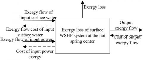
The goal of exergy analysis is to improve the thermal efficiency of the surface WSHP system. However, the optimal setting for the thermal efficiency does not necessarily lead to the optimal economy of different parts of the system. Therefore, the systematic renovation design of the WSHP must be prepared combining thermodynamics with economy. Figure 2 resents the exergy dissipation model of the surface WSHP system, i.e., the thermo-economics model of the system.
Figure 2. Thermo-economics model of the surface WSHP system
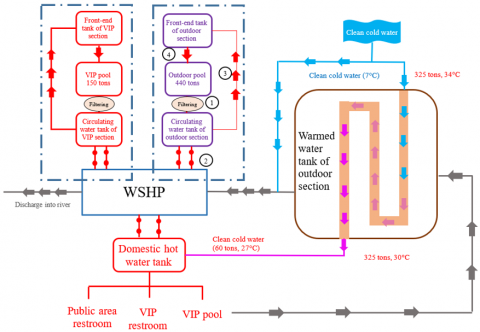
4.2 Optimal design for VIP section
As shown in Figure 3, the low-temperature hot spring water (39℃) in the VIP pool is filtered before flowing into the circulating water tank in the VIP section. From that tank, the low-temperature water is pumped to the WSHP by a circulating water pump. At the WSHP, the water is heated cyclically from 39℃ to 50℃. The work consumed for the heating is the energy loss during the 11℃ of temperature rise at the WSHP. After reaching 50℃, the hot spring water is transmitted by a lift pump to the front-end tank. From that tank, the high-temperature hot spring water flows under gravity to different pools to make up for their heat losses. In this way, the hot spring water in the system is utilized cyclically, without needing additional warmed spring water.
Figure 3. Constant temperature water replenishment of VIP section
Figure 4. Constant temperature water replenishment of outdoor section
4.3 Systematic optimal design of outdoor section and indoor section
As shown in Figure 4, the low-temperature hot spring water (39℃) in the outdoor pool is filtered before flowing into the circulating water tank in the outdoor section. From that tank, the low-temperature water is pumped to the WSHP by a circulating water pump. At the WSHP, the water is heated cyclically from 39℃ to 50℃. The work consumed for the heating is the energy loss during the 11℃ of temperature rise at the WSHP. After reaching 50℃, the hot spring water is transmitted by a lift pump to the front-end tank. From that tank, the high-temperature hot spring water flows under gravity to different pools to make up for their heat losses. In this way, the hot spring water in the system is utilized cyclically, without needing additional warmed spring water. As shown in Figure 5, the constant temperature water replenishment of the indoor section is the same as that in the VIP section and the outdoor section.
Figure 5. Constant temperature water replenishment of indoor section
Figure 6. Primary recycling of waste heat
Figure 7. Secondary recycling of waste heat
4.4 Systematic waste heat recycling
Two approaches were designed to recycle waste heat. The first approach (Figure 6) preheats cold spring water with domestic hot water from 7℃ to 27℃. Then, the spring water is further warmed up to 55℃ by the WSHP. The second approach (Figure 7) extracts heat by the WSHP to keep the hot spring water at a constant temperature. The waste heat is recovered twice. After the two recoveries, all the heat of the hot spring water can be fully utilized. No heat waste will occur.
(1) Primary recycling of waste heat
In winter, all the waste heat of the water from the warmed water tank can be fully utilized. This is understandable because more waste heat can be recycled in winter than any other season. Primary recycling aims to freely preheat the spring water by up to 20℃. The temperature rise does not consume any power. It is equivalent to saving the energy needed to heat 100 tons of spring water from 7℃ to 27℃, which is about 2,333kWh=840kg standard coal. That is, 0.84 tons of standard coal is saved each day.
(2) Secondary recycling of waste heat
After first recycling, there is still lots of heat in the warmed water tank. This part of heat needs to be recycled again. During the secondary recycling, some clean cold water is mixed into the system. Once the water reaches the operating temperature of the WSHP, the pump will extract the heat from the warm water, and use it to maintain the constant temperature of the pools and warm up the domestic hot water.
During secondary recycling, the worst-case recovery of waste heat is calculated in the first step. Since the WSHP of VIP section and outdoor section follows the same principle as that of the indoor section, the secondary recycling is illustrated with VIP and outdoor sections as the example.
The systematic renovation scheme for the WSHP of the hot spring center must minimize the system exergy, or comprehensively adjust the components and operating parameters to minimize the design, renovation, and operating costs of the surface WSHP system. Table 7 compares the thermodynamic optimization and thermo-economic optimization results of the WSHP system. It can be seen that the two optimization strategies differ in direction and objective, and result in different system parameters. Focusing on the best energy efficiency of the system, thermodynamic optimization pursues the minimization of exergy loss of the system. Thermo-economic optimization tries to maximize the economic benefit. To a certain extent, the latter strategy increases the exergy loss of the WSHP, and reduces the energy efficiency ratio of the unit. In the meantime, thermo-economic optimization lowers the design, renovation, and operating costs of the system. Therefore, thermo-economic optimization can effectively control the cost of systematic renovation design for the WSHP of the hot spring center. Based on the operating samples of the WSHP system, the cooling capacity and input power of the WSHP under the cooling state were calculated after the optimization. The optimization coefficients of inlet and outlet water performance are listed in Tables 8 and 9, respectively.
As shown in Table 8, during the cooling state, the input power of the renovated WSHP system gradually decreased with the growing cooling water flow. To effectively reduce system energy consumption, the actual systematic renovation design must fully consider the influence of cooling water flow over WSHP performance.
Table 7. Thermodynamic optimization and thermo-economic optimization results of the WSHP system
|
Parameters |
Suction pressure of compressor |
Discharge pressure of compressor |
Compression ratio |
Compressor power |
Annual electricity bill of compressor |
Evaporation temperature |
Condenser area |
Condensation temperature |
|
Thermodynamic optimization |
1.257 |
2.128 |
3 |
14.96 |
12491 |
8.41 |
4.46 |
34.76 |
|
Thermo-economic optimization |
0.7684 |
2.2145 |
2.5 |
16.75 |
13798 |
4.35 |
4.381 |
31.78 |
|
Parameters |
Surface water supply temperature |
Surface water return temperature |
Chilled water supply temperature |
Chilled water return temperature |
Mass flow of refrigerant |
Surface water flow |
Energy efficiency ratio of pump |
System exergy loss |
|
Thermodynamic optimization |
25 |
28 |
12 |
14 |
0.612 |
4.751 |
6.23 |
12.3715 |
|
Thermo-economic optimization |
23 |
27 |
5 |
12 |
0.3756 |
13.26 |
5.71 |
13.7541 |
Table 8. Optimization coefficients of inlet water performance under the cooling state
|
Inlet water temperature of evaporators |
Inlet water temperature of condensers |
|||||||||
|
12 |
16 |
19 |
23 |
24 |
||||||
|
Cooling capacity |
Input power |
Cooling capacity |
Input power |
Cooling capacity |
Input power |
Cooling capacity |
Input power |
Cooling capacity |
Input power |
|
|
12 |
0.98 |
0.85 |
0.97 |
0.95 |
0.99 |
0.97 |
0.88 |
1.08 |
0.94 |
1.09 |
|
13 |
1.07 |
0.92 |
1.03 |
0.98 |
1.03 |
1.09 |
0.97 |
1.09 |
0.93 |
1.2 |
|
16 |
1.14 |
0.94 |
1.2 |
1.10 |
1.12 |
1.08 |
1.25 |
1.2 |
0.98 |
1.16 |
|
17 |
1.3 |
0.95 |
1.15 |
1.15 |
1.17 |
1.09 |
1.23 |
1.12 |
0.85 |
1.23 |
|
19 |
1.34 |
0.96 |
1.23 |
1.23 |
1.25 |
1.07 |
1.34 |
1.15 |
1.17 |
1.14 |
|
21 |
1.42 |
0.98 |
1.27 |
1.27 |
1.26 |
1.12 |
014 |
1.14 |
1.23 |
1.3 |
Table 9. Optimization coefficients of outlet water performance under the cooling state
|
Outlet water temperature of evaporators |
Outlet water temperature of condensers |
|||||||||
|
23 |
24 |
30 |
33 |
37 |
||||||
|
Cooling capacity |
Input power |
Cooling capacity |
Input power |
Cooling capacity |
Input power |
Cooling capacity |
Input power |
Cooling capacity |
Input power |
|
|
8 |
0.96 |
0.85 |
0.95 |
0.97 |
0.93 |
0.88 |
0.85 |
1.05 |
0.92 |
1.08 |
|
6 |
1.04 |
0.92 |
1.03 |
0.98 |
1 |
0.97 |
0.97 |
1.07 |
0.95 |
1.1 |
|
10 |
1.12 |
0.96 |
1.2 |
0.96 |
1.05 |
1.05 |
1.06 |
1.09 |
1.02 |
1.15 |
|
12 |
1.3 |
0.94 |
1.15 |
1.04 |
1.09 |
1.07 |
1.12 |
1.2 |
1.03 |
1.17 |
|
14 |
1.33 |
0.99 |
1.23 |
1.03 |
1.06 |
1.08 |
1.17 |
1.23 |
1.12 |
1.2 |
|
18 |
1.38 |
1.02 |
1.27 |
1.05 |
1.07 |
1.05 |
1.08 |
1.25 |
1.14 |
1.23 |
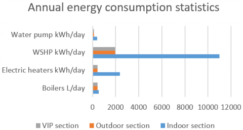
Figure 8. Total annual energy consumption of the WSHP system
In the light of the above precautions, the energy consumption of the WSHP system optimized by our scheme was calculated for each season. Figure 8 shows the total annual energy consumption of the WSHP system at the hot spring center. Figure 9 shows the proportion of different seasons in total annual energy consumption. It can be seen that spring and autumn accounted for 72% of the total annual energy consumption, summer accounted for 10%, and winter accounted for 18%.
Figure 9. Proportion of different seasons in total annual energy consumption
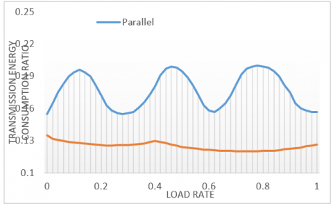
The total energy consumption, thermal performance index, and transmission energy consumption ratio of the WSHP system (Figures 10-12) were calculated under the two waste heat recycling schemes, respectively, and compared with the results under constant flow operation. The results show that the two schemes brought a lower total energy consumption than the constant flow operation state. When the load rate fluctuated in [1/4, 1], the total energy consumption under secondary recycling was 6.85% higher than that under primary recycling; the thermal performance index under secondary recycling was 38% greater than that under primary recycling; the transmission energy consumption ratio under secondary recycling was 15.4% lower than that under primary recycling.
Figure 10. Total energy consumptions under the two waste heat recycling schemes
Figure 11. Thermal performance indices under the two waste heat recycling schemes
Figure 12. Transmission energy consumption ratios under the two waste heat recycling schemes
This paper carries out a systematic renovation design of the surface WSHP in a hot spring center in the national forest park of northern Guilin, Guangxi. The main steps include the design of hot spring system, air-conditioning system, and hot water system, as well as the exergy analysis of WSHP system. Among them, the design of hot spring system covers the regulation of raw water, cold water, and warmed water; the constant temperature control of hot spring pools; the waste heat utilization of warmed water from the pools. The following conclusions can be drawn from the experimental results:
(1) This paper establishes a WSHP operating system with heat pump technology. The proposed system can extract as much natural heat as possible, and maximize the scale of hot spring pools, while keeping a constant temperature. Under the proposed system, the hot spring can be used flexibly by visitors, and different sections can be opened/closed depending on the visitor scale, thereby saving energy consumption.
(2) It is recommended to use an automation control system, and monitor the filtering system. The back flush devices need to be turned on at preset time. Moreover, unattended operation should be realized to automatically monitor the water temperature, quality, and volume in each section.
(3) The height of the machine room should be lower than that of the warmed water tank, so that the warned water can flow under gravity to the WSHP, eliminating the need for additional water pumps. Furthermore, the heat preservation water tanks should be placed at windless positions to reduce heat dissipation and facilitate insulation.
[1] Knuutinen, J., Böök, H., Ruuskanen, V., Ruuskanen, A. K., Immonen, P., Ahola, J. (2021). Ground source heat pump control methods for solar photovoltaic-assisted domestic hot water heating. Renewable Energy, 177: 732-742. https://doi.org/10.1016/j.renene.2021.05.139
[2] Schön, B. (2017). Developing performance of waste water source heat pump systems by heat transport investigation. In 2017 6th International Youth Conference on Energy (IYCE), pp. 1-12. https://doi.org/10.1109/IYCE.2017.8003690
[3] Jeong, Y.D., Yu, M.G., Nam, Y. (2017). Feasibility study of a heating, cooling and domestic hot water system combining a photovoltaic-thermal system and a ground source heat pump. Energies, 10(8): 1243. https://doi.org/10.3390/en10081243
[4] Bouheret, S., Bernier, M. (2018). Modelling of a water-to-air variable capacity ground-source heat pump. Journal of Building Performance Simulation, 11(3): 283-293. https://doi.org/10.1080/19401493.2017.1332686
[5] Eslami-Nejad, P., Badache, M., Bastani, A., Aidoun, Z. (2018). Detailed theoretical characterization of a transcritical CO2 direct expansion ground source heat pump water heater. Energies, 11(2): 387. https://doi.org/10.3390/en11020387
[6] Deutz, K.R., Charles, G.L., Cauret, O., Rullière, R., Haberschill, P. (2018). Detailed and dynamic variable speed air source heat pump water heater model: Combining a zonal tank model approach with a grey box heat pump model. International Journal of Refrigeration, 92: 55-69. https://doi.org/10.1016/j.ijrefrig.2018.05.022
[7] Zou, S., Xie, X. (2017). Simplified model for coefficient of performance calculation of surface water source heat pump. Applied Thermal Engineering, 112: 201-207. https://doi.org/10.1016/j.applthermaleng.2016.10.081
[8] Tangwe, S.L., Simon, M., Meyer, E.L. (2017). Prediction of coefficient of performance and simulation design of an air-source heat pump water heater. Journal of Engineering, Design and Technology, 15(3): 378-394. https://doi.org/10.1108/JEDT-06-2016-0042
[9] Markovic, R., Lorz, C., Frisch, J., van Treeck, C. (2017). Application of support vector machine for predicting the performance of air-source domestic hot water heat pump systems. In Building Simulation Proceedings of the 15th IBPSA Conference, San Francisco, CA, USA, 3: 1185-1194.
[10] Aprile, M., Scoccia, R., Toppi, T., Motta, M. (2017). Gray-box entropy-based model of a water-source NH3-H2O gas-driven absorption heat pump. Appl. Therm. Eng, 118: 214-223.
[11] Vivian, J., Prataviera, E., Cunsolo, F., Pau, M. (2020). Demand Side Management of a pool of air source heat pumps for space heating and domestic hot water production in a residential district. Energy Conversion and Management, 225: 113457. https://doi.org/10.1016/j.enconman.2020.113457
[12] Mouzeviris, G.A., Papakostas, K.T. (2021). Comparative analysis of air-to-water and ground source heat pumps performances. International Journal of Sustainable Energy, 40(1): 69-84. https://doi.org/10.1080/14786451.2020.1794864
[13] Cardemil, J.M., Schneider, W., Behzad, M., Starke, A. R. (2021). Thermal analysis of a water source heat pump for space heating using an outdoor pool as a heat source. Journal of Building Engineering, 33: 101581. https://doi.org/10.1016/j.jobe.2020.101581
[14] Tangwe, S., Kusakana, K. (2021). The economic and environmental impact of replacing geyser with air source heat pump water heater. In 2021 Southern African Universities Power Engineering Conference/Robotics and Mechatronics/Pattern Recognition Association of South Africa (SAUPEC/RobMech/PRASA), pp. 1-6. https://doi.org/10.1109/SAUPEC/RobMech/PRASA52254.2021.9377225
[15] Long, J., Xia, K., Zhong, H., Lu, H., Yongga, A. (2021). Study on energy-saving operation of a combined heating system of solar hot water and air source heat pump. Energy Conversion and Management, 229: 113624. https://doi.org/10.1016/j.enconman.2020.113624
[16] Manyi-Loh, C.E., Sikhonza, M., Tangwe, S. (2021). Linear regression analysis and techno-economic viability of an air source heat pump water heater in a residence at a university campus. Energies, 14(8): 2280. https://doi.org/10.3390/en14082280
[17] Duarte, W.M., Paulino, T.F., Tavares, S.G., Maia, A.A., Machado, L. (2021). Feasibility of solar-geothermal hybrid source heat pump for producing domestic hot water in hot climates. International Journal of Refrigeration, 124: 184-196. https://doi.org/10.1016/j.ijrefrig.2020.12.022
[18] Sikhonza, M., Tangwe, S., Simon, M. (2020). Energy management opportunities exploration in a residential air source heat pump water heater. In 2020 International SAUPEC/RobMech/PRASA Conference, pp. 1-6. https://doi.org/10.1109/SAUPEC/RobMech/PRASA48453.2020.9041120
[19] Kazi, J.R., Agrawal, N. (2020). Experimental investigation of dehumidifier hybrid air conditioner integrated zeotropic refrigerant blend R-407C air source water heat pump. In Renewable Energy and Climate Change, 161: 175-183. https://doi.org/10.1007/978-981-32-9578-0_16
[20] Deymi-Dashtebayaz, M., Namanlo, S.V., Arabkoohsar, A. (2019). Simultaneous use of air-side and water-side economizers with the air source heat pump in a data center for cooling and heating production. Applied Thermal Engineering, 161: 114133. https://doi.org/10.1016/j.applthermaleng.2019.114133
[21] Sikhonza, M., Tangwe, S., Simon, M. (2018). Statistical analysis of split type air source heat pump water heaters. In 2018 International Conference on the Domestic Use of Energy (DUE), pp. 1-8. https://doi.org/10.23919/DUE.2018.8384388
[22] Masip, X., Navarro-Peris, E., Corberán, J.M. (2020). Influence of the thermal energy storage strategy on the performance of a booster heat pump for domestic hot water production system based on the use of low temperature heat source. Energies, 13(24): 6576. https://doi.org/10.3390/en13246576
[23] Barrella, R., Priego, I., Linares, J.I., Arenas, E., Romero, J.C., Centeno, E. (2020). Feasibility study of a centralised electrically driven air source heat pump water heater to face energy poverty in block dwellings in Madrid (Spain). Energies, 13(11): 2723. https://doi.org/10.3390/en13112723
[24] Ahmed, K., Fadejev, J., Kurnitski, J. (2019). Modeling an alternate operational ground source heat pump for combined space heating and domestic hot water power sizing. Energies, 12(11): 2120. https://doi.org/10.3390/en12112120
[25] Choyu, W., Toshiyuki, N., Motoki, Y., Tomoyuki, Y., Atsuki, H., Tadayoshi, A., Tomita, Shuto, T. (2019). Experimental study on a water and air source high-temperature heat pump using a low GWP refrigerant. Refrigeration Science and Technology, pp. 4934-4941.
[26] Ryoichi, N., Tetsuaki, T., Shuhei, I., Marumo, Yuki, M. (2019). Performance of ground source heat pump that uses direct expansion method for supplying hot water. Refrigeration Science and Technology, pp. 4424-4430.
[27] Ran, S., Li, X., Xu, W., Wang, B. (2020). A solar-air hybrid source heat pump for space heating and domestic hot water. Solar Energy, 199: 347-359. https://doi.org/10.1016/j.solener.2020.02.038
[28] Ozturk, M.M., Doğan, B., Erbay, L.B. (2020). Performance assessment of an air source heat pump water heater from exergy aspect. Sustainable Energy Technologies and Assessments, 42: 100809. https://doi.org/10.1016/j.seta.2020.100809